Over the past few days I spent some time organizing the next few parts of the Empennage such as organizing the Vertical Stabilizer parts and what I needed to finish for the Rudder.
Fitting the Anti-collision light
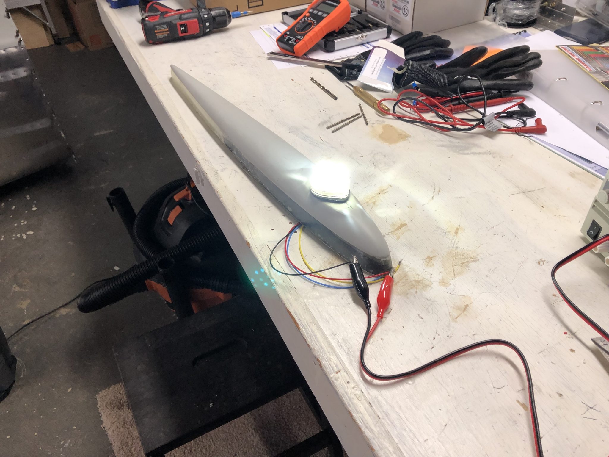
I got the Aveo Posistrobe MiniMax anti-collision light to mount onto the rudder tip and started working on fitting it on.
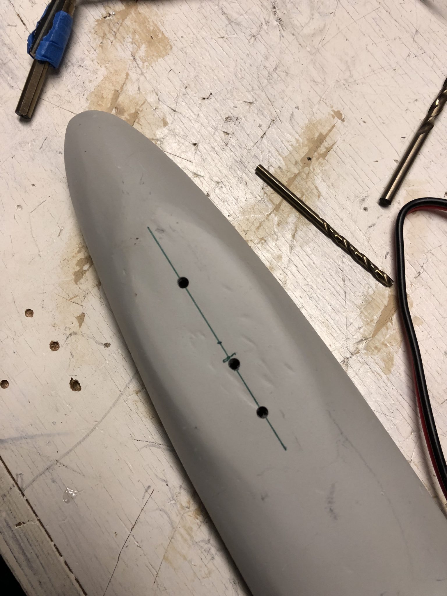

Light temporarily on top and shining bright like a diamond.
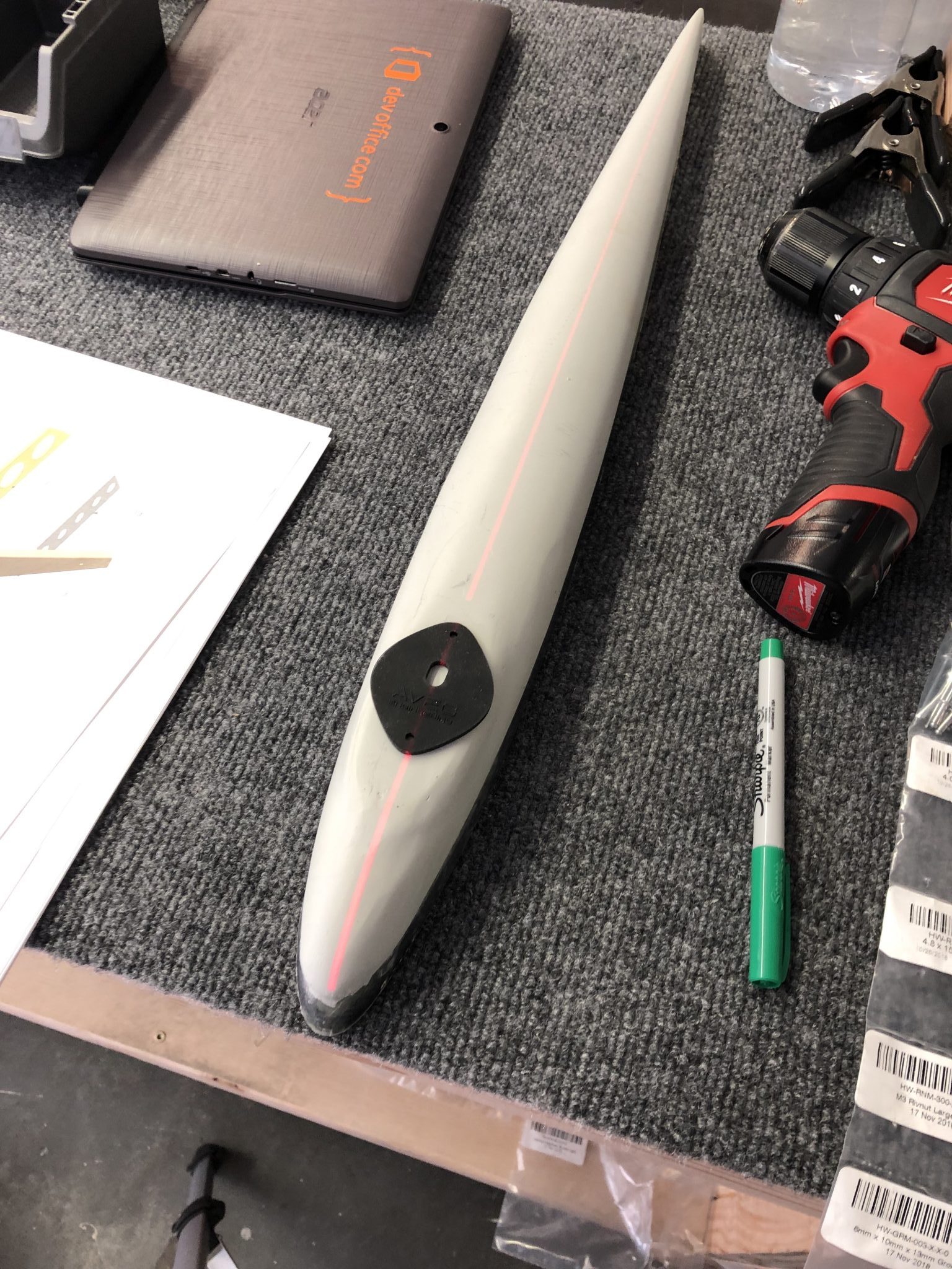
Mounting plate
The first iteration of the Empennage assembly instructions called out for a mounting plate to go inside the fiberglass tip to add structural reinforcement for the rivnuts, but the latest version of the instructions is missing it, so I sent a question to the factory why.
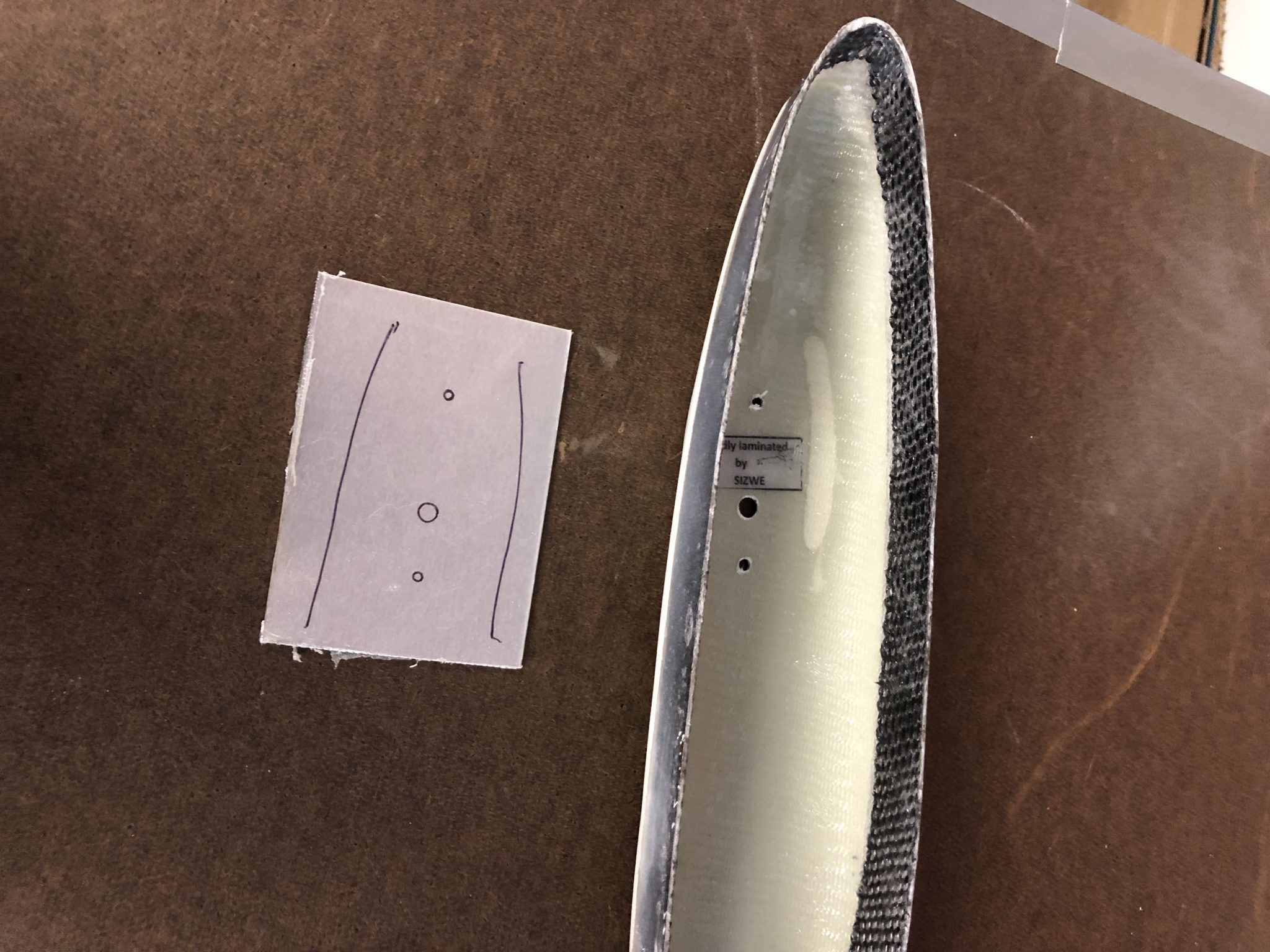
In the meantime, since I assume that it’s still a good idea since both the Sling 4 instructions as well as the first version of the instruction call for it, I decided to fabricate my own.
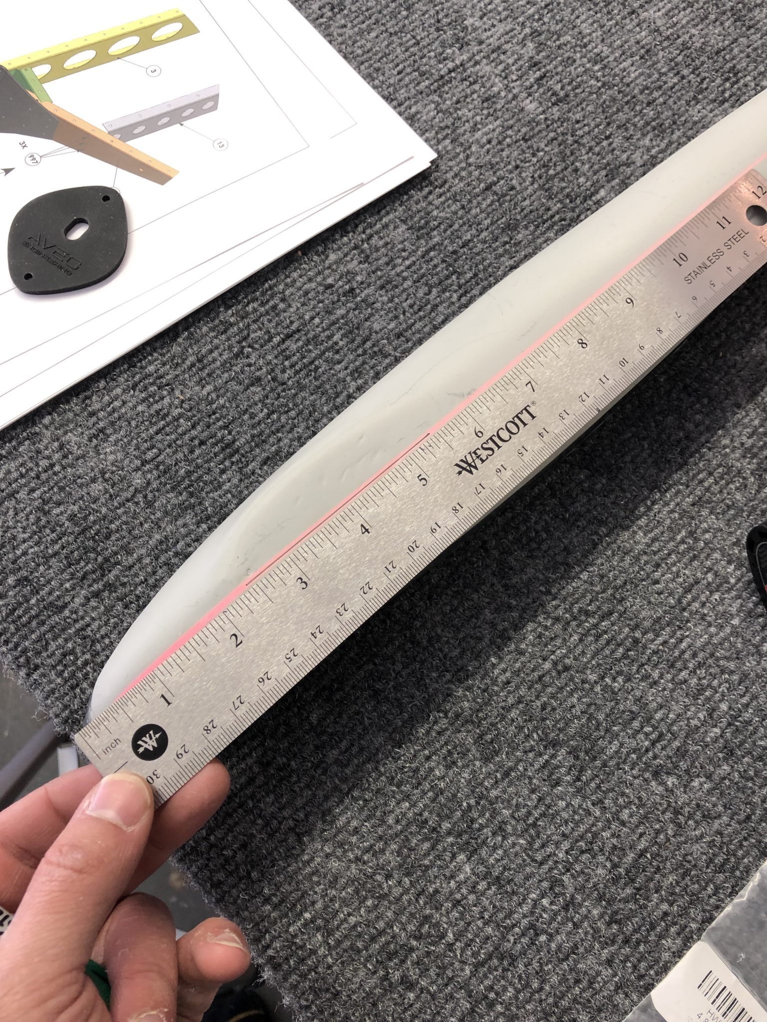
I started tracing out the rough dimensions of the area and then measured it down to how it would fit. Then I made a first version out of cardboard to see if the dimensions I estimated would work.
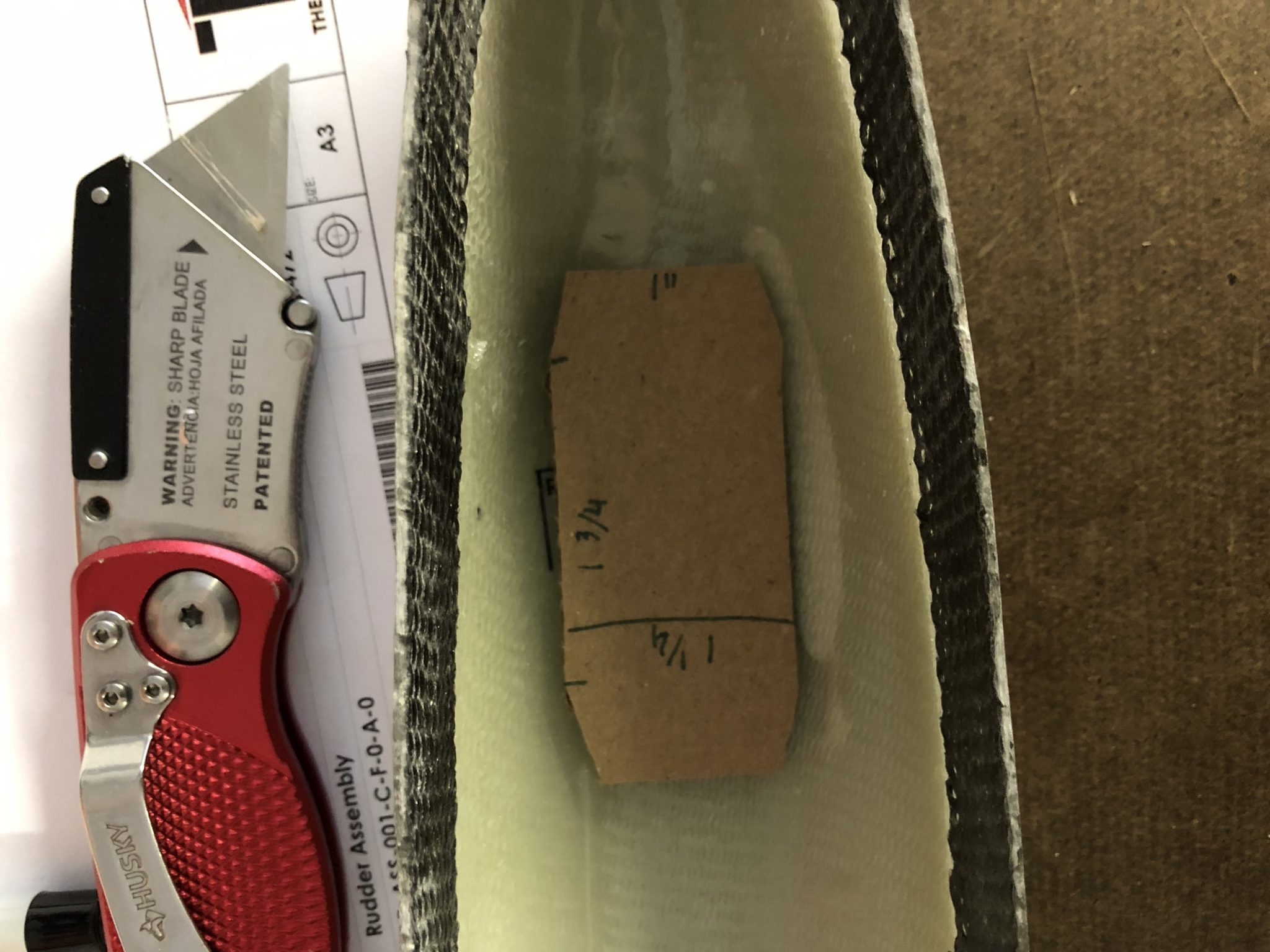
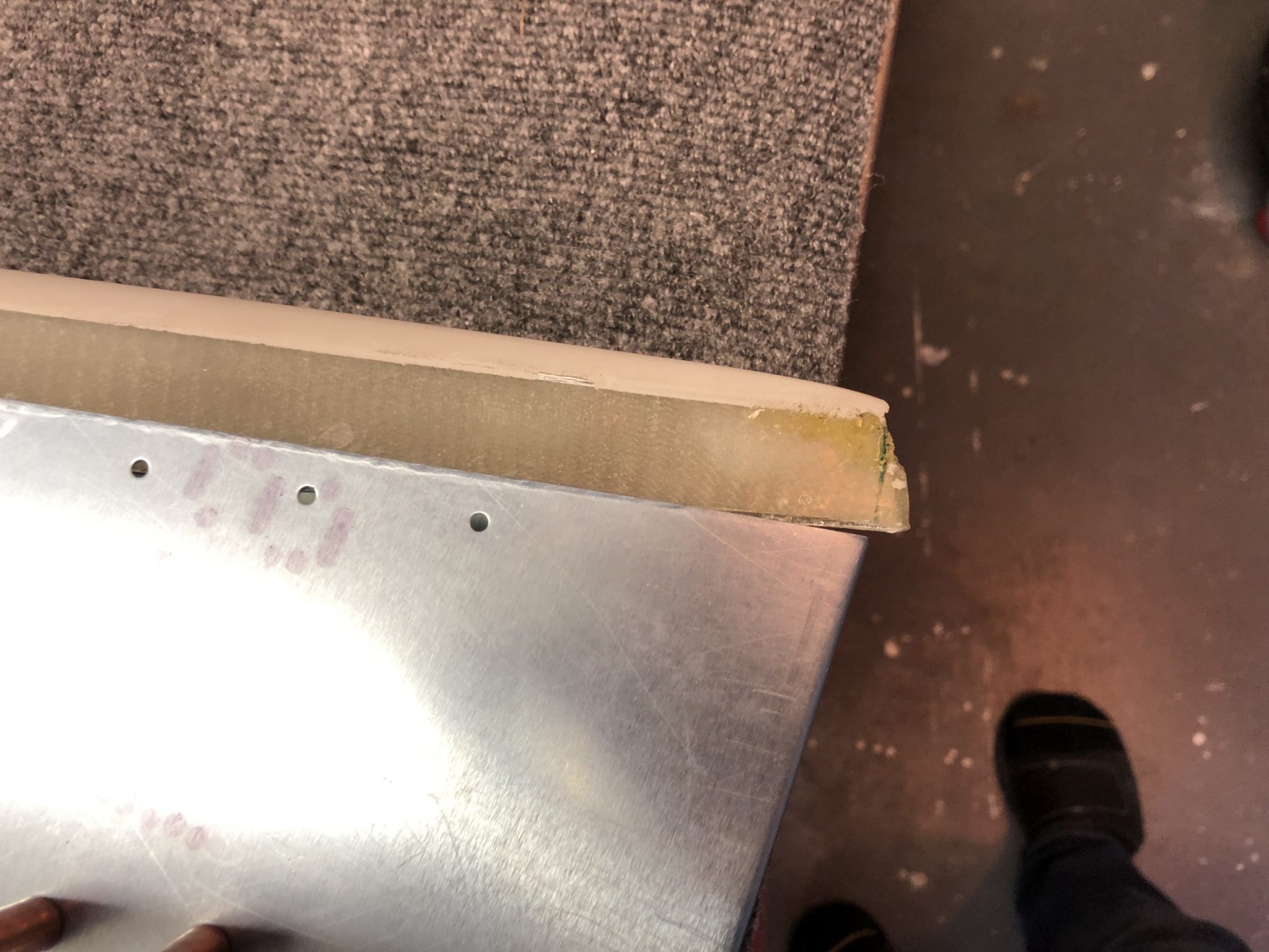
Looked good, so then I copied my cutout onto the sheet metal and went to work cutting it out. I used a OLFA Scoring knive to score the cut, based on a tip from HomebuiltHELP. Since my metal was pretty thick I only scored it with that and then used metal snips to cut it, but for thinner metal you can actually make the whole cut using the scoring knive to make great straight cuts.
After that, I deburred all the edges and the holes and then checked the final fit in the rudder tip.
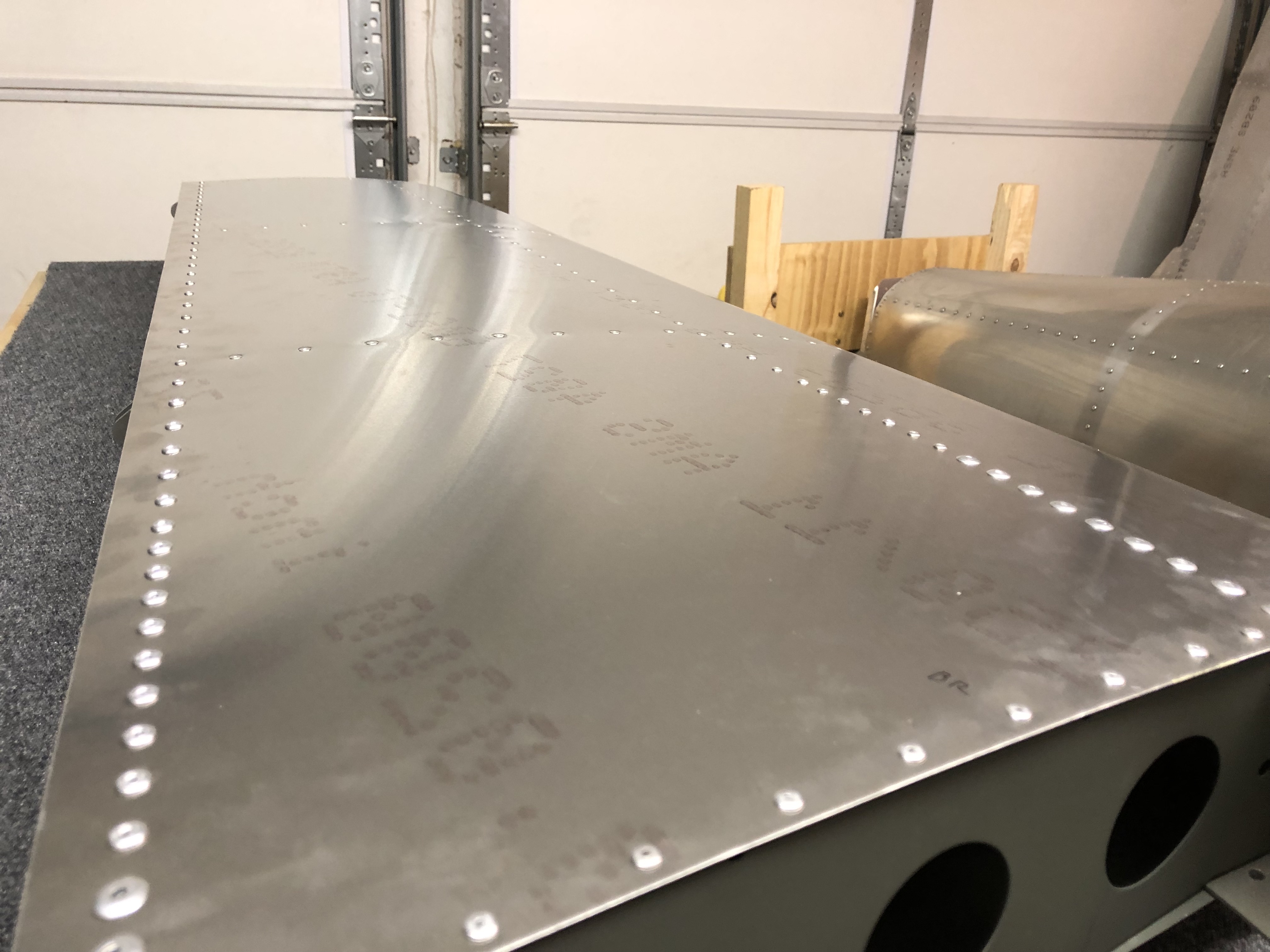
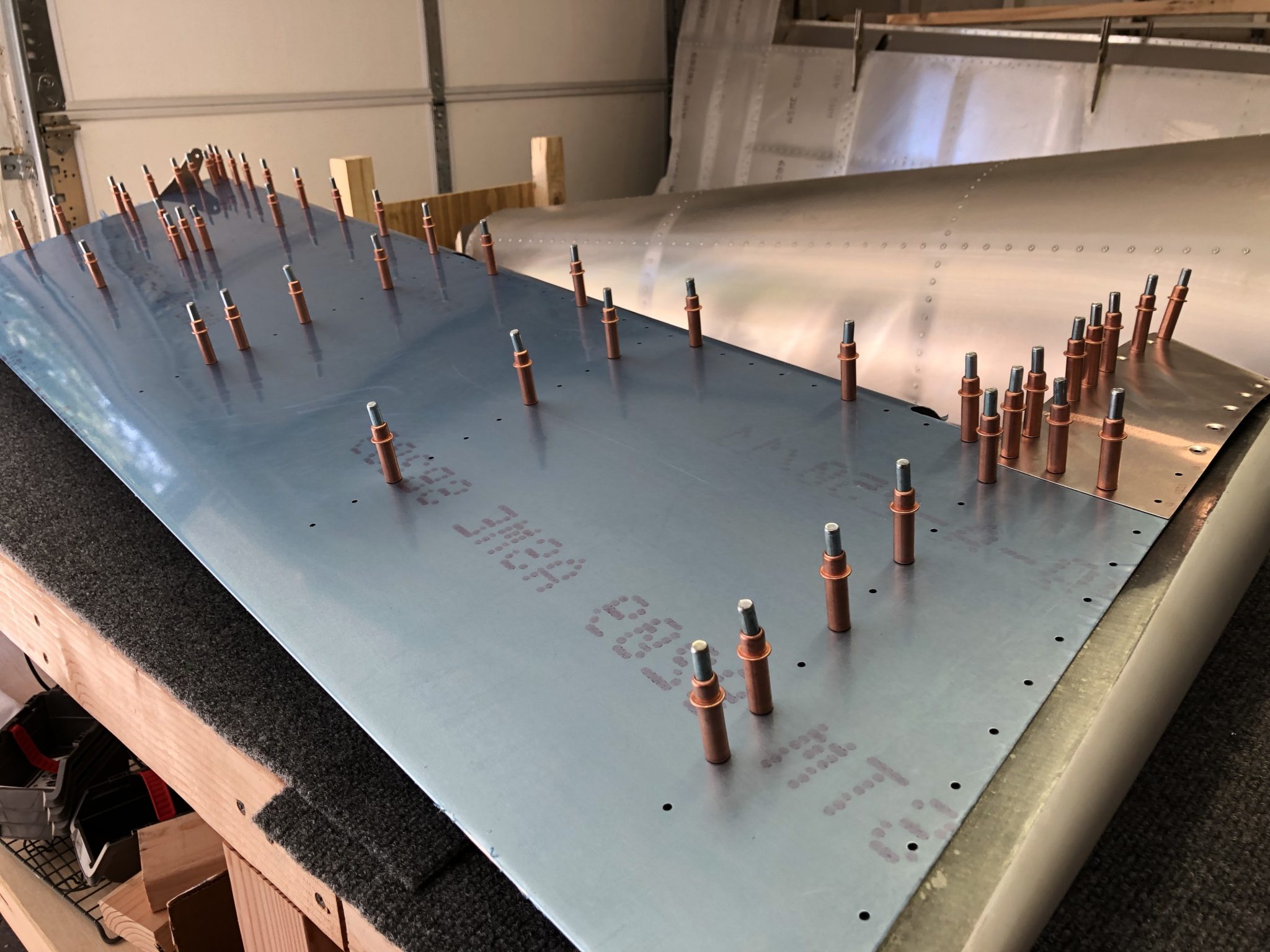
Fitting the skin
I also test fitted the skin onto the rudder and checked how the tip will fit in. The skin came on fairly easily, but I will have to trim a little bit of the fiberglass tip so it will fit in.
I still had to prime the inside of the skin, so now that I know it all fits together fine, I will rivet the skin on and then work on the final trimming for the rudder tip so it fits in and then I will need to match drill the holes into the fiberglass tip and countersink the front holes.