With most of the preparations out of the way and half of the skins riveted, I took one more session to finishing the Elevator.
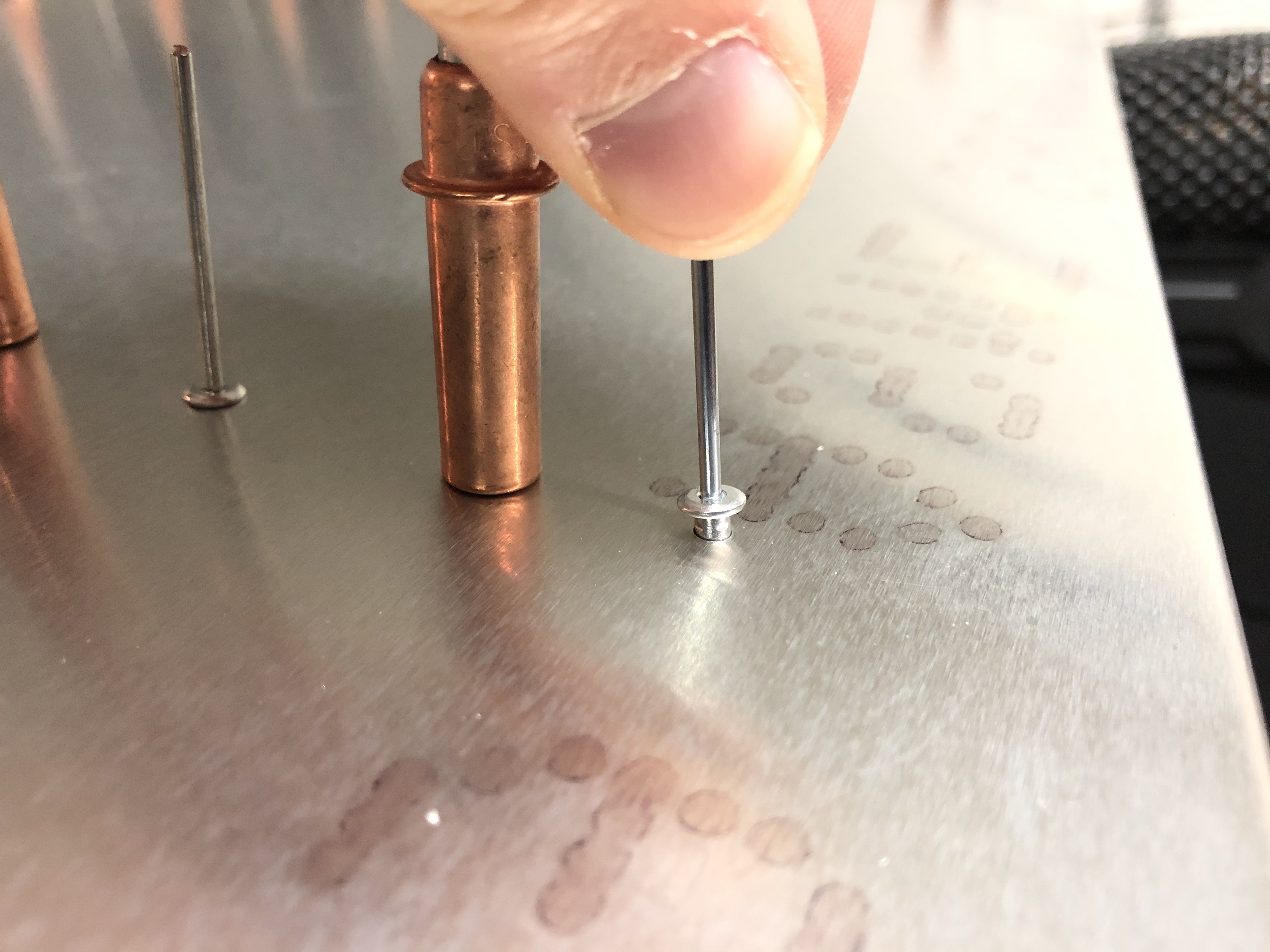
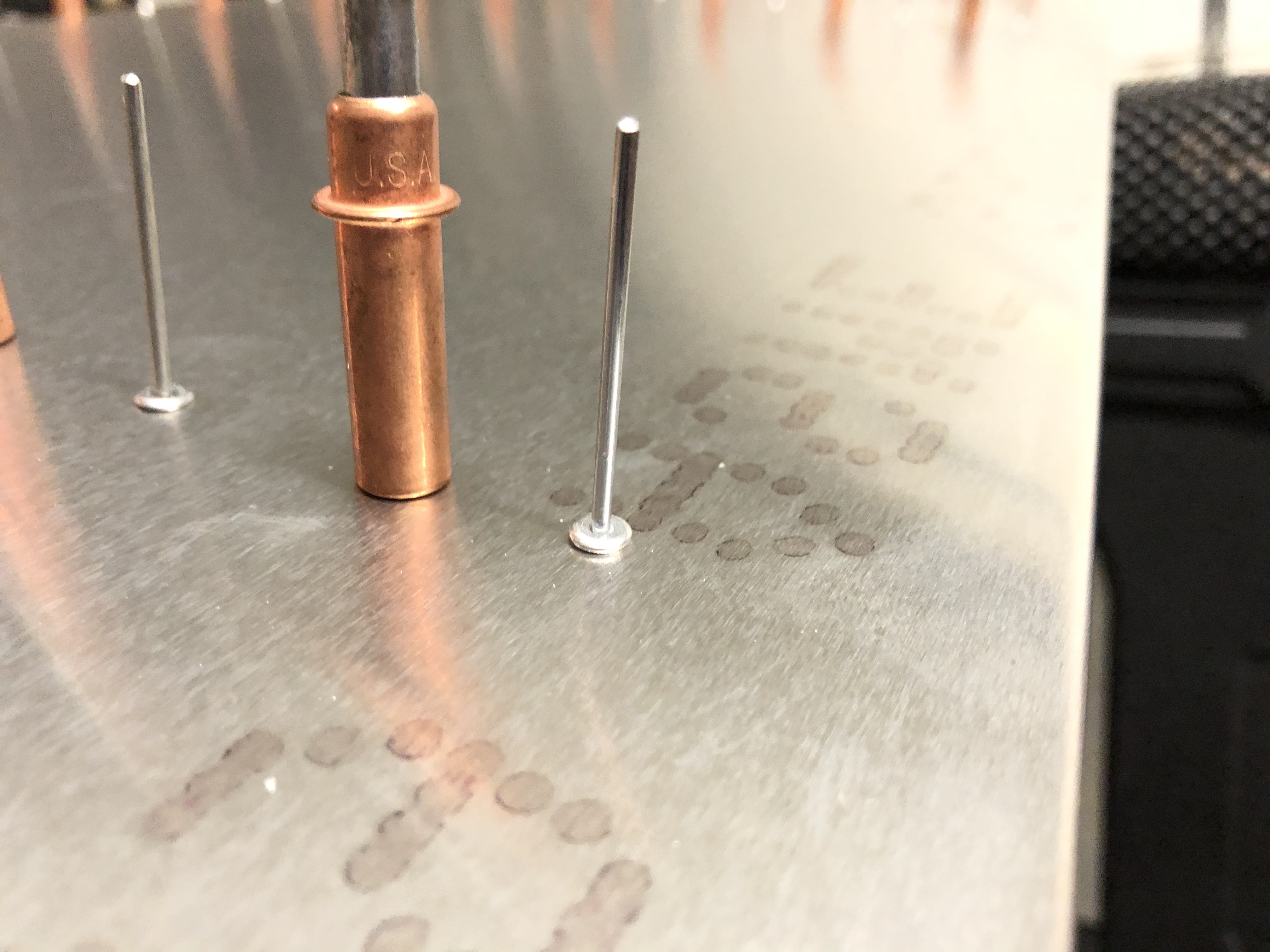
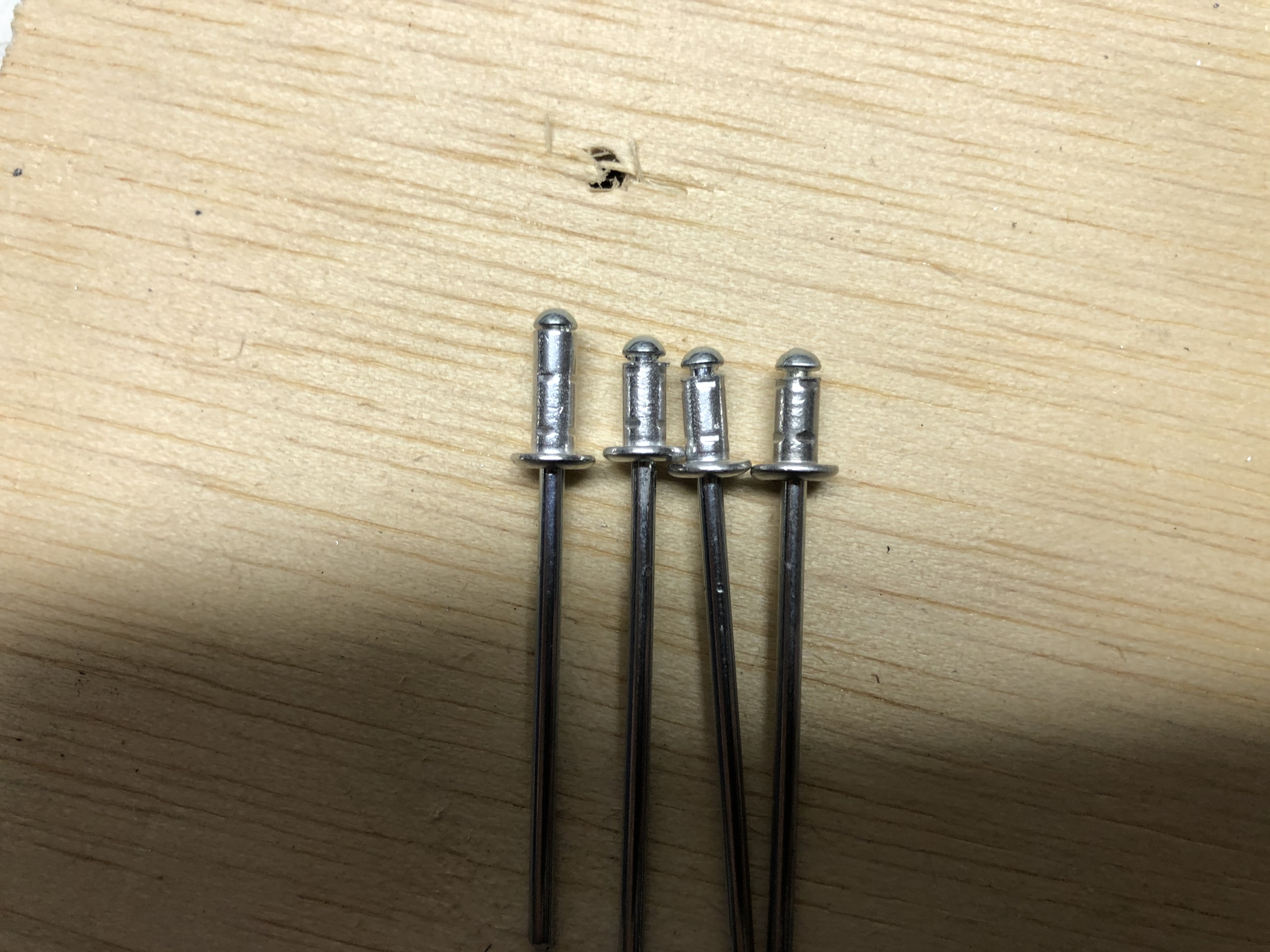
There was only one extra part I had to do for 3 of the rivets that were on the bottom edge. In order for them to fit correctly, I had to shorten the rivets so they wouldn’t protrude out.
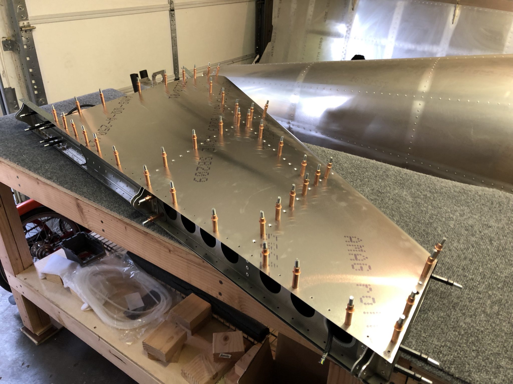
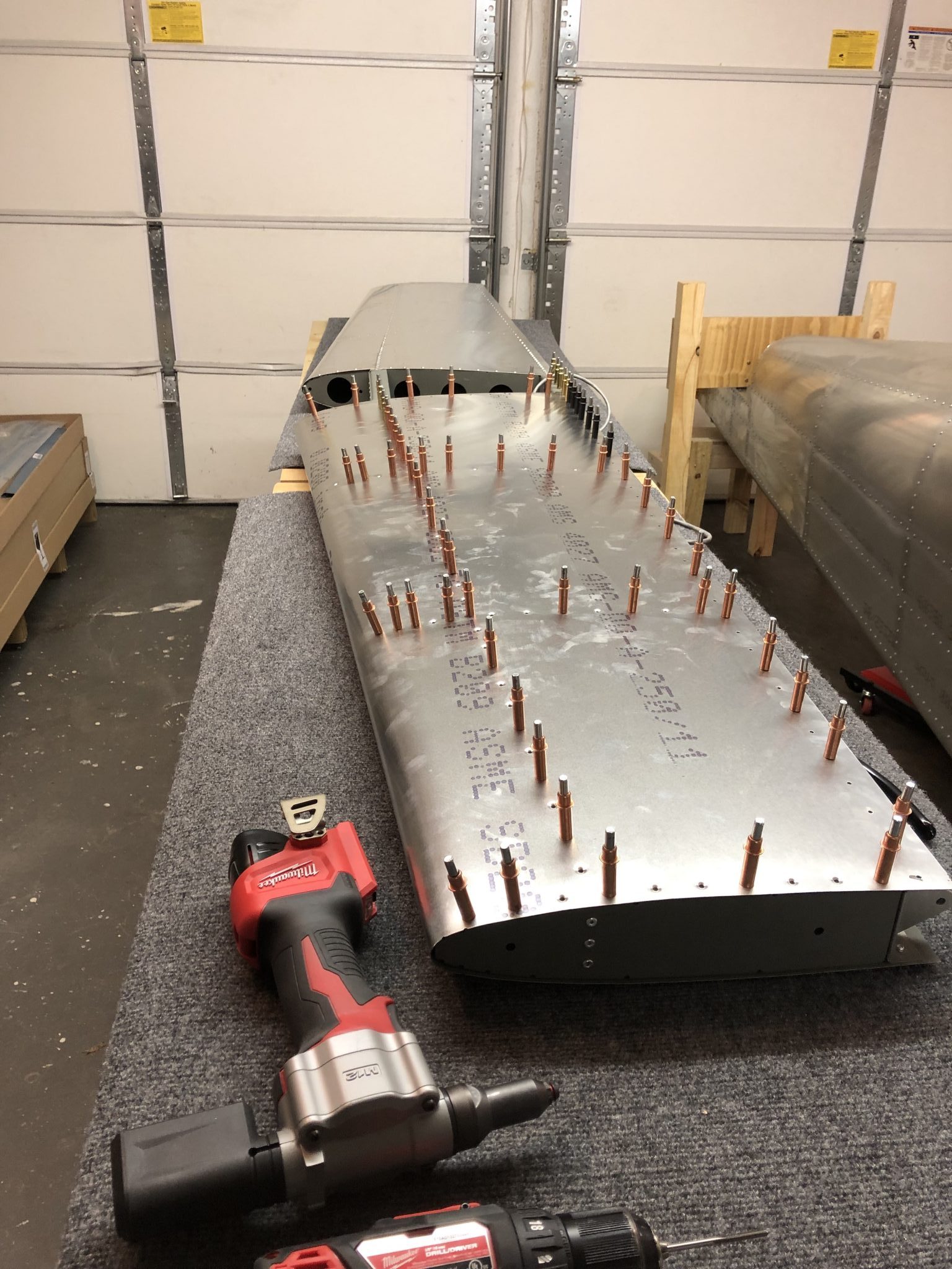
Aside from that, I just went to town and pulled the rest of the few hundred rivets.
The last part on the riveting side was the front lip.
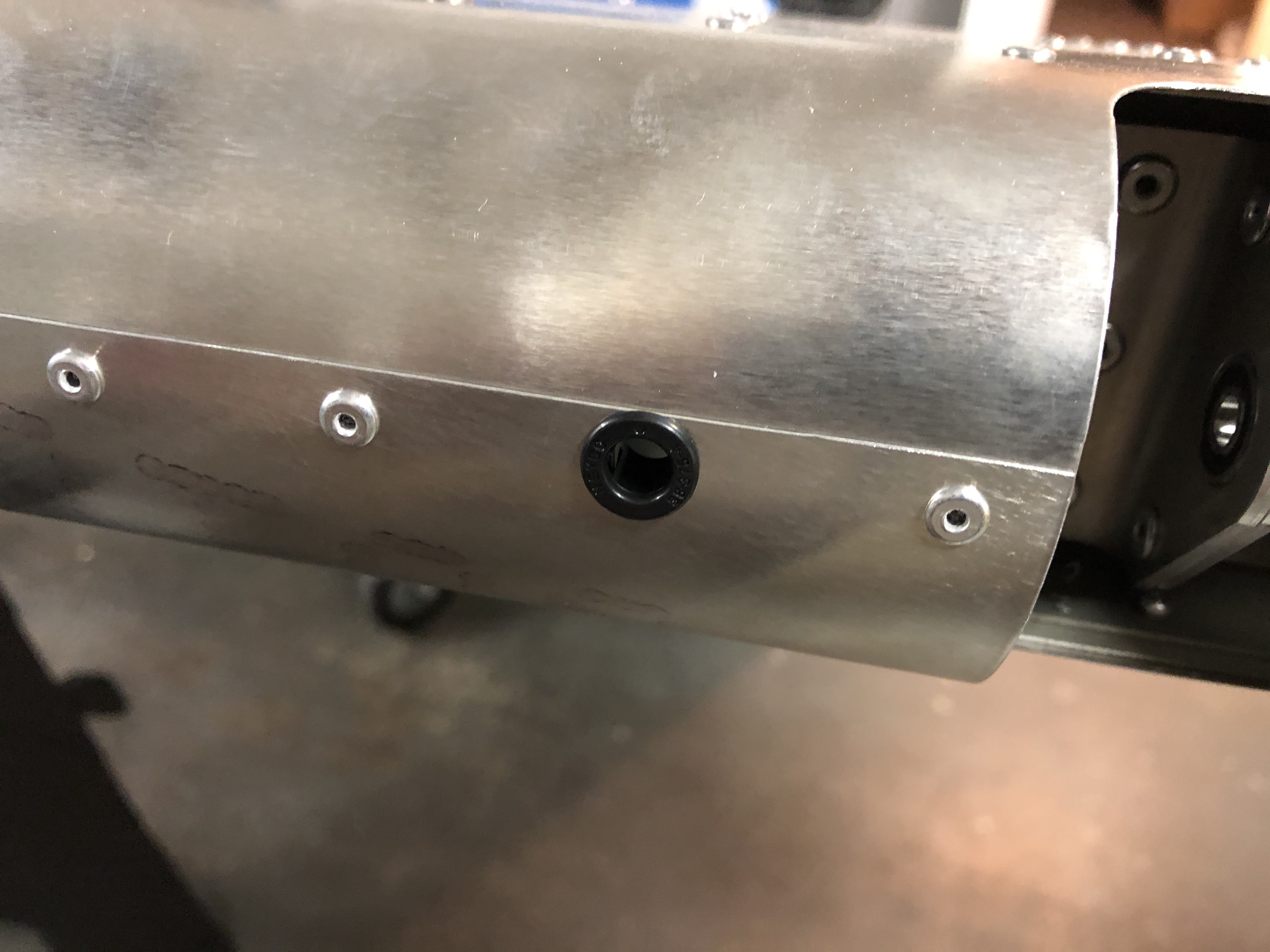
One of the holes on the lip has to be enlarged to fit a grommet for the wiring for the Elevator Trim Tab. I enlarged the hole using my step drill bit and then installed a snap bushing.
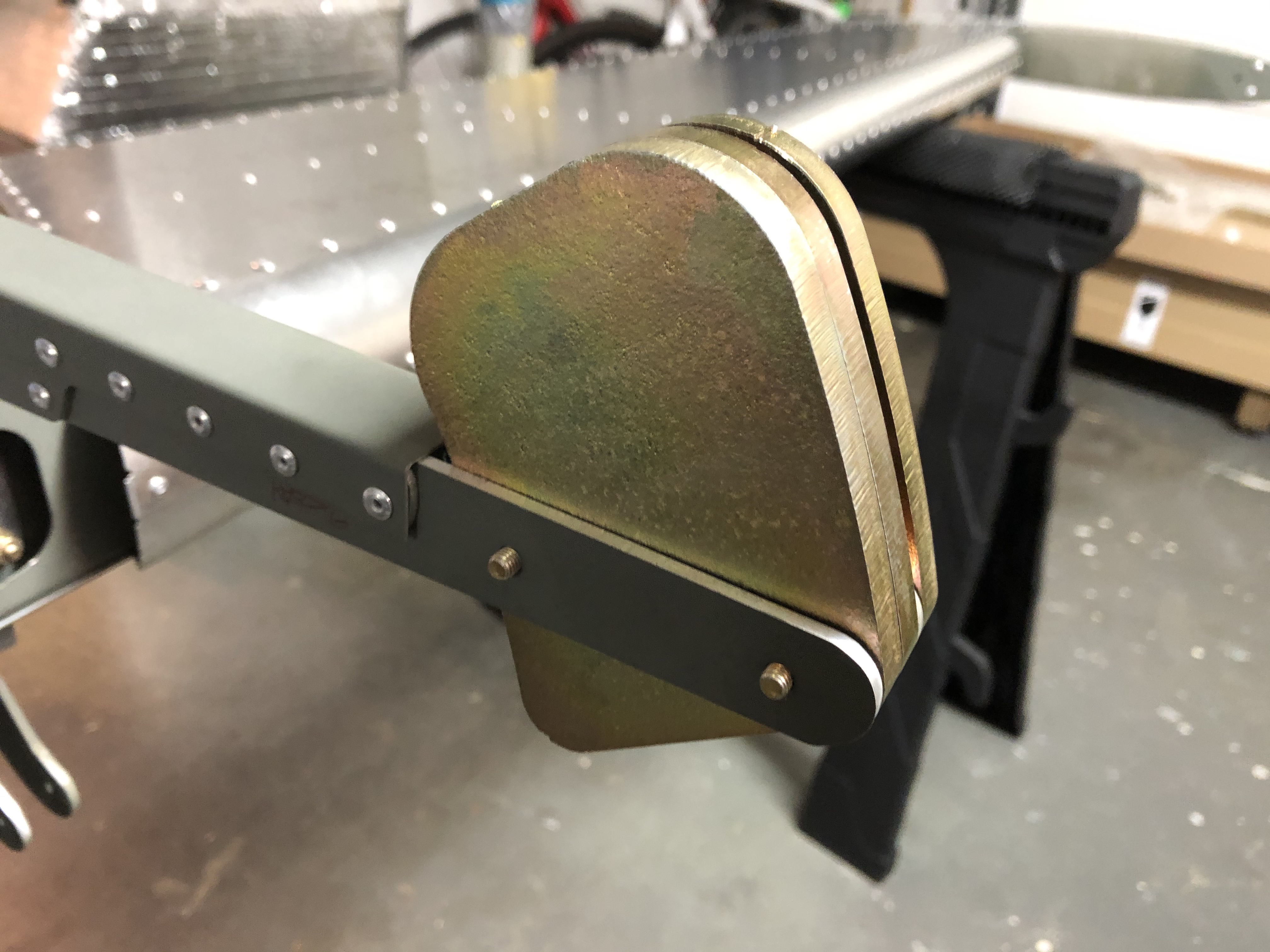
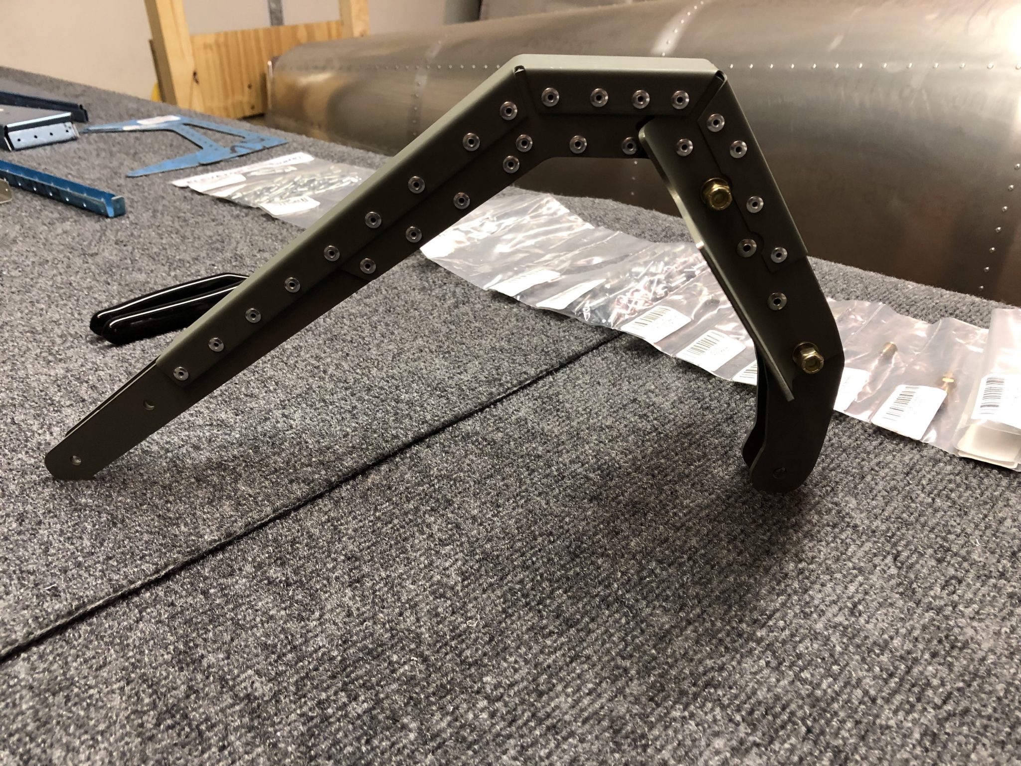
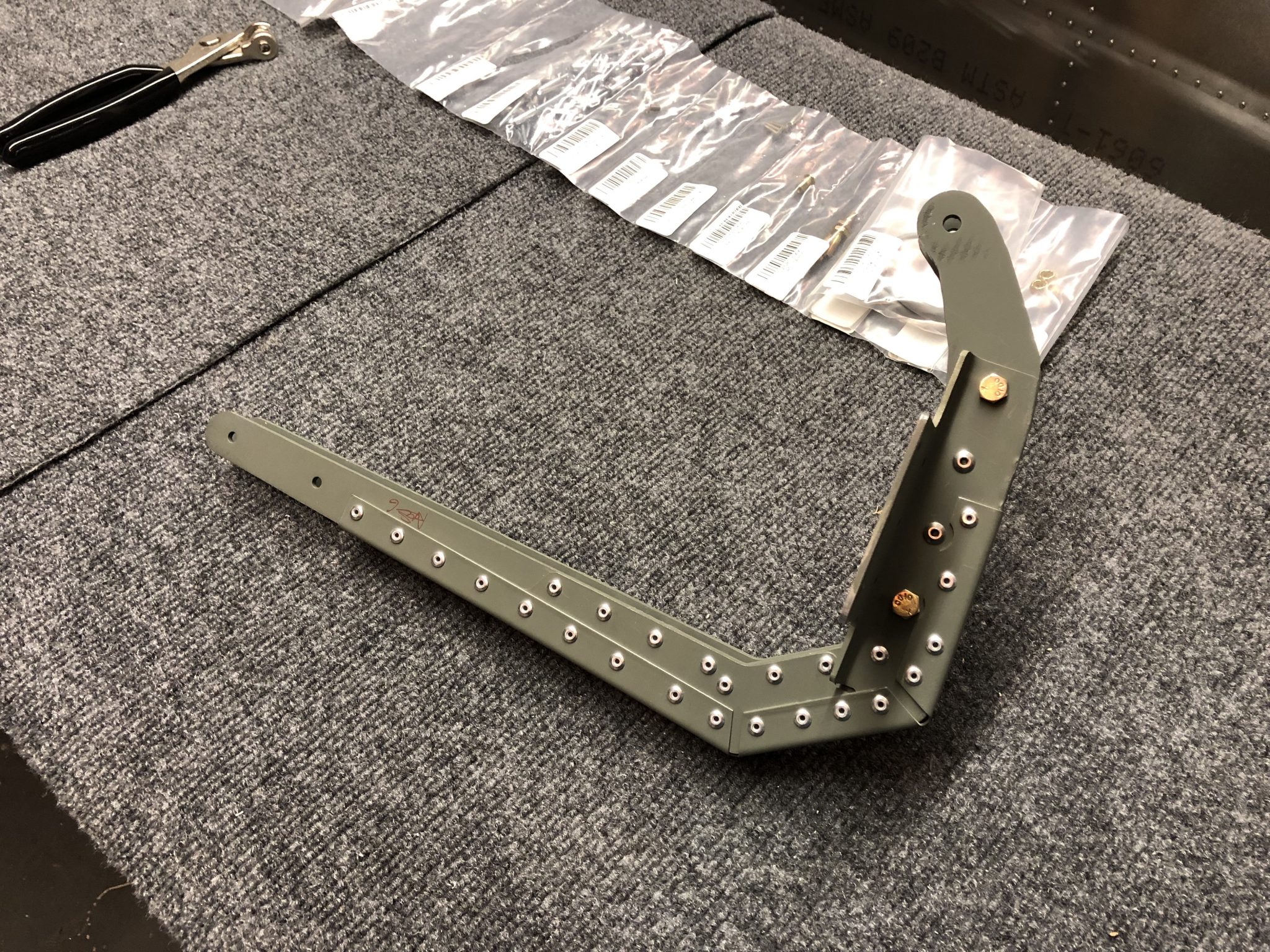
The last part was to install the center balance counterweight. I did some test fitting with this, but the AN3-13A bolts that one of the versions of the manual that I have mentioned are too short, so I’ll check with the factory on the proper length.
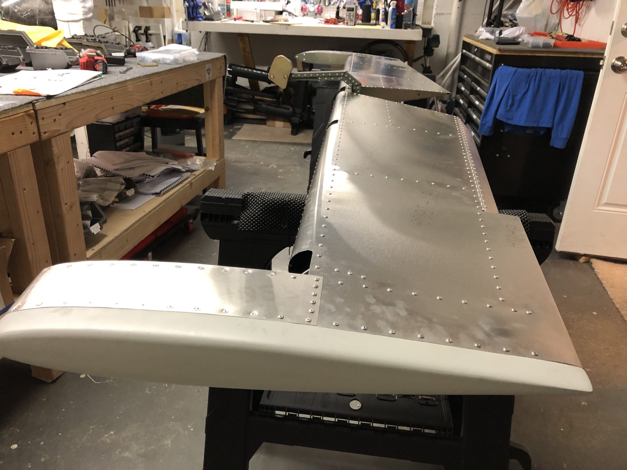
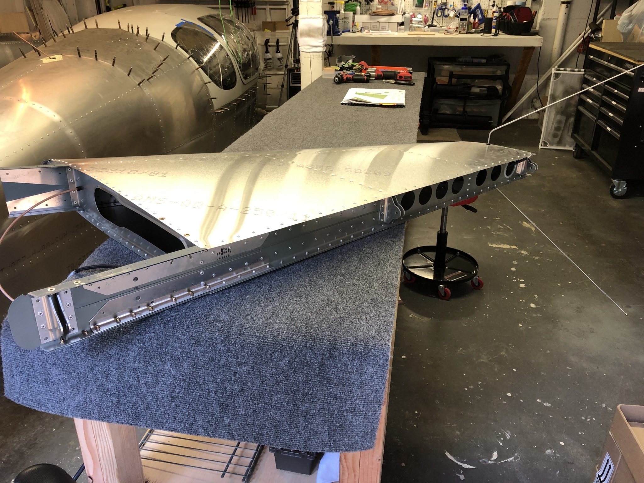
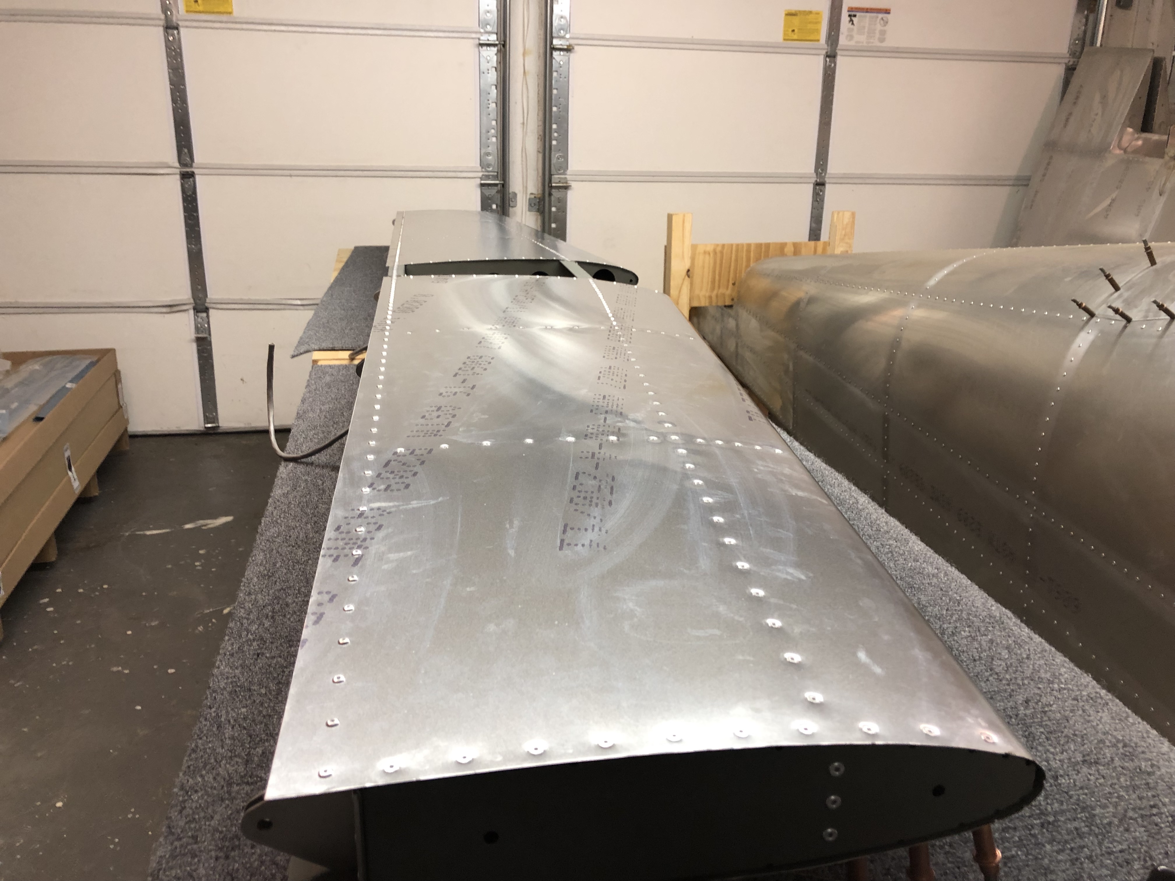
With that being said, the general assembly of the Elevator is completed:
Timelapse of the complete construction of the Elevator
With the Elevator construction completed, I’ve also finished my video timelapse of the process:
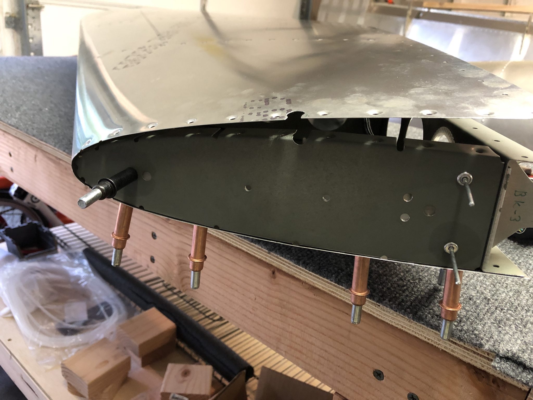
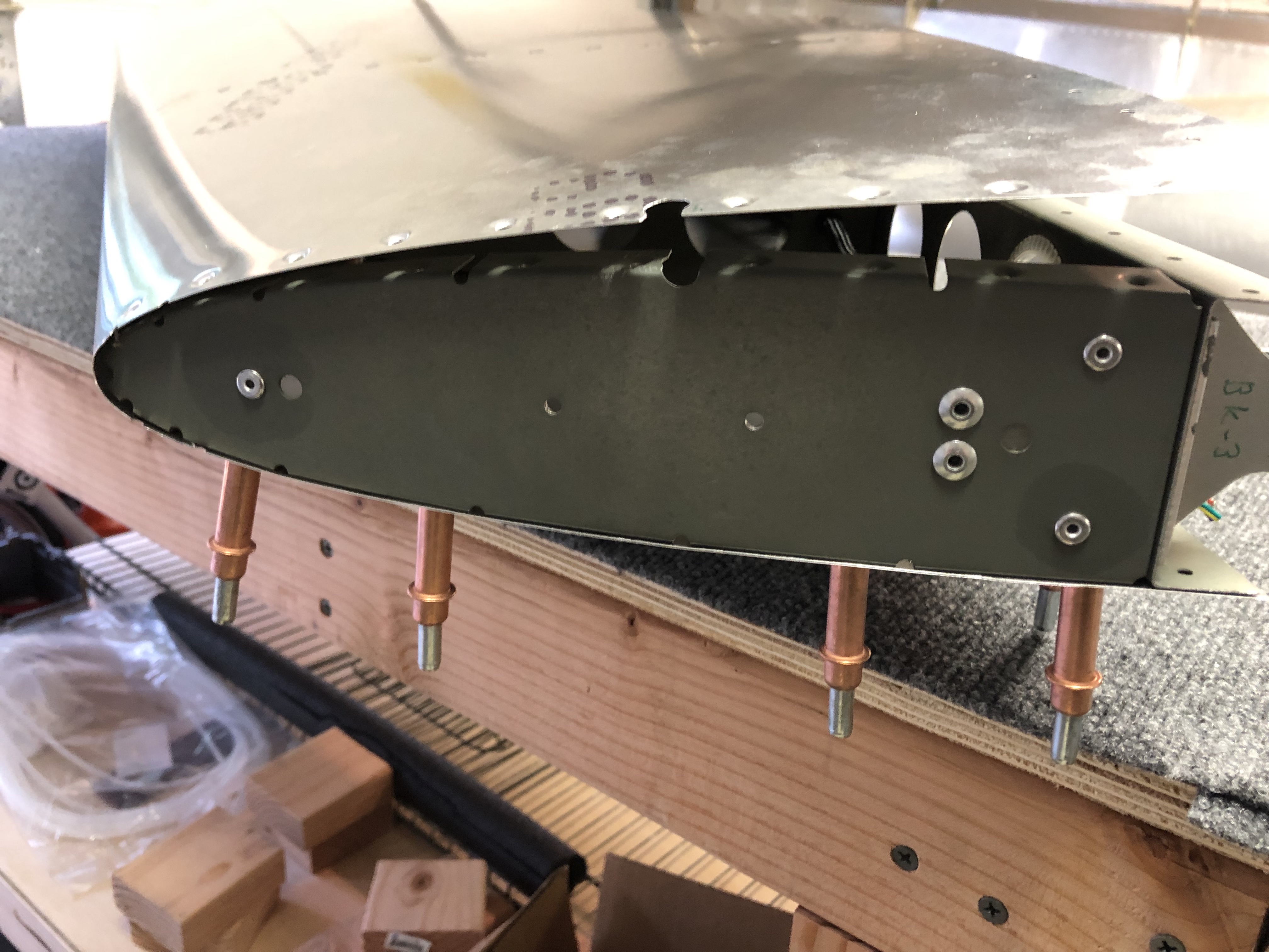
With the wiring finished and the Antenna fitting done, I am now finally able to close up the Vertical Stabilizer and rivet the skin.
To begin, I closed up the left side of the skin and held it in place with clecos, since this is the side where the Antenna slides through the enlarged rivet hole, while on the right side I had to create the custom notch so that I can pull the skin around the Antenna.
Once that was done, I riveted on the support plate for the Antenna onto the top rib of the Vertical Stabilizer.
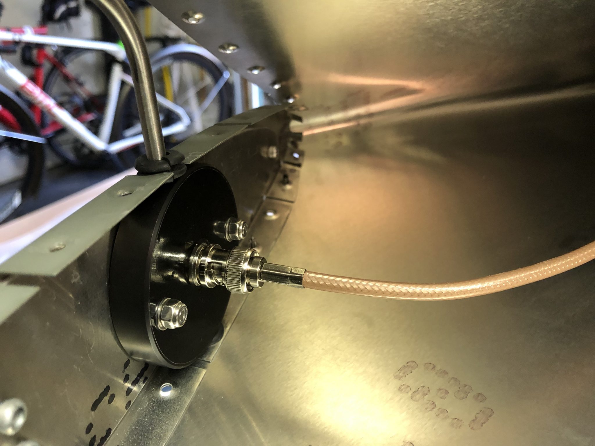
Now that the structure is complete, time to mount the Antenna permanently in place. Using two 20mm long M4 screws, washers and Nyloc nuts and some medium strength threadlocker I mounted the Antenna in place. Here’s the Antenna mounted in place and the wire connected to the Antenna using the BNC connector I crimped onto the wire.
Riveting the skin
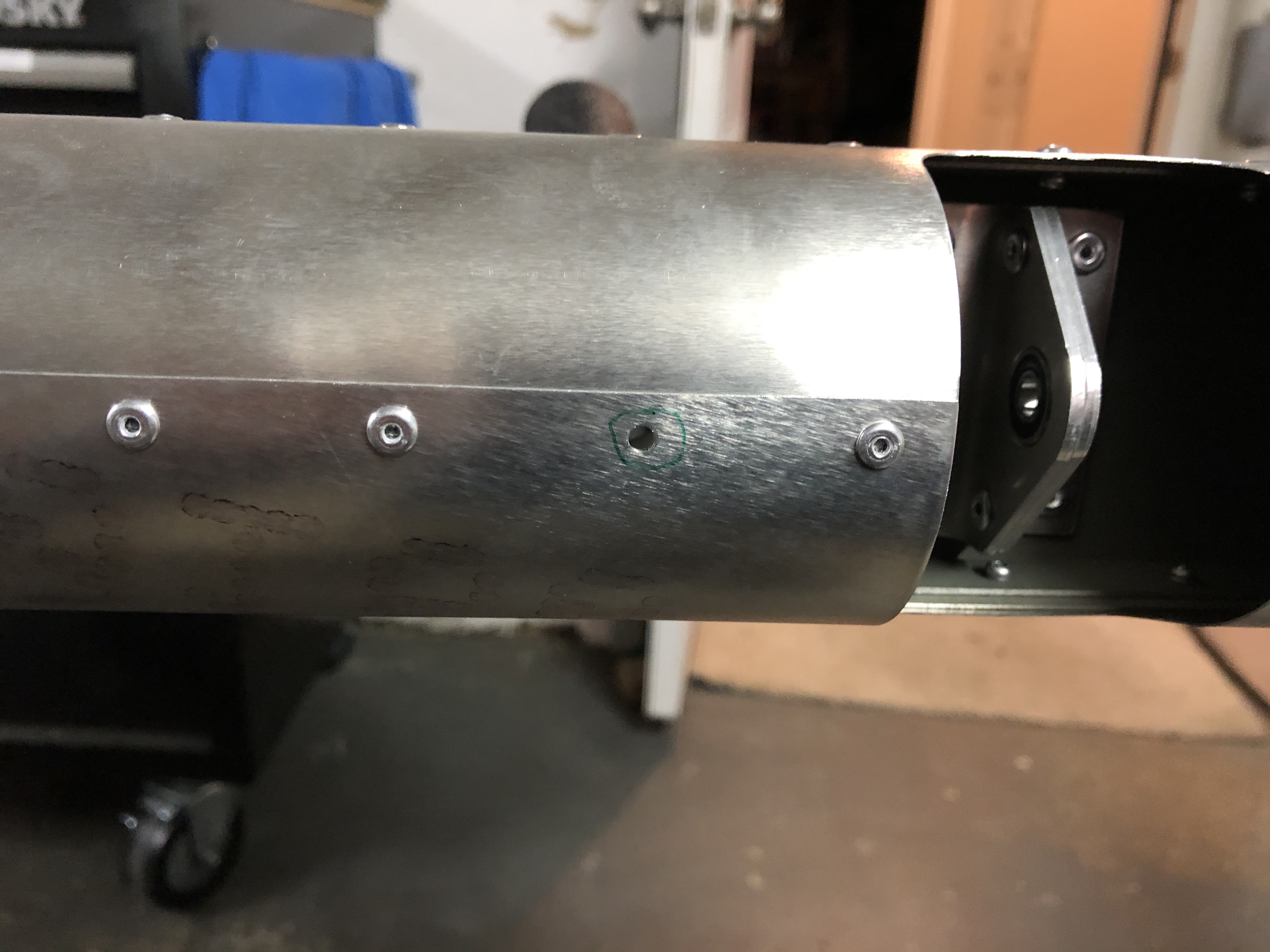
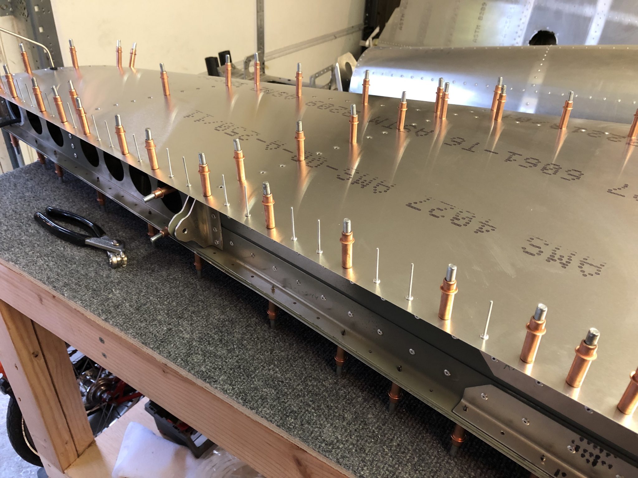
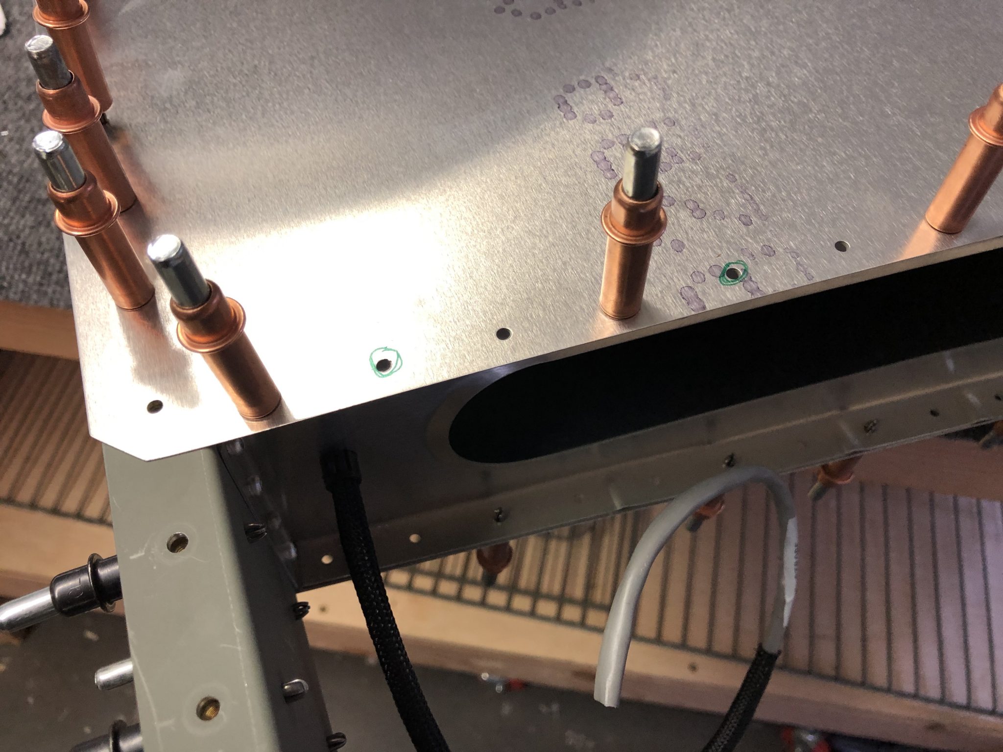
With all the prep work finished, I closed up the right side of the skin, made sure everything fits correctly and clecoed it in place. There are two holes on the bottom on each side that are not riveted, but instead I have to install Rivnuts in them, so I marked out those holes, so I don’t accidentally rivet them.
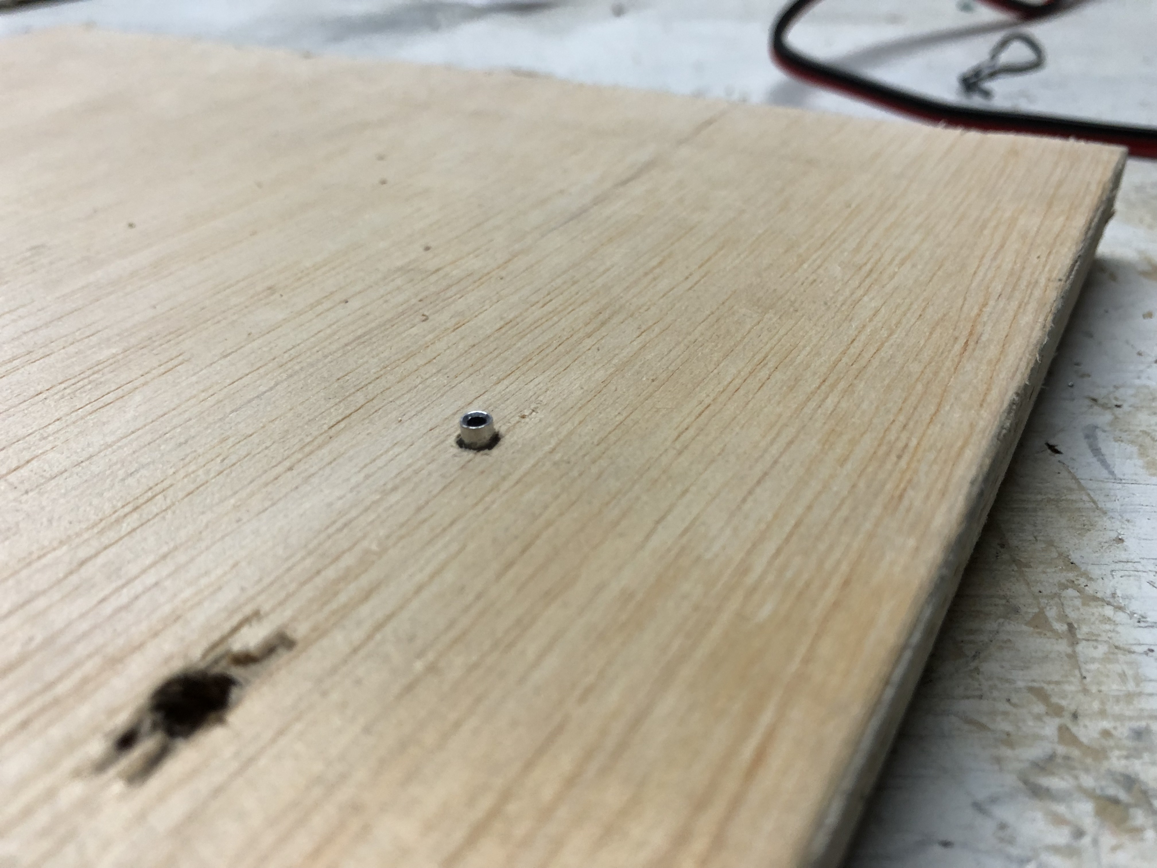
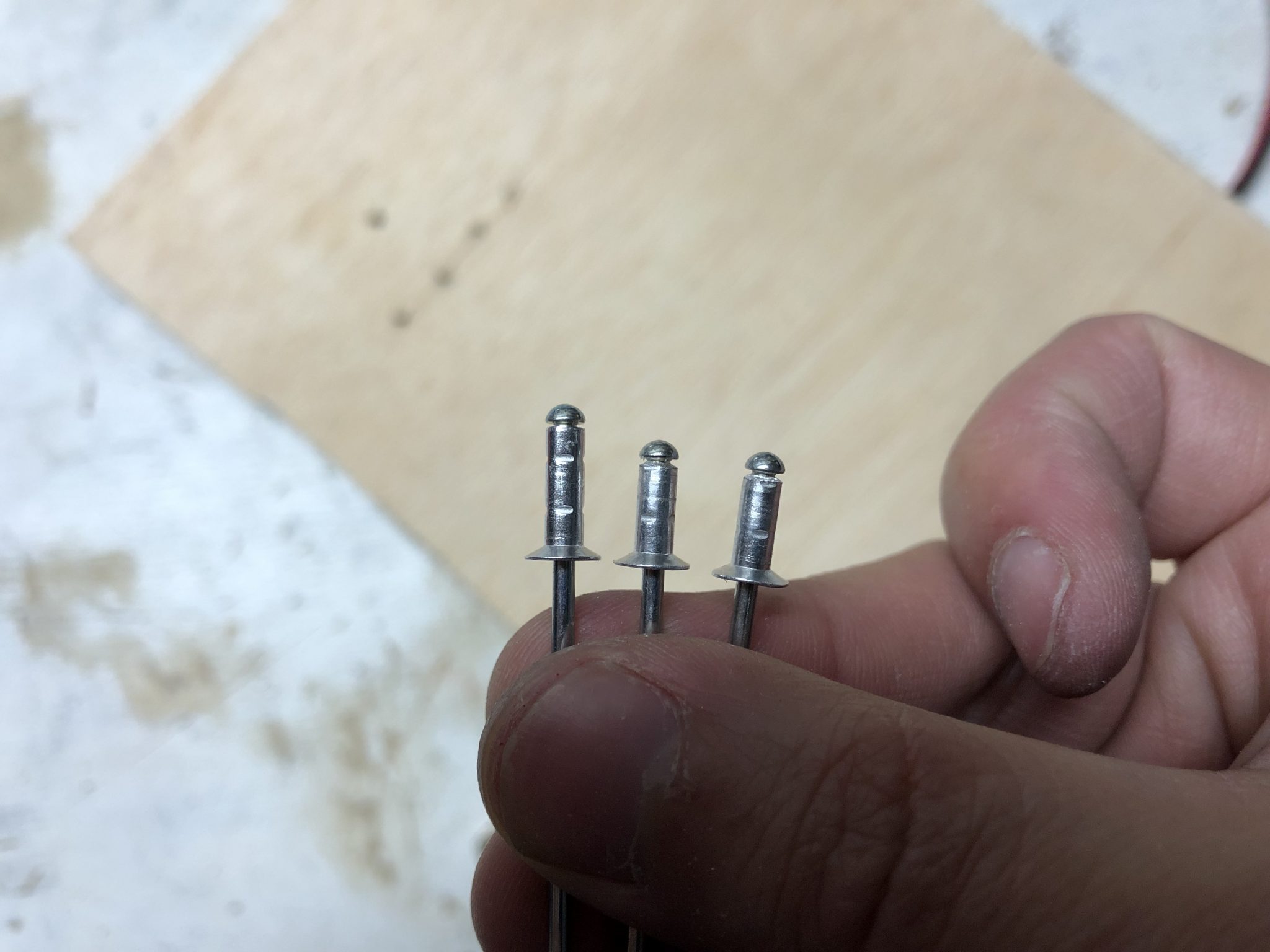
There were two rivets that I had to shorten in order for them to fit flush near the Antenna. So I made a small template for the dept through a piece of wood and then shortened them accordingly.
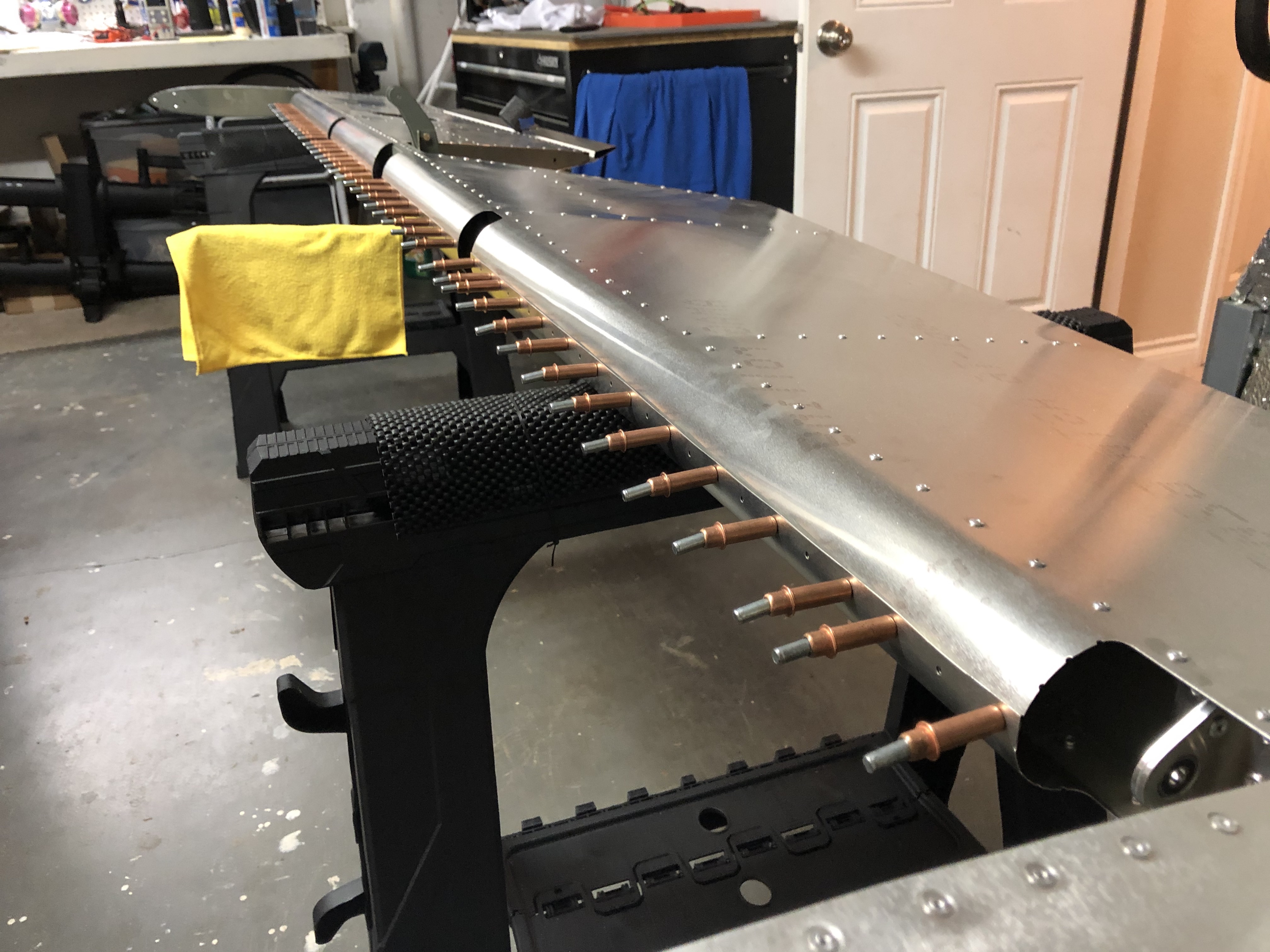
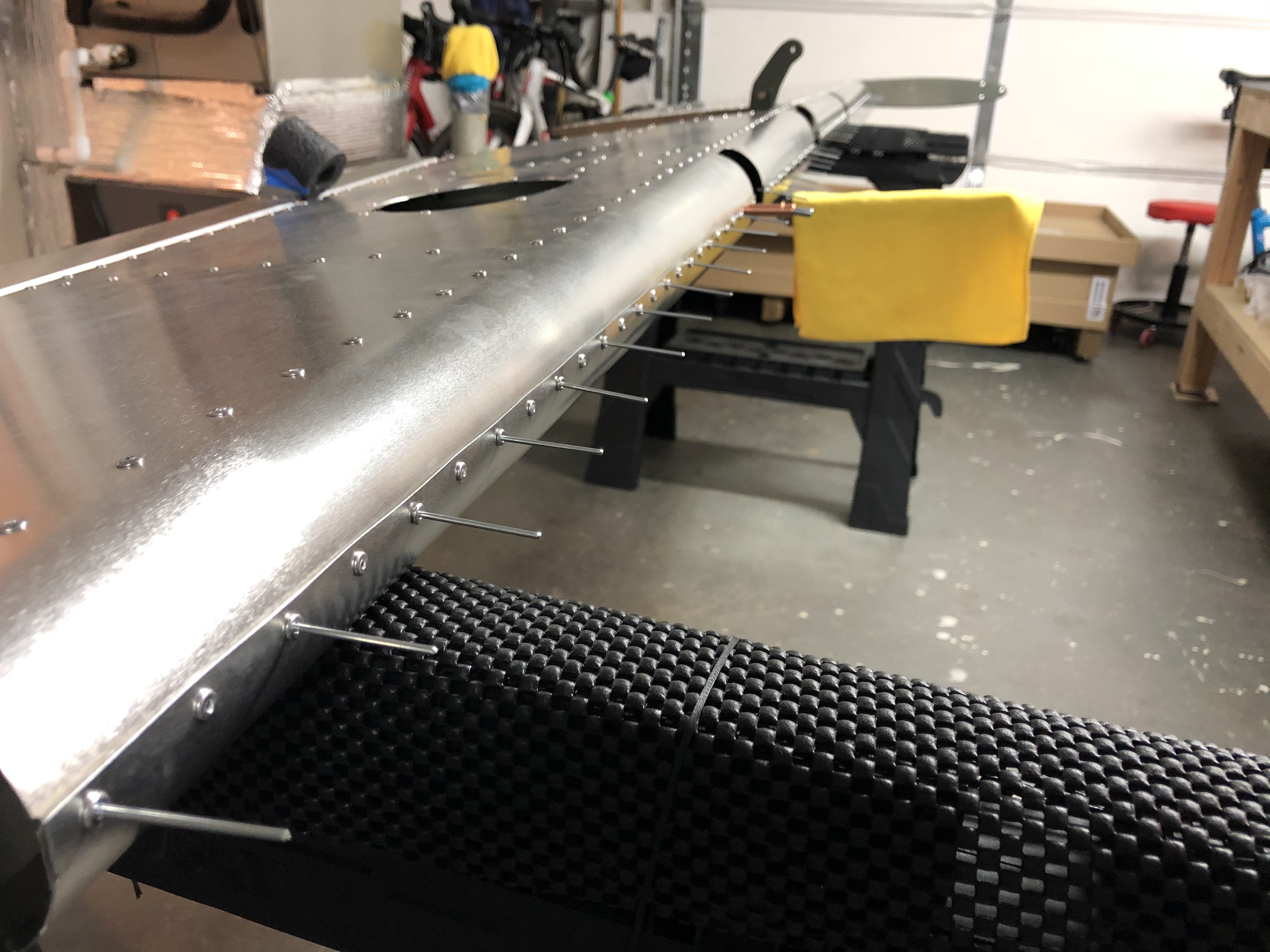
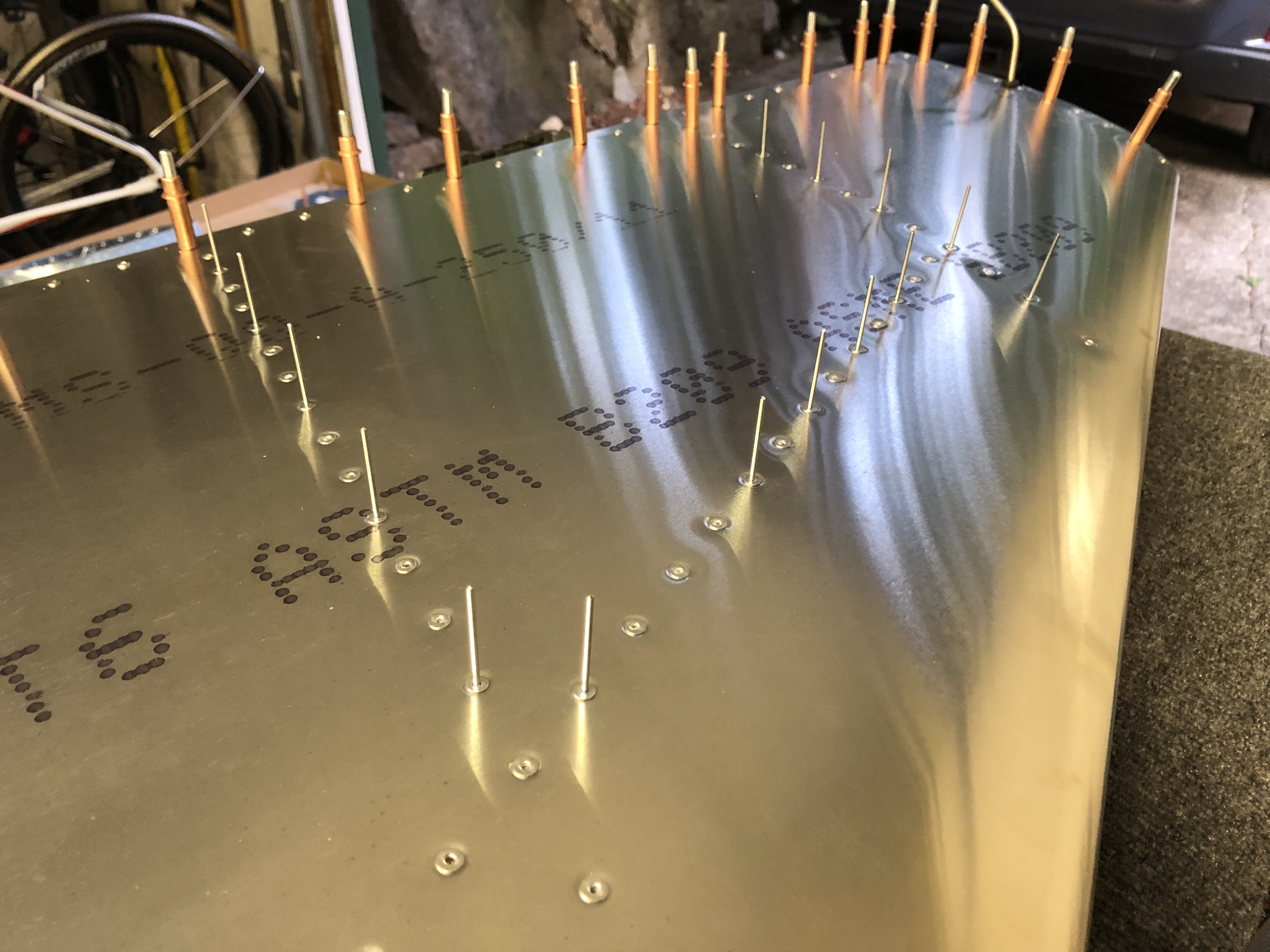
After that, it was just a matter of pulling the many rivets on both sides of the skin to close the Vertical Stabilizer up for good.
The last part was to install the two rivnuts on the bottom on each side, so after enlarging the holes using my step drill and reaming them out using my hand reamer, I got out my rivnut puller and high strength loctite and put those in place.
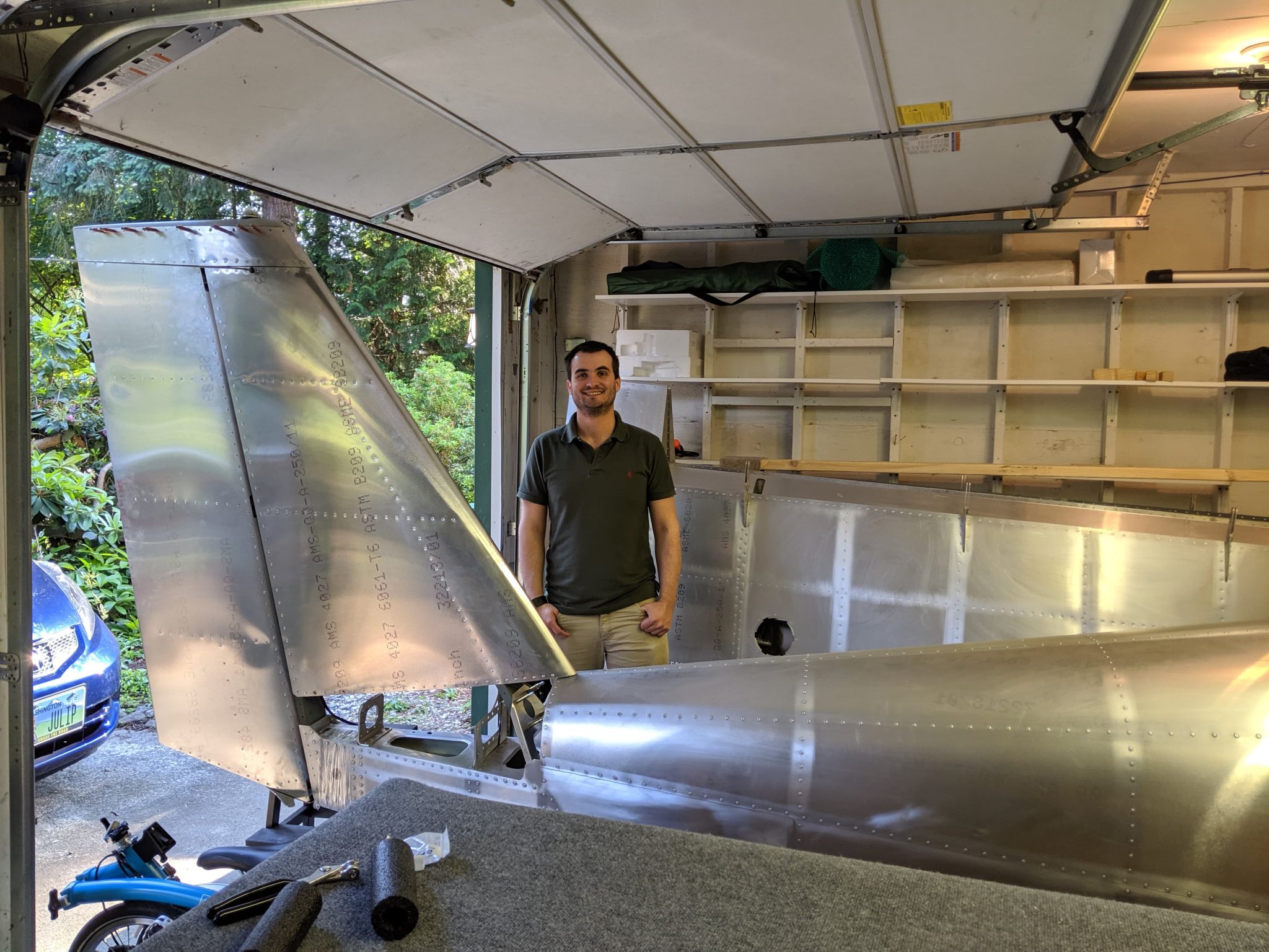
With the Vertical Stabilizer completed, I then did a quick test fit and mounted it on top of the Fuselage and also attached the Rudder for a moment – almost looks like an airplane.
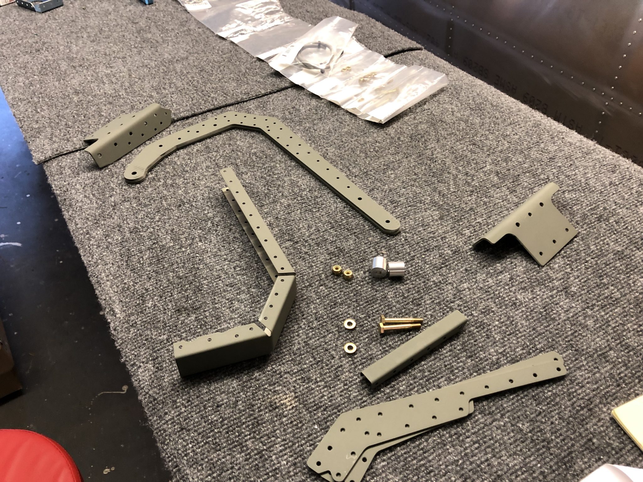
While I was waiting for some parts to complete the ribs for the Vertical Stabilizer, I got started working on the Elevator. Since there are a lot of parts to the Elevator I broke it down into smaller tasks, first preparing the parts of the center counterweight and then I’ll continue next with the other parts of the structures.
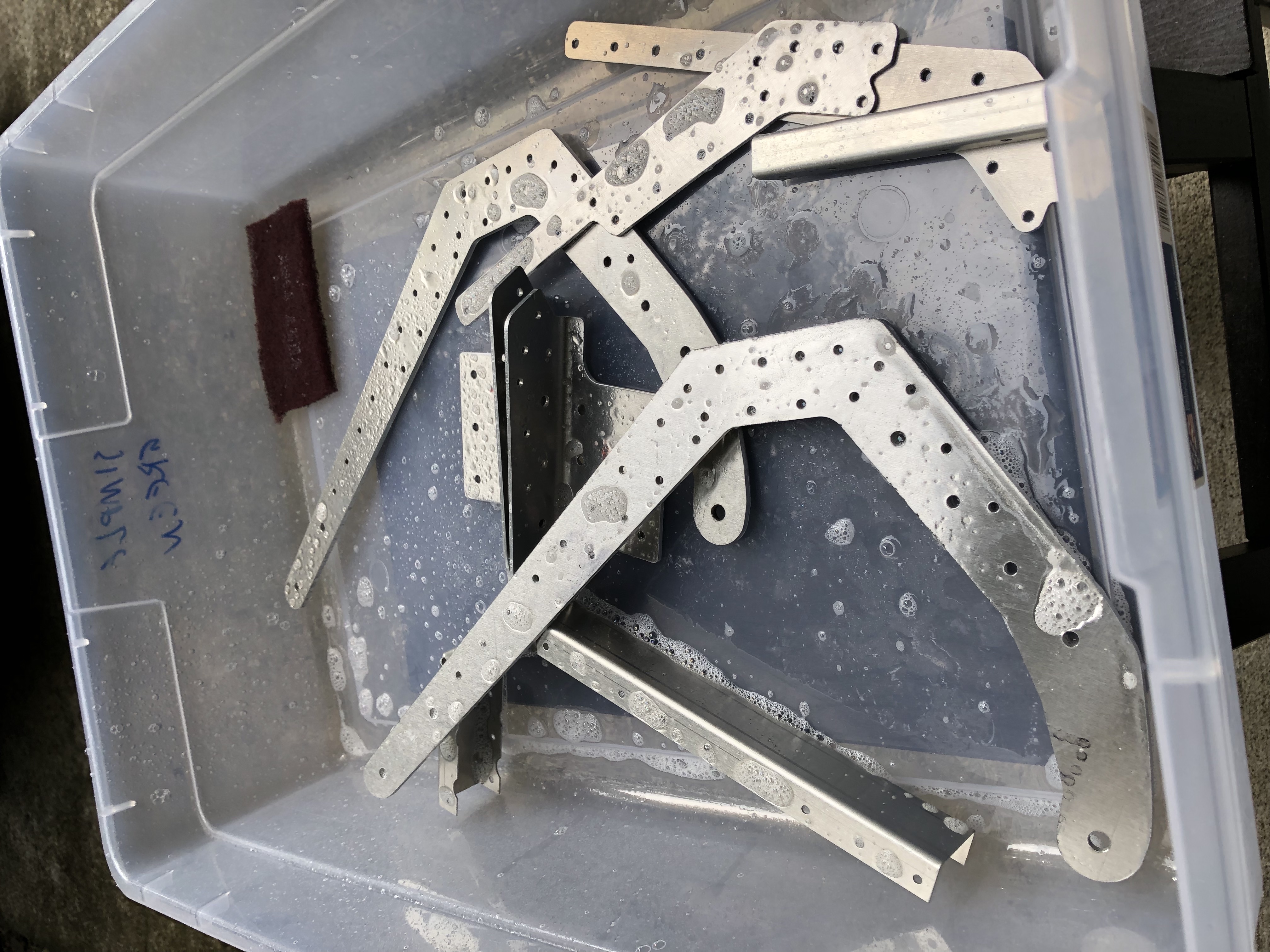
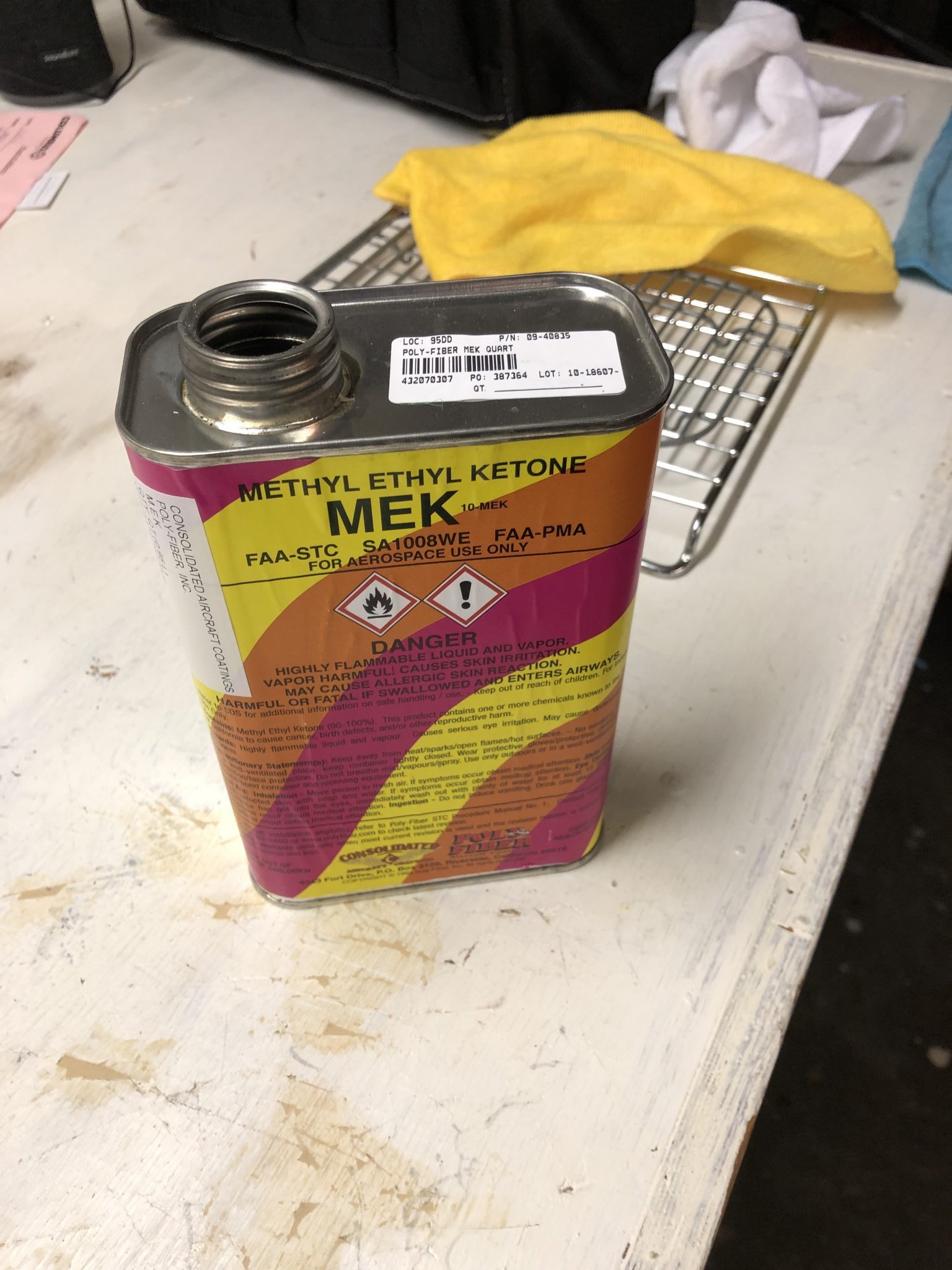
So onto another session of preparing the parts, deburring holes and edges and cleaning with Simple Green & degrease with MEK. After that was all done it was back into my small paint booth to prime everything.
Riveting the Elevator Counterweight
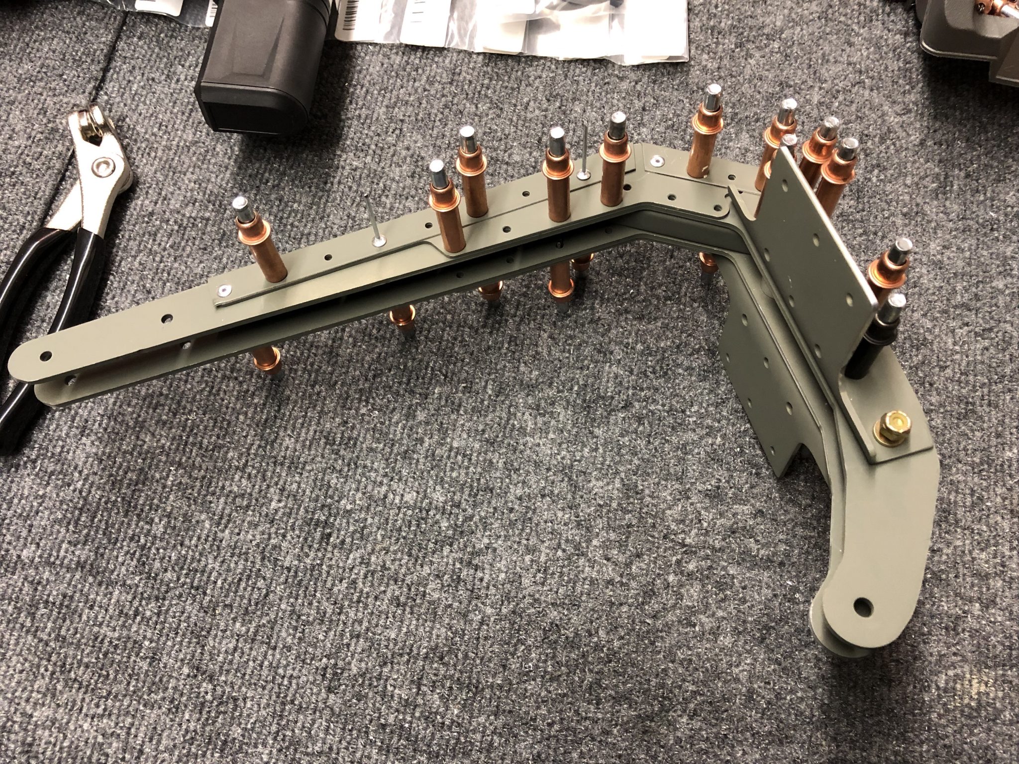
After all that had time to cure for a day I went to work to put together the center counter balance weight support (that’s a mouthful). I found a small error in the instructions that say that there are 14 rivets in the center, but it’s actually 16 rivets. Sometimes with these small errors I wonder if they are intentional to keep us builders on our feet to make sure we “measure twice and drill once” – I sent the Factory a note to correct the error in the instructions for the next iteration.
So after I laid out all the parts I put everything together using clecos and the two AN3 bolts and then went to work riveting it together. A friend was visiting from Ireland as well, so after a tour of the garage and everything he also pulled his first rivet and I had him sign his name under it.
Rudder Timelapse video
I also recently finished editing together the work on the Rudder, so here’s the completed Timelapse video:
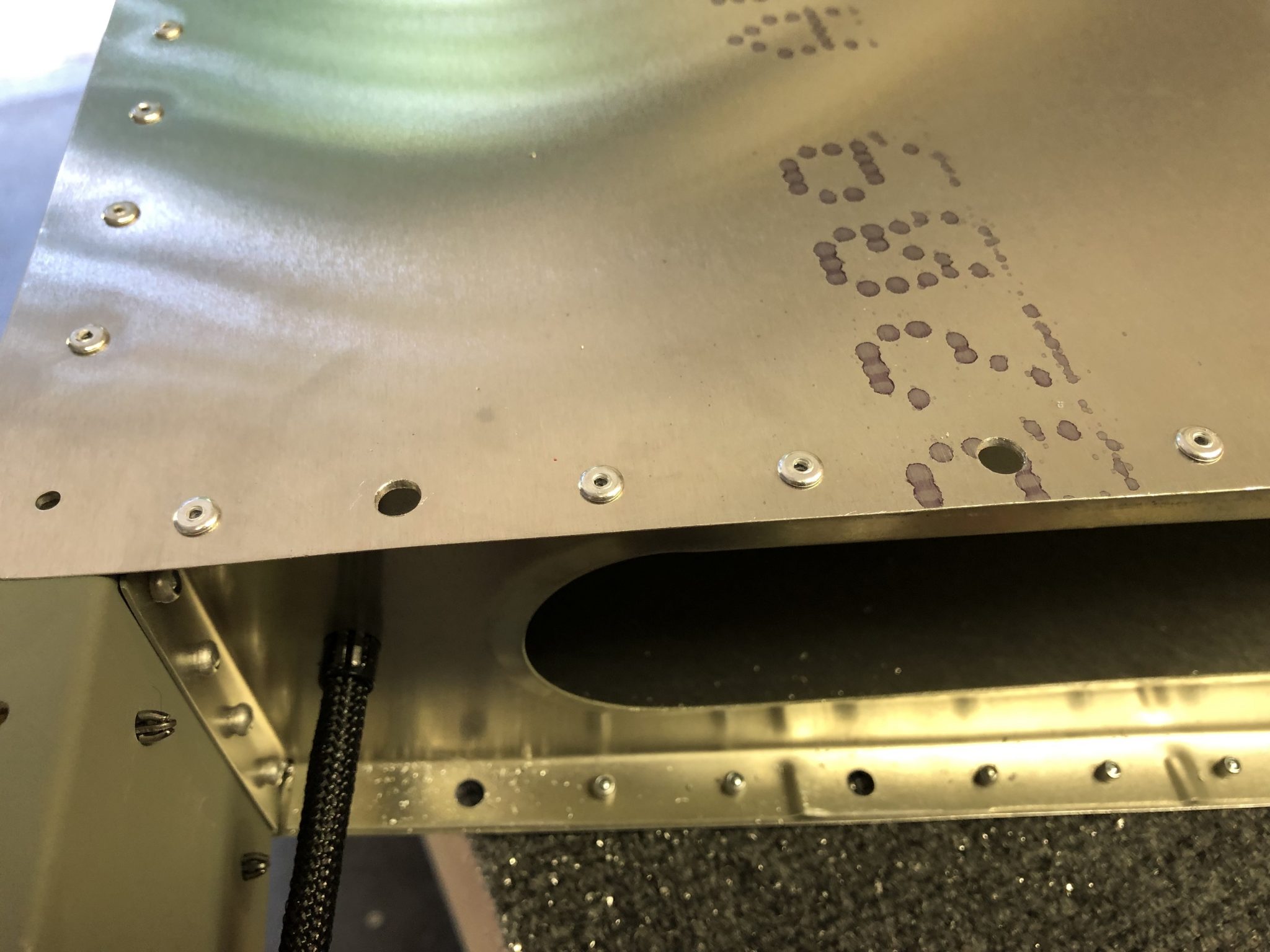
The pop dimpling tool that I ordered a few days ago arrived on Friday, so I spent some time trying it out to make sure it worked properly so I could finish adding the missing dimple to the skin and finish closing up the Horizontal Stabilizer.
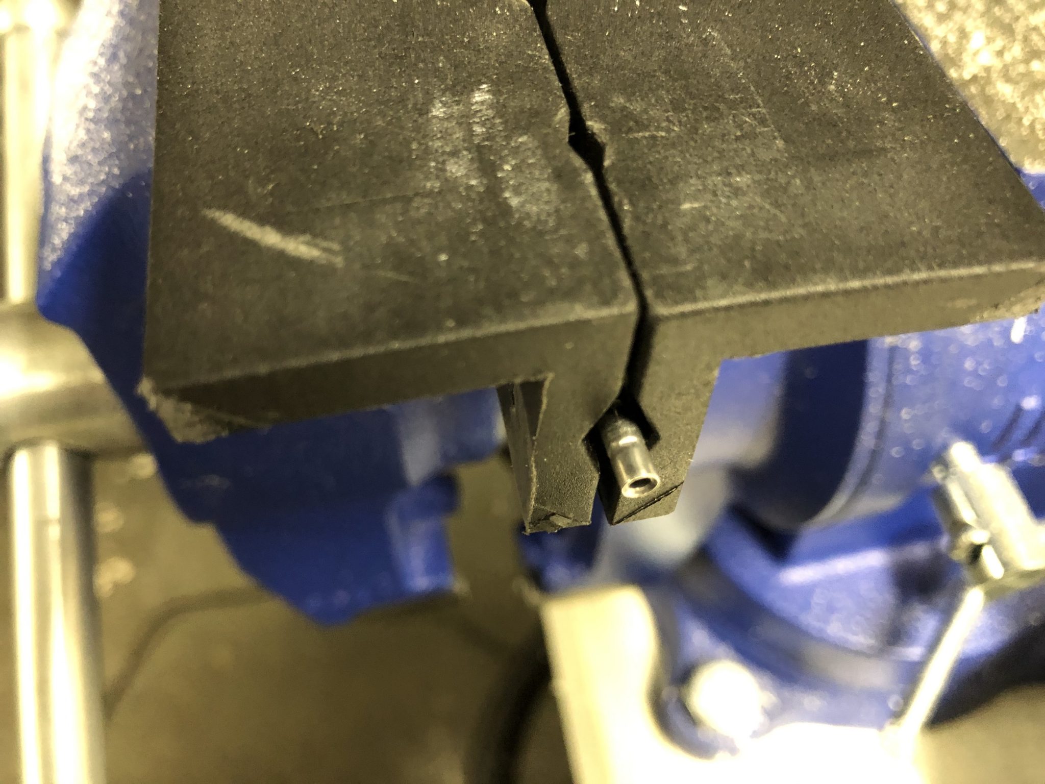
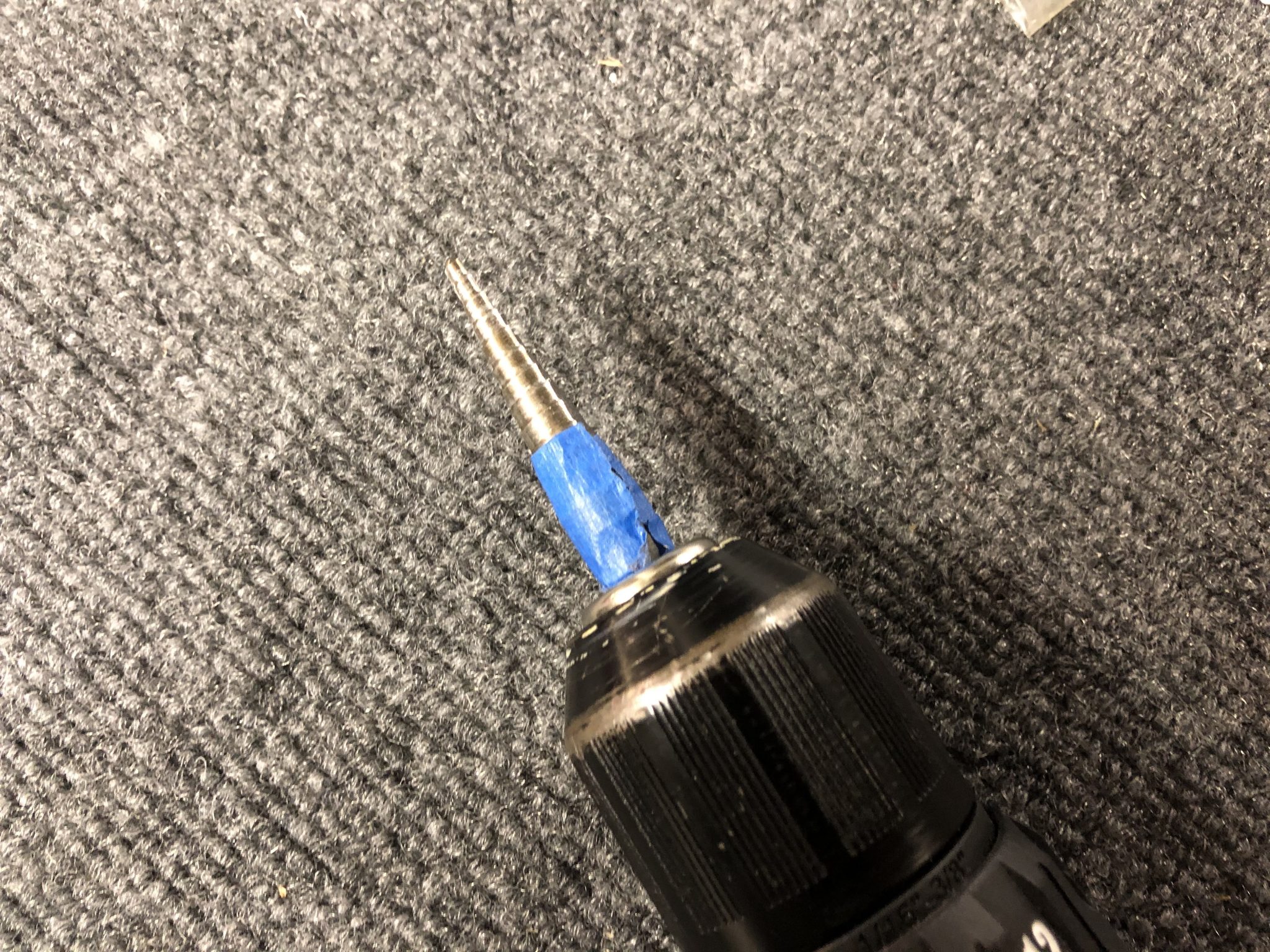
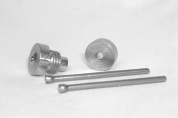
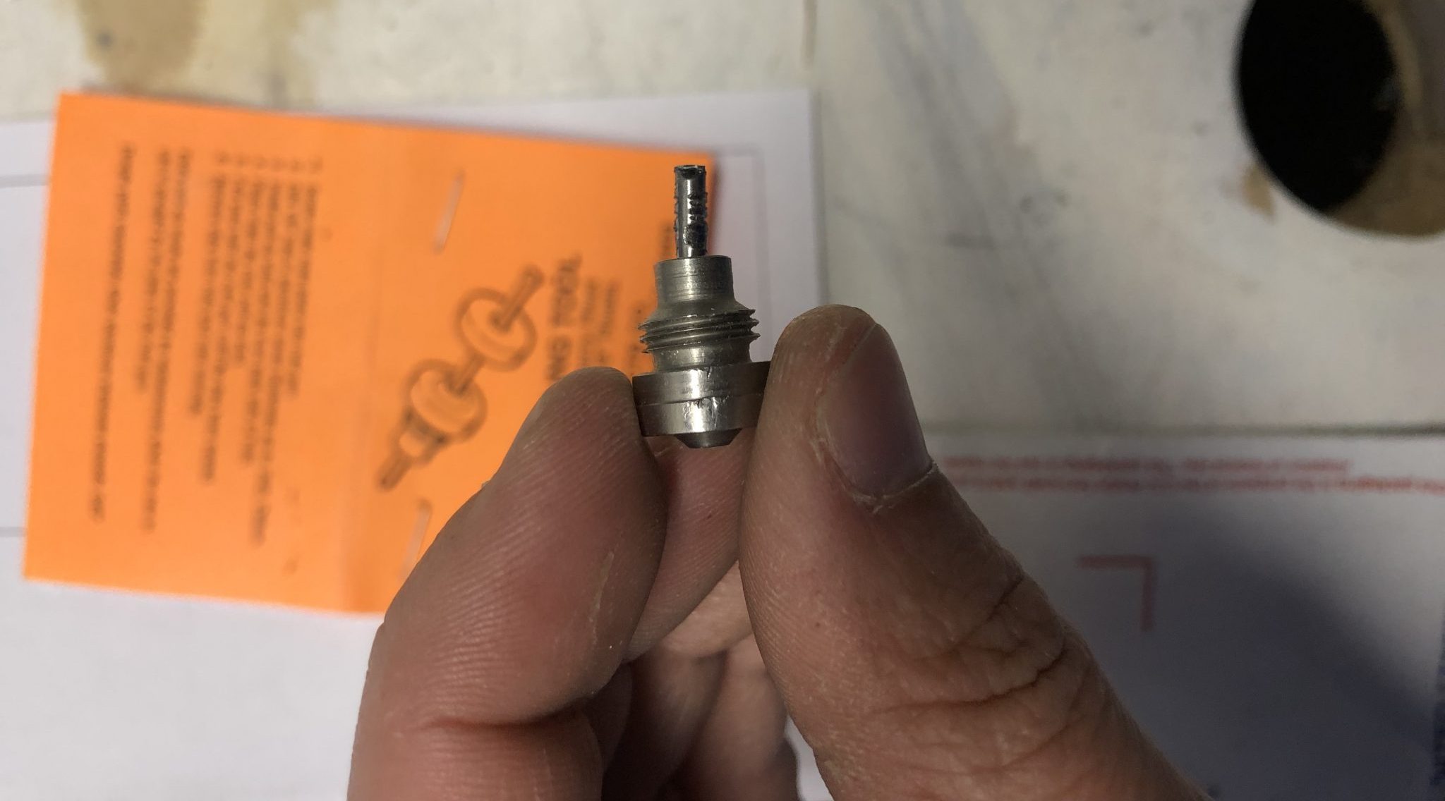
After a bunch of research on them, I actually ordered 2 different tools, one is made by Aircraft Tool Supply and creates a 100 degree dimple, and the other one promises to create a 120 degree dimple, I’m not sure who exactly actually makes it, but it’s sold via Wicks Aircraft tools. The 120 degree tool from Wicks is DT-17014 and it’s supposed to screw into a G28 hand riveter. Unfortunately the Hand Riveter I own seems to have smaller threads than the G28 hand riveter, so I decided to try it on my Milwaukee rivet gun which had the correct thread size. As I found out when I pulled with it, that ended up with too much force, so the head of the stem (which is a finishing nail) that is supposed to hold the back of the dimple in place actually deformed and got pulled into the top and got stuck.
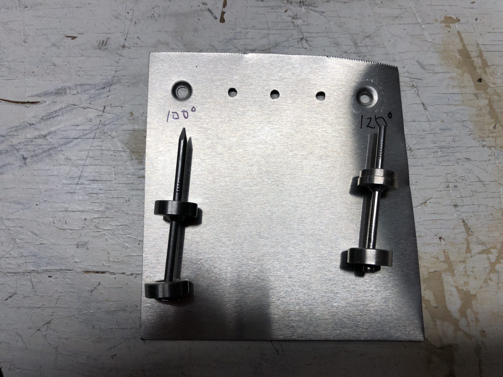
So after that happened, I had to cut off the nail, but I couldn’t pull it out of the tool, so I got out my Dremel and cut off the top part of the bit where the deformed head got stuck in. This way I could try to use the tool like the ATS pop dimple tool (5102D-1/8) works, which just sits on top of the rivet puller. ATS tool on the left and the other one on the right (after I cut off the top):
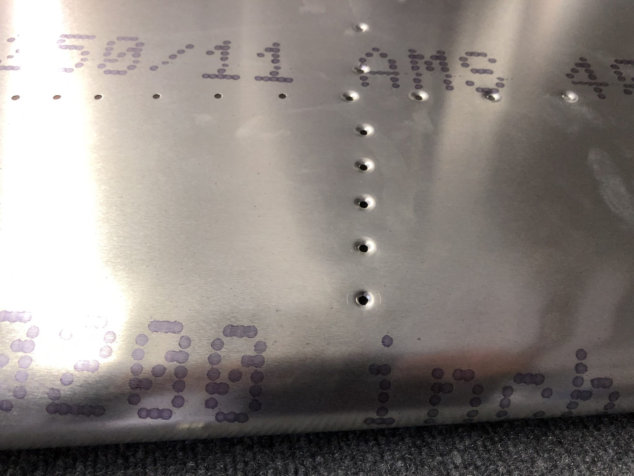
So now after that modification to the tool, I tried both by holding my test piece onto the existing dimples of the Horizontal Stabilizer and determined (as expected), that the 120 degree dimple has the better fit, so I used that one to make the dimple to the skin. It came out well and the countersunk rivet sits flush like the other dimples. So for one or two dimples, this works out nice and easy and I didn’t have to go and get a dimpling press.
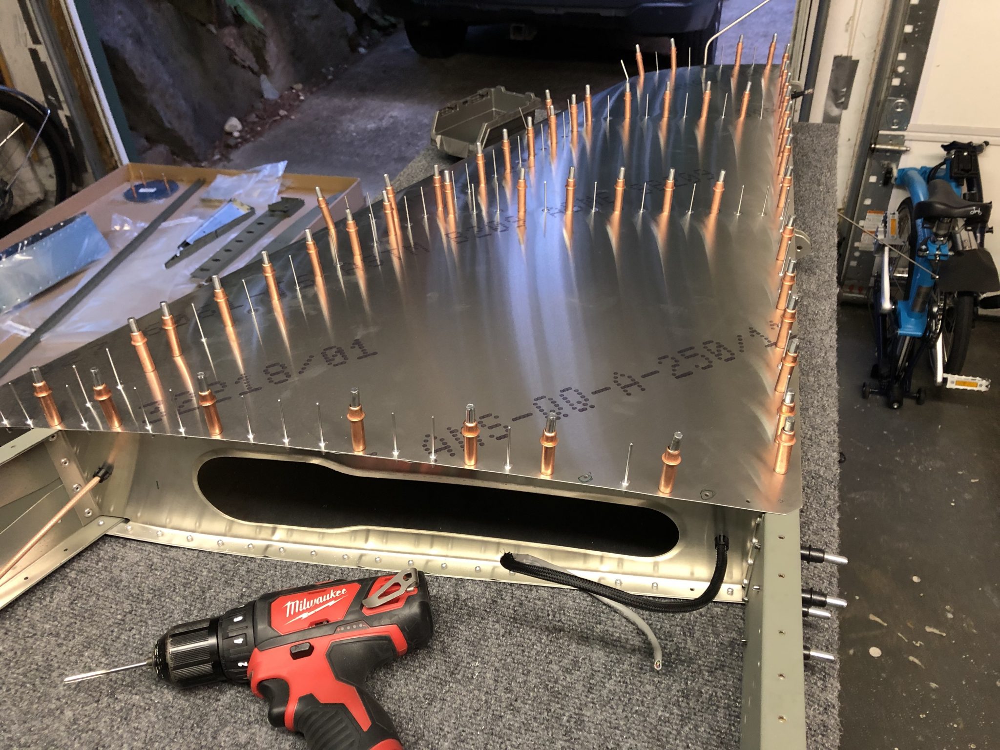
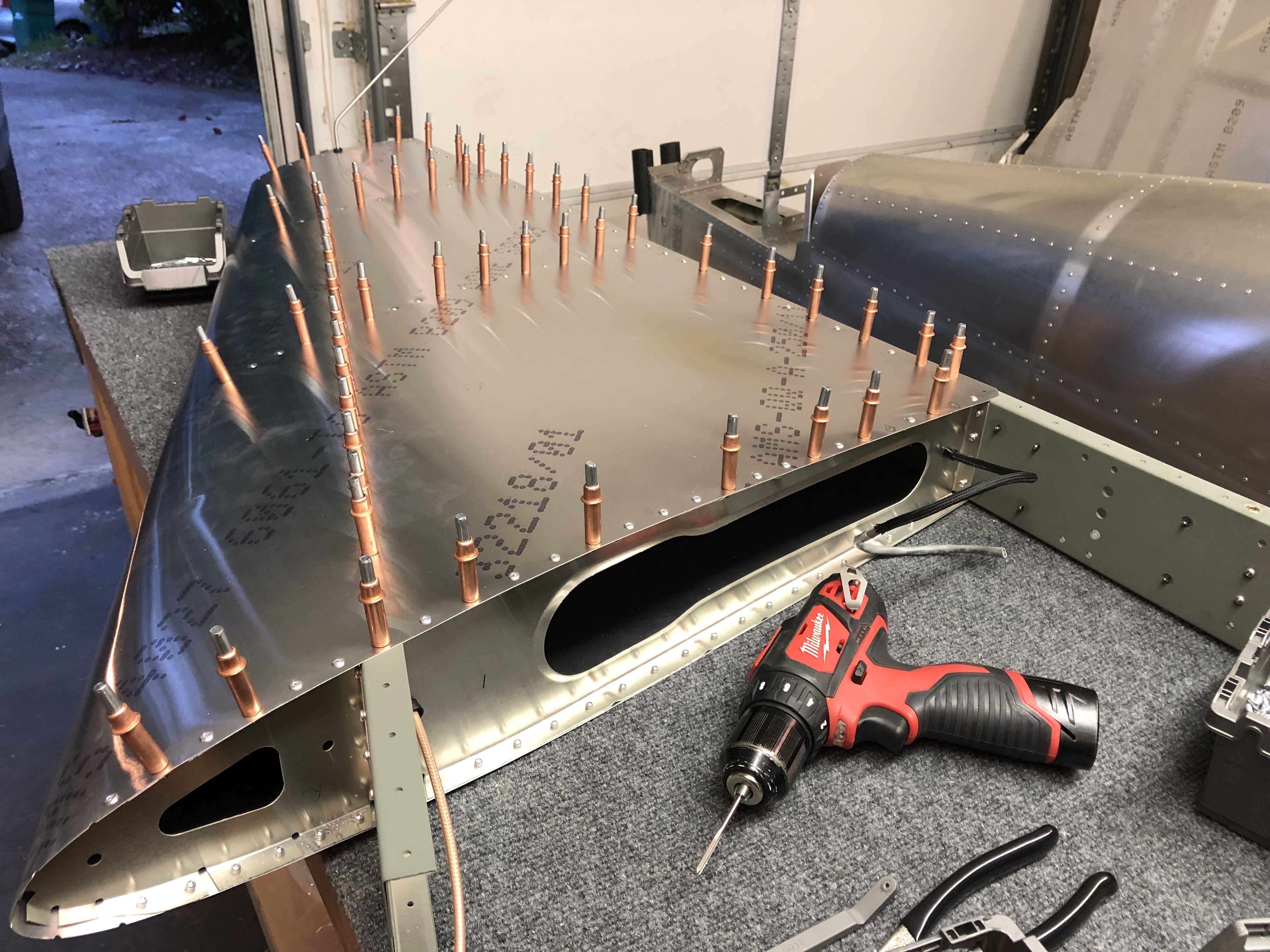
Riveting the skin
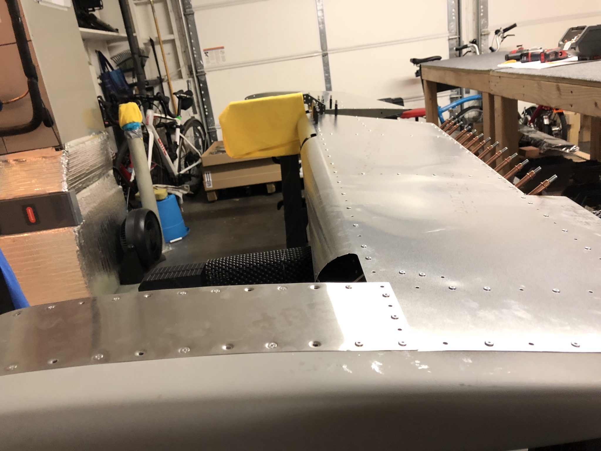
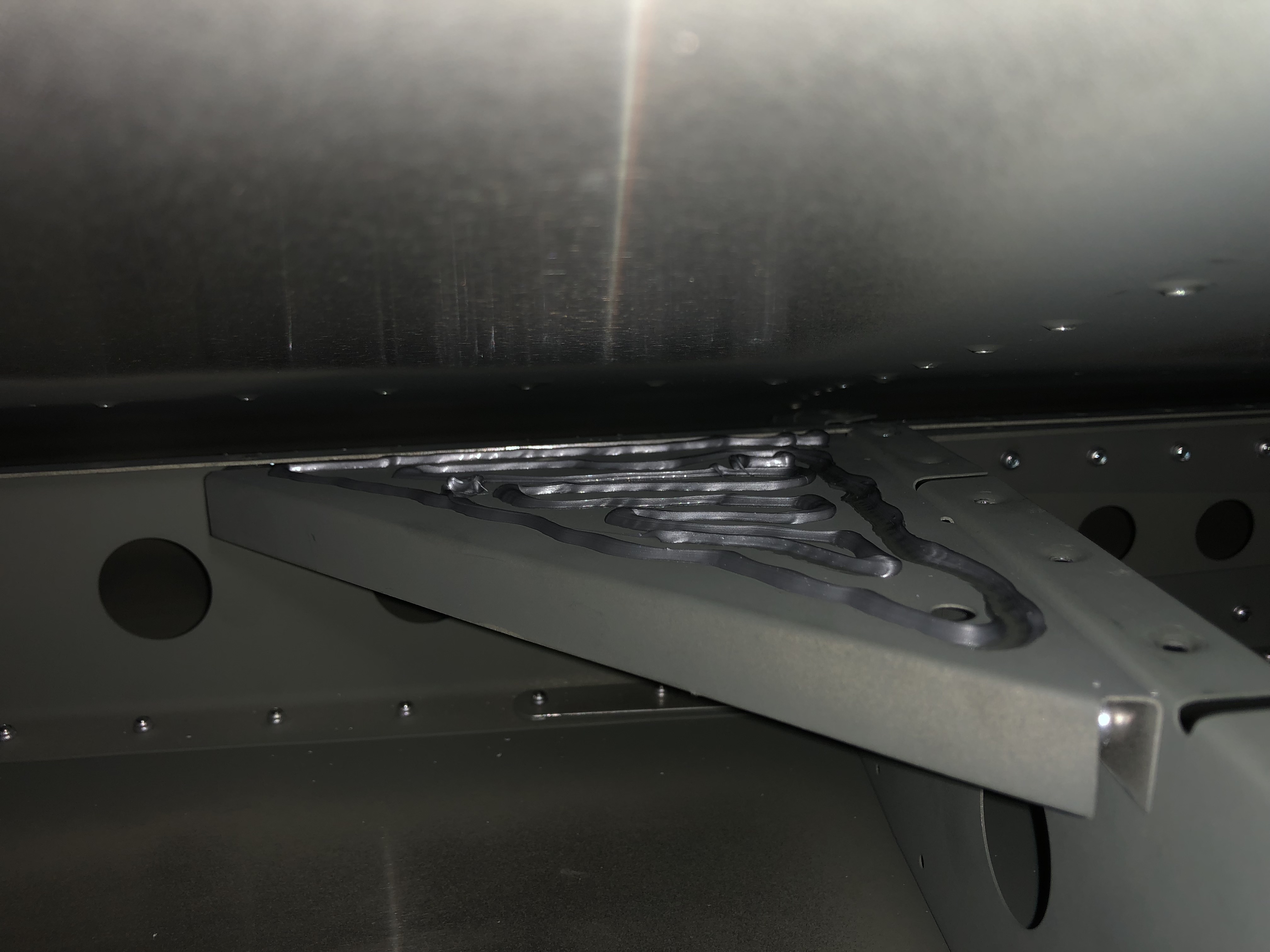
Once all that was said and done, I got to work and riveted the complete bottom of the left side skin. Then turned it around, removed all the Clecos from the top side one last time so I could apply the Sealant to the support plate like I did on the other side. And then I finished up riveting the top side.
20190323_185614013_iOS
Bottom left side riveted together
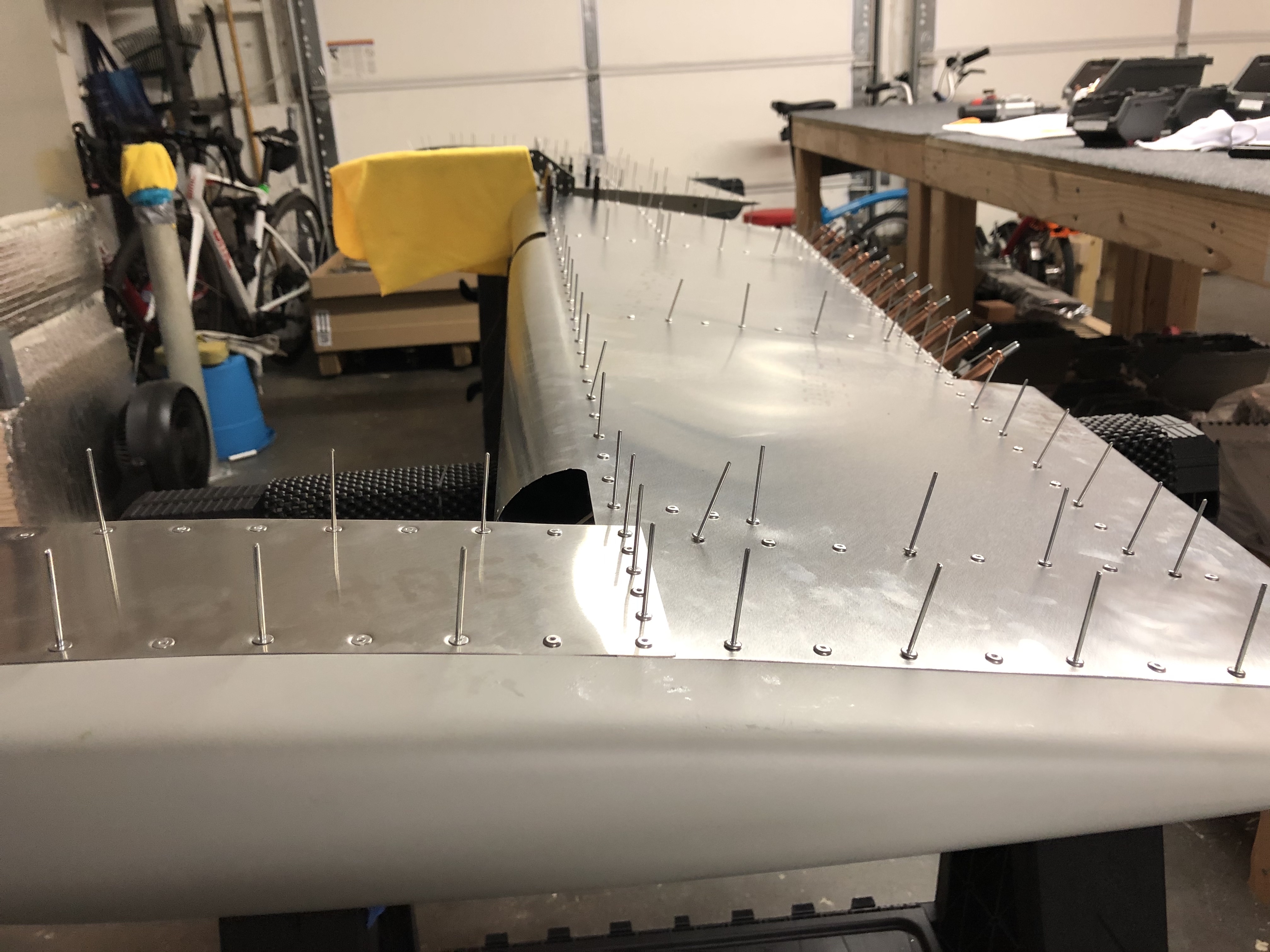
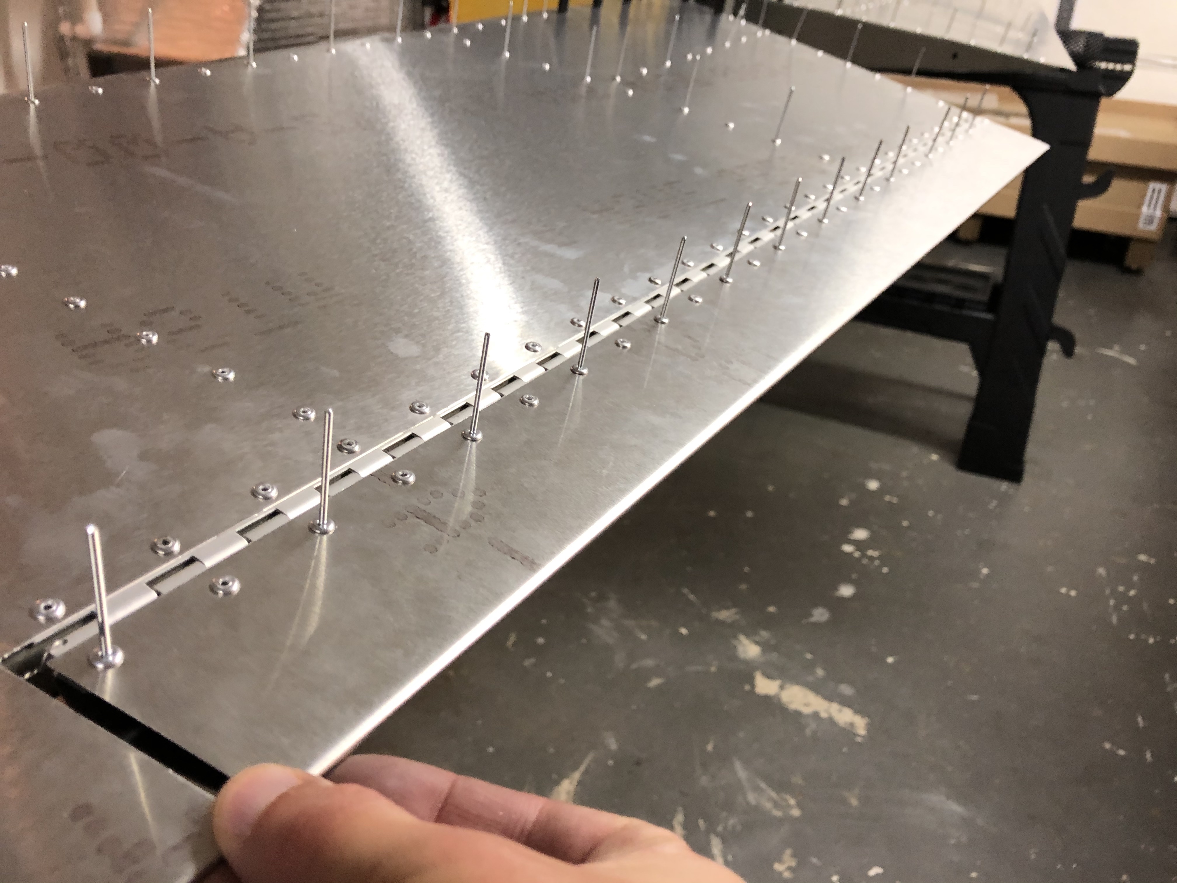
Top left side ready to rivet
Sealant applied to the support plate
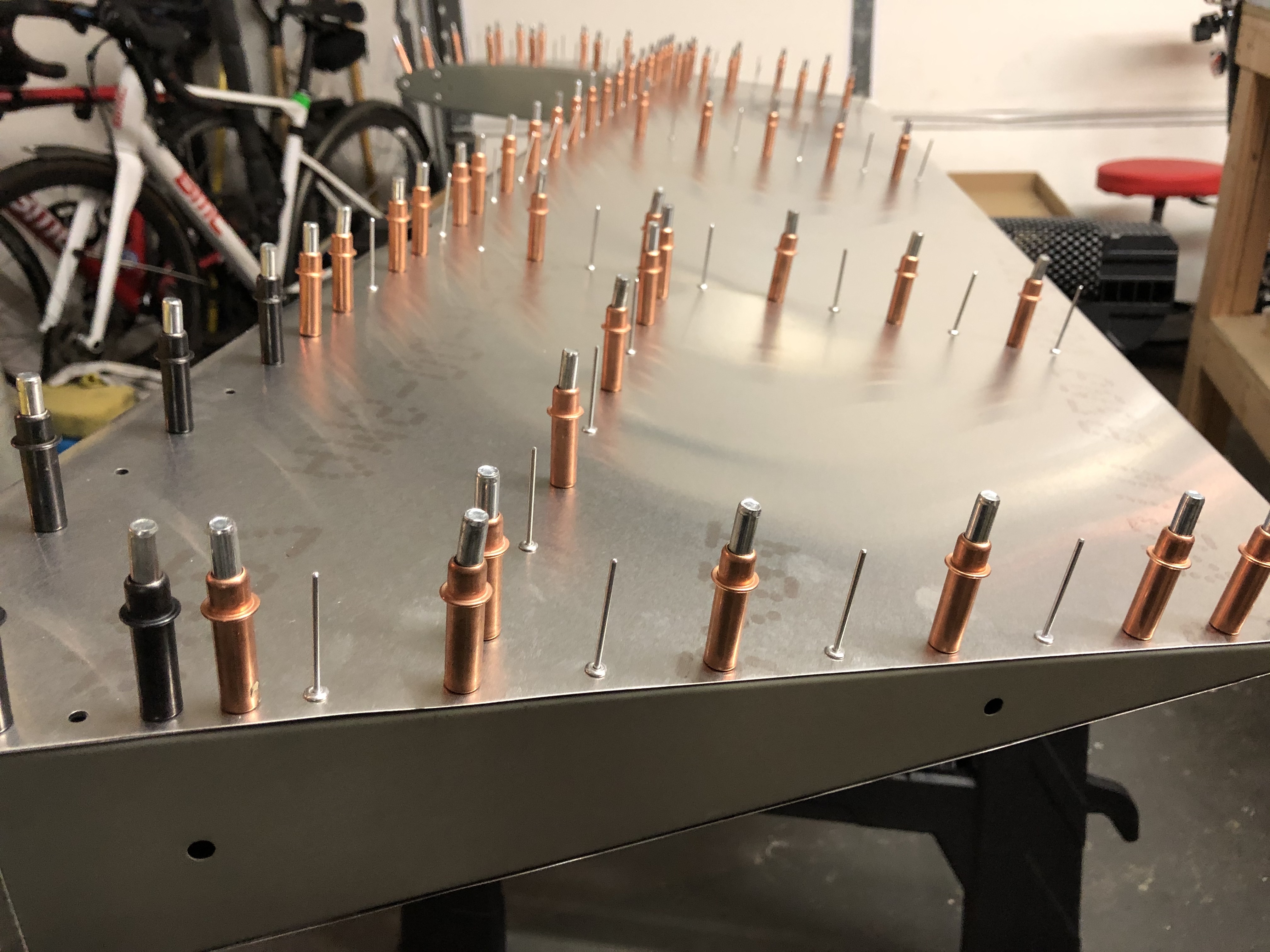
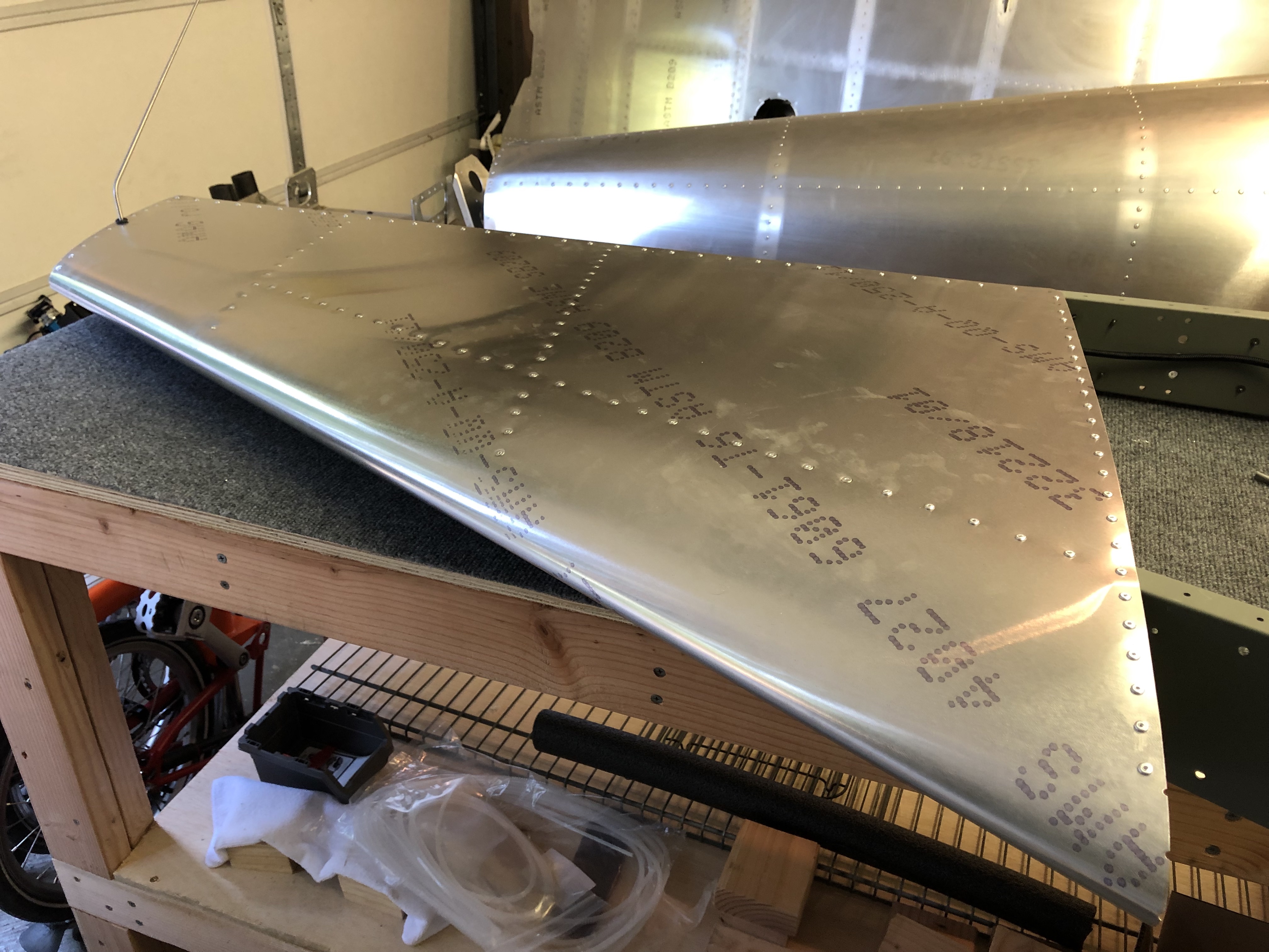
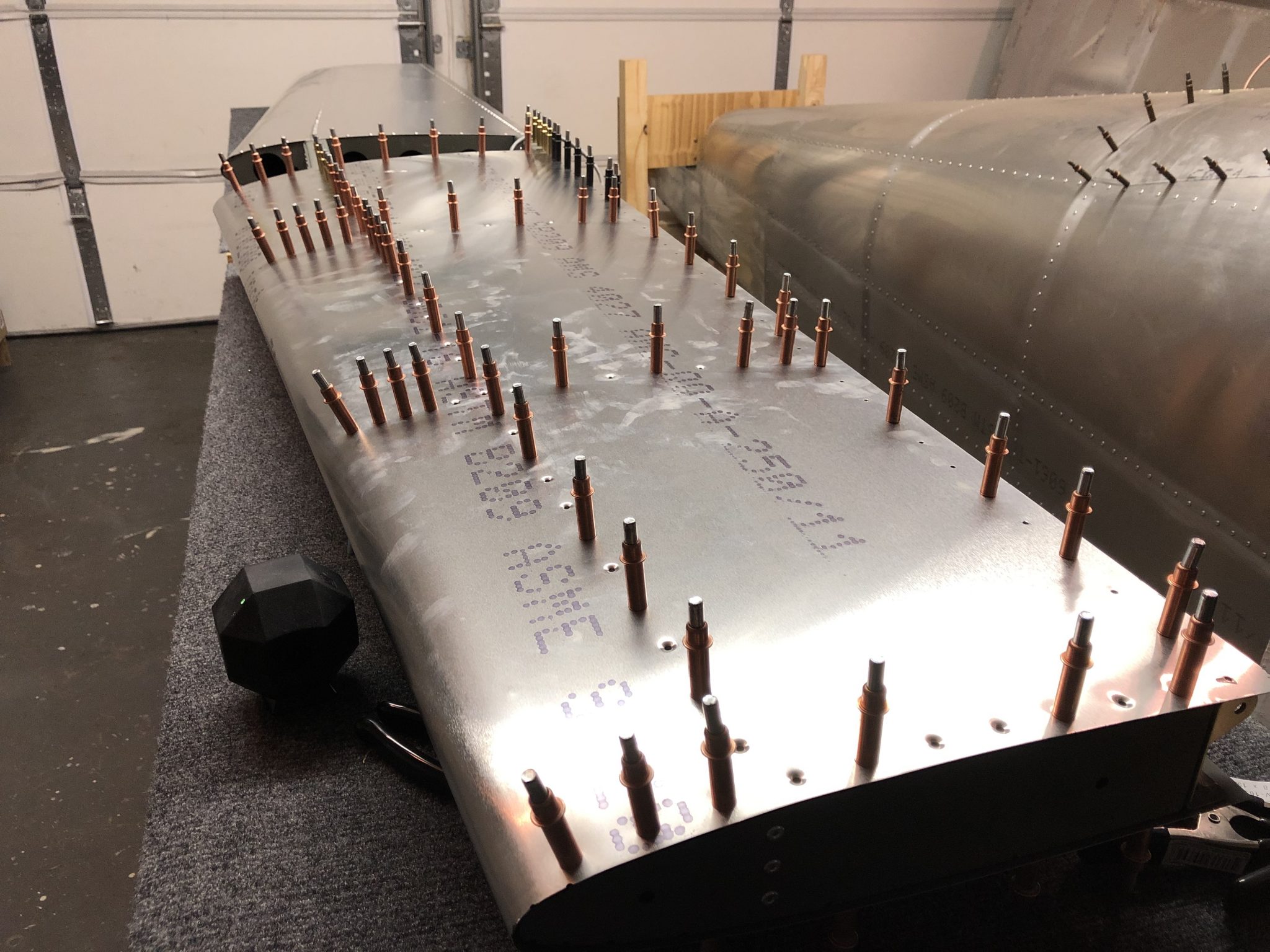
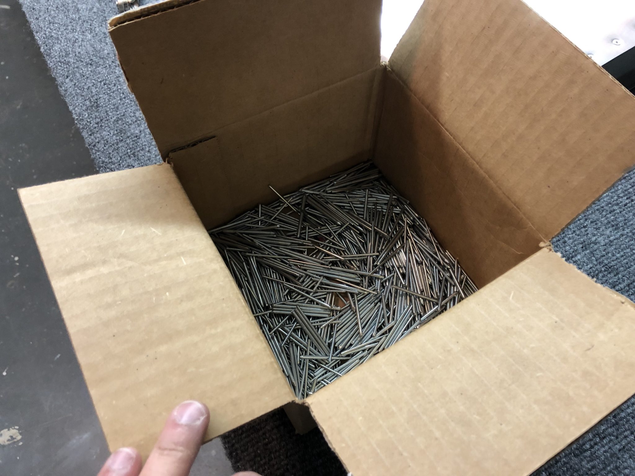
A few hundred rivet stems after all the riveting of the Horizontal Stabilizer was done
Finished riveting the Horizontal Stabilizer
Timelapse Video of Finishing the Horizontal Stablizer
And lastly as promised, here’s the timelapse video of the whole endeavor of the Horizontal Stablizer.
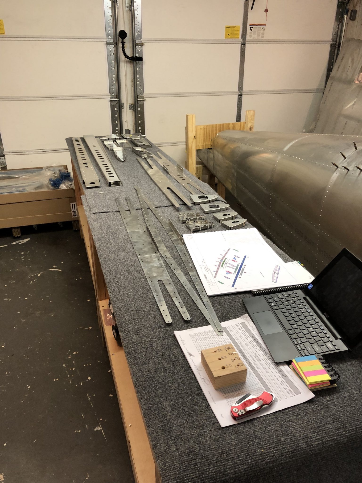
When we took inventory of the Empennage kit, we thought we were missing some parts of the Elevator and so I decided to start with the Horizontal Stabilizer instead, but as it turned out after double checking again, the parts were just hiding inside a channel.
Parts Prep
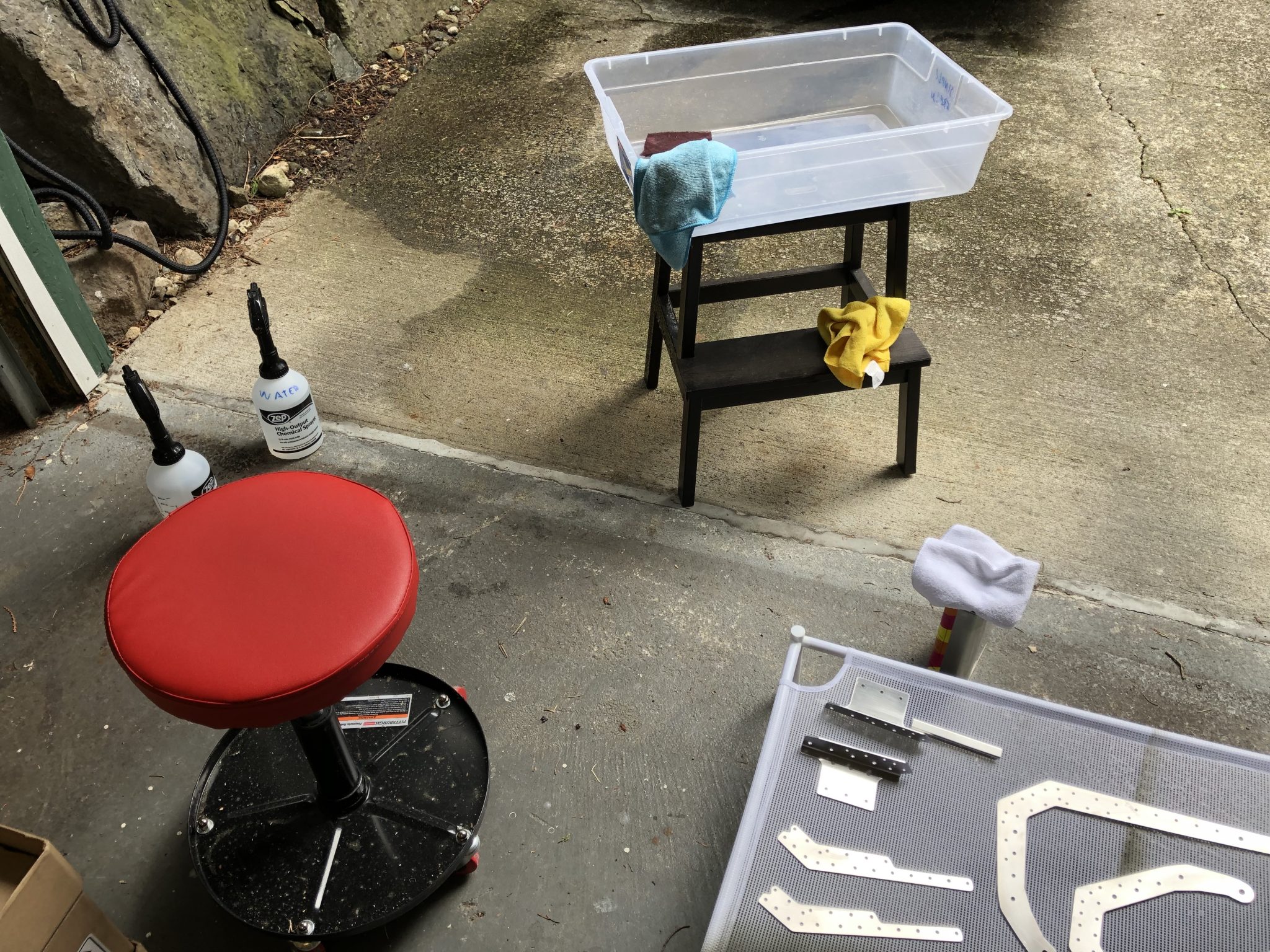
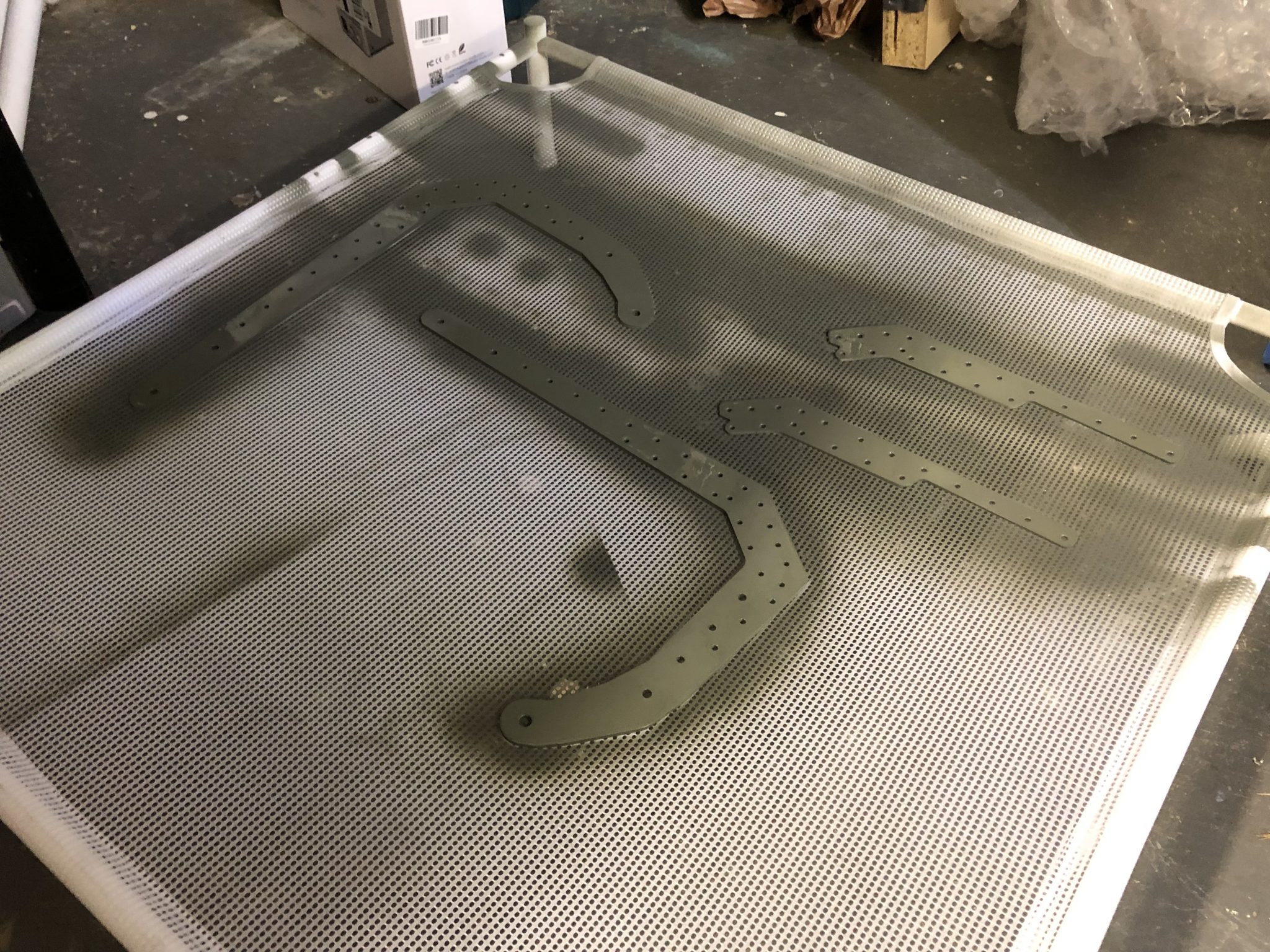
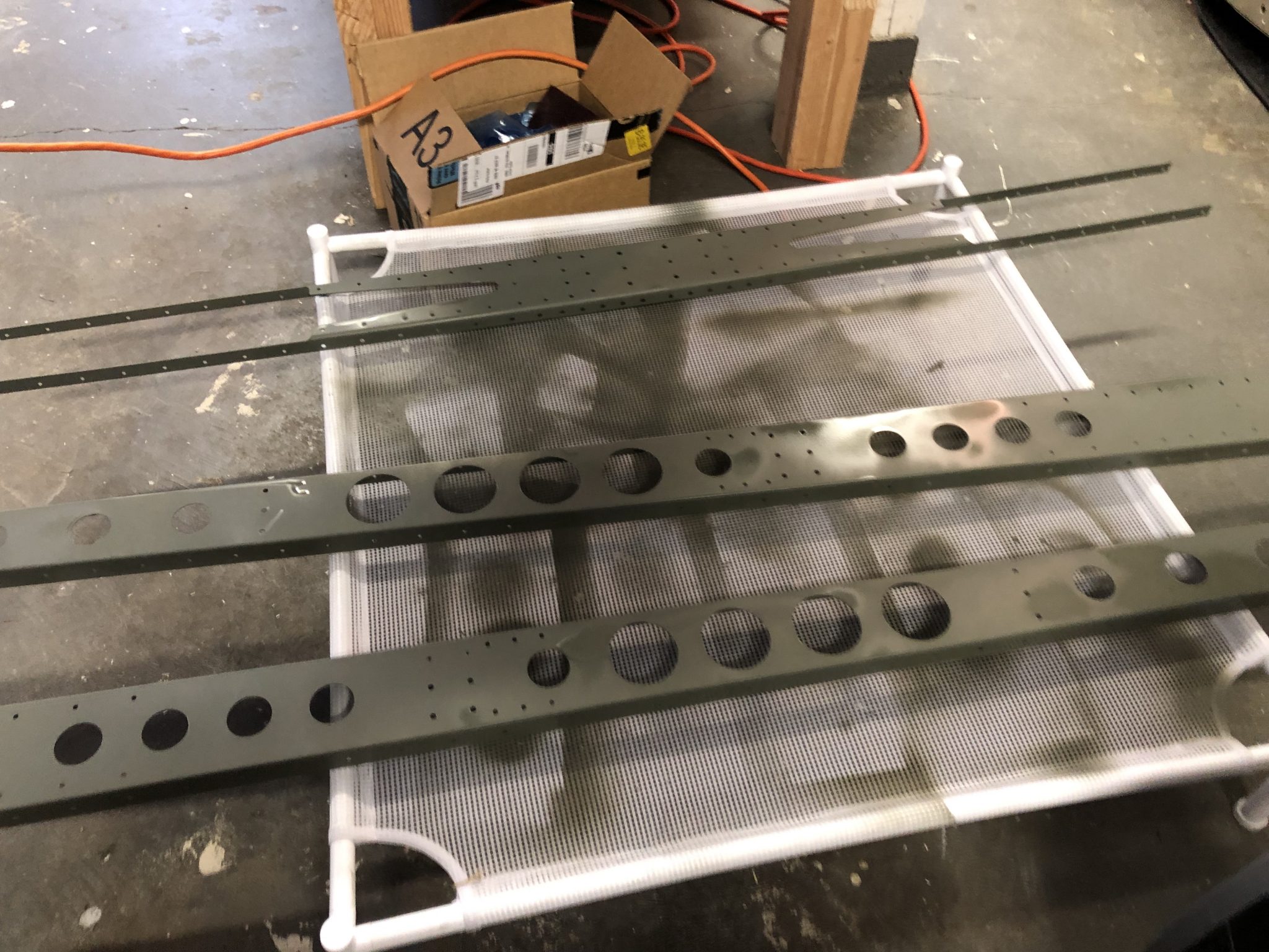
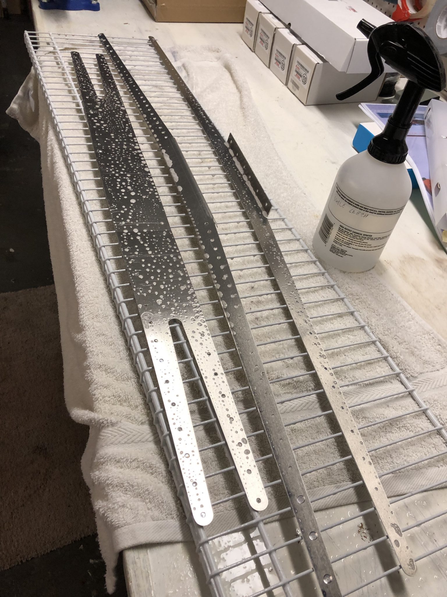
So after some researching I had done ahead of time, here’s the process I decided to follow for preparing the parts for priming:
Washing off the cleaning solution with water and drying the parts
Final de-greasing using MEK
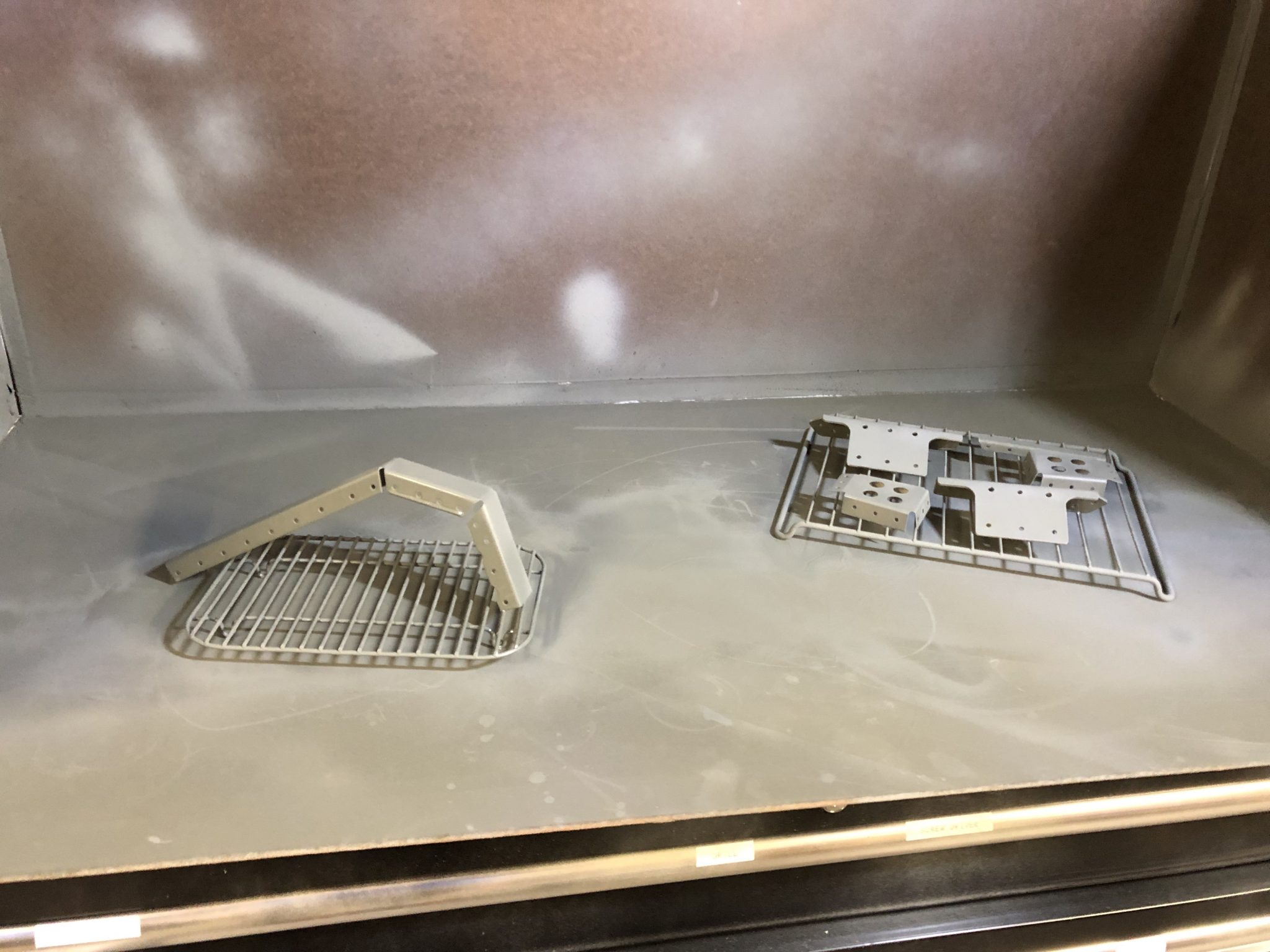
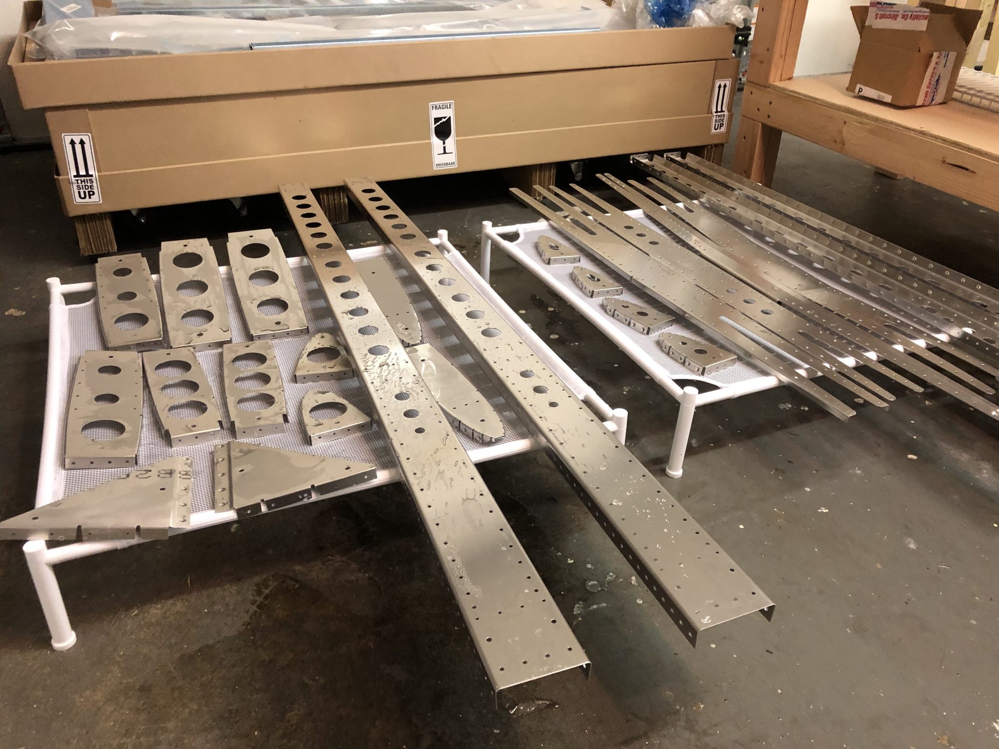
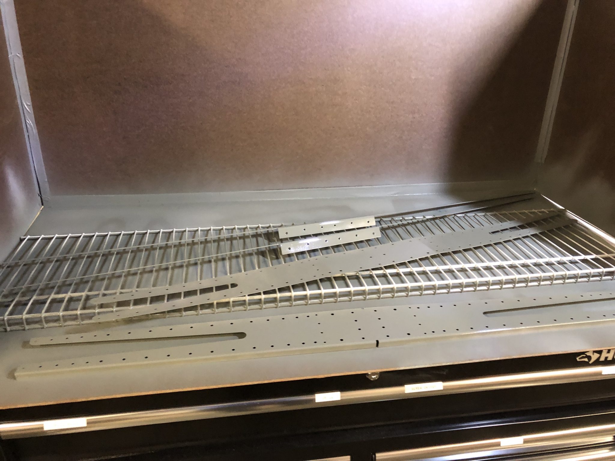
Priming
After all that was done, it was time for priming, which in on itself is a whole big topic with different opinions the more people you ask. I’ve decided to prime the mating surfaces and while at first I was thinking of using NAPA 7220, ended up using Rustoleum Self Etching Primer after I saw that Matthew seems to have good results with it and it’s easier to find in the local hardware store.
Riveting
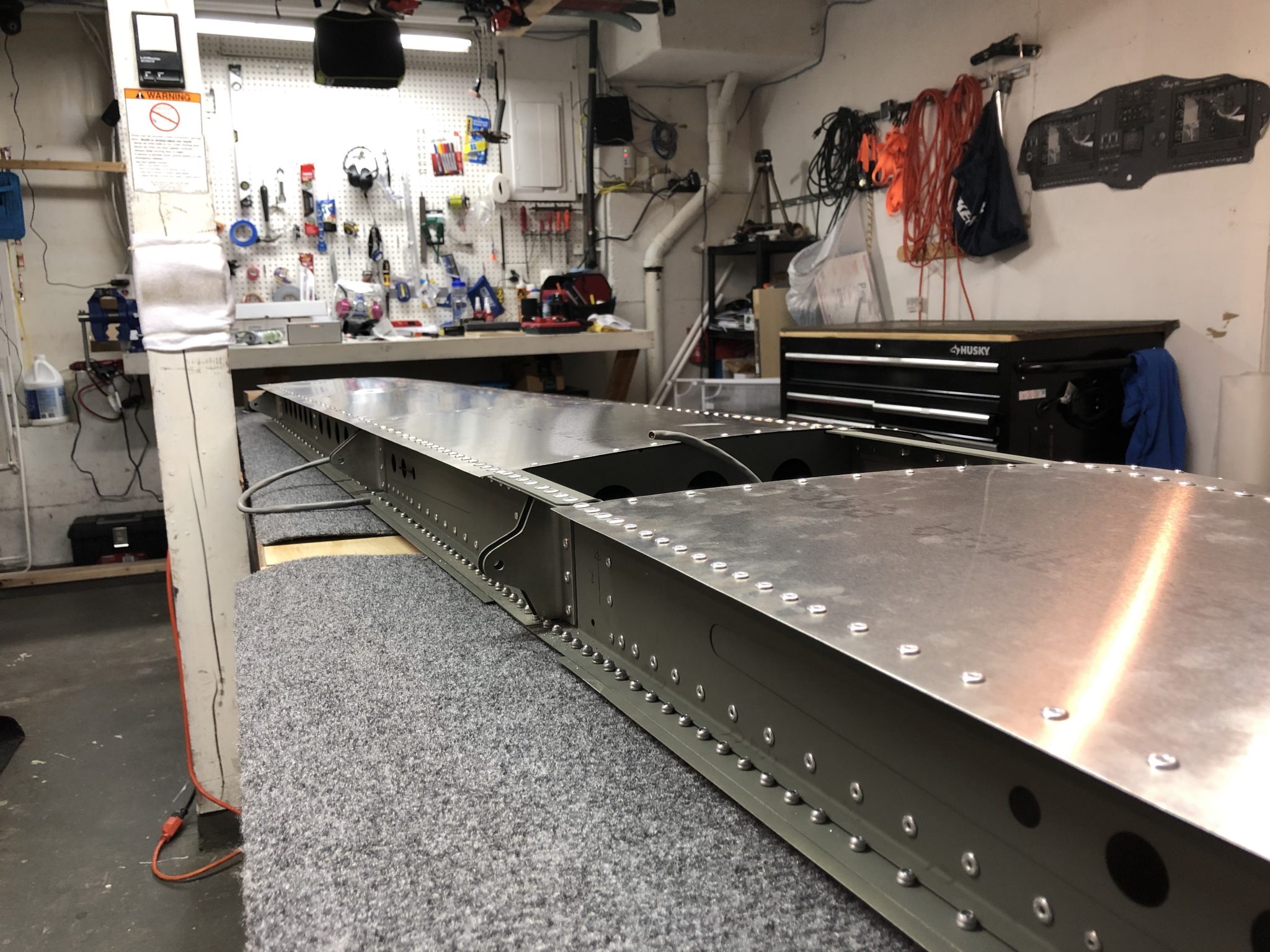
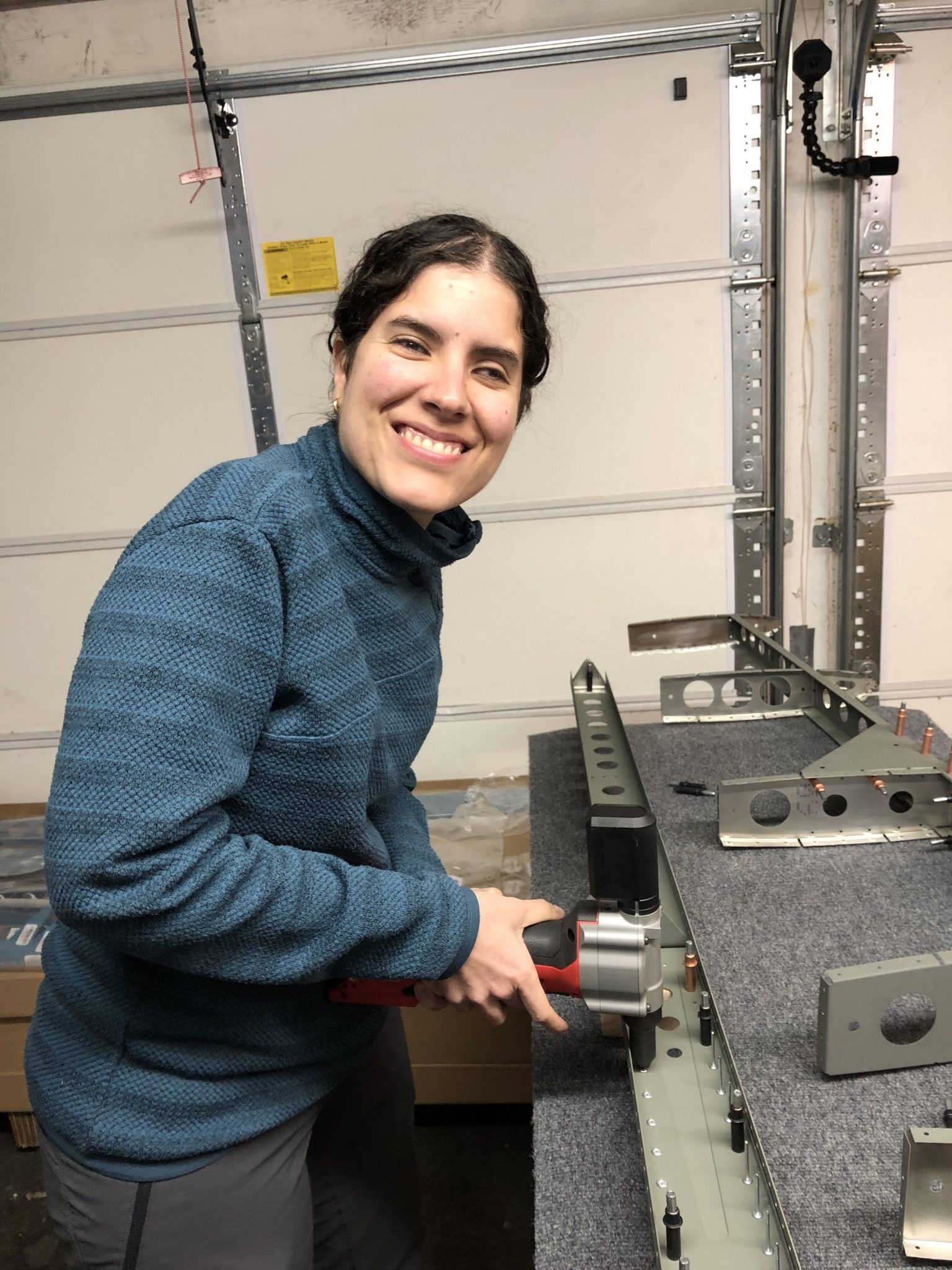
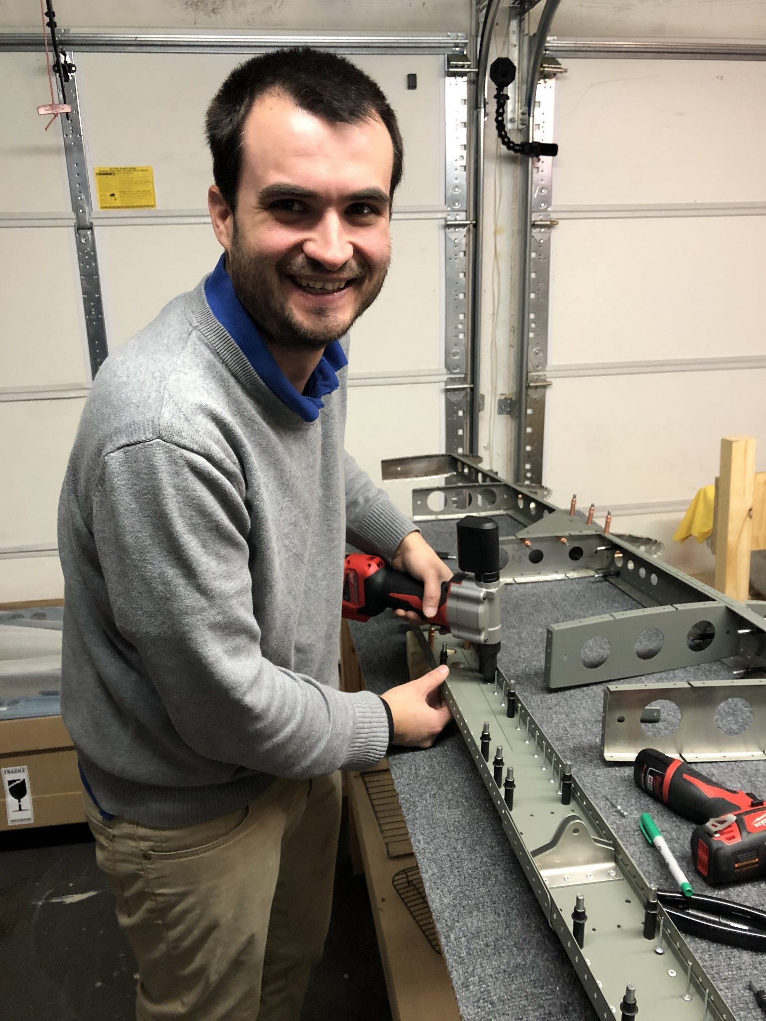
Since my kit was shipped out before the newer revision for the Empennage kit was finished, the printed copy only had the basic CAD drawings, but no instructions, so it’s a matter of combining the larger print outs with the instructions using my small laptop.
Also seen above is the Rivet Gun I’m using – it’s the Milwaukee M12 Rivet gun, which fits in nicely with all my other tools and allows me to build the airplane without the need for a noisy compressor.
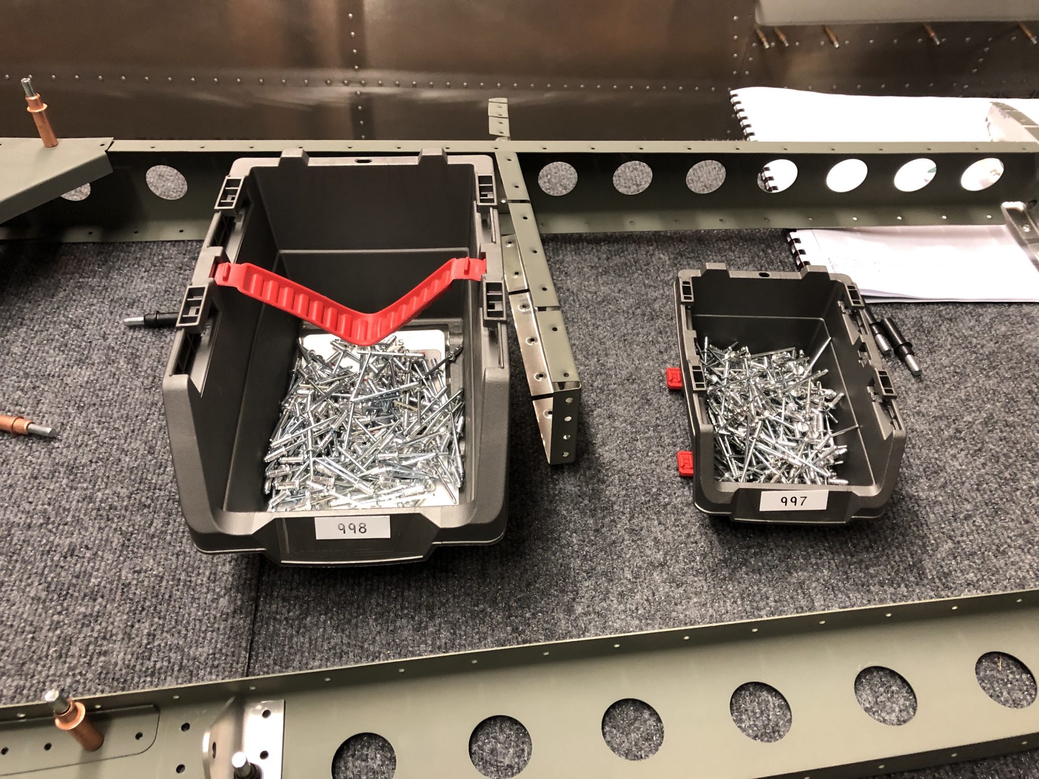
After I put together everything with Clecos it was time to pull rivets.
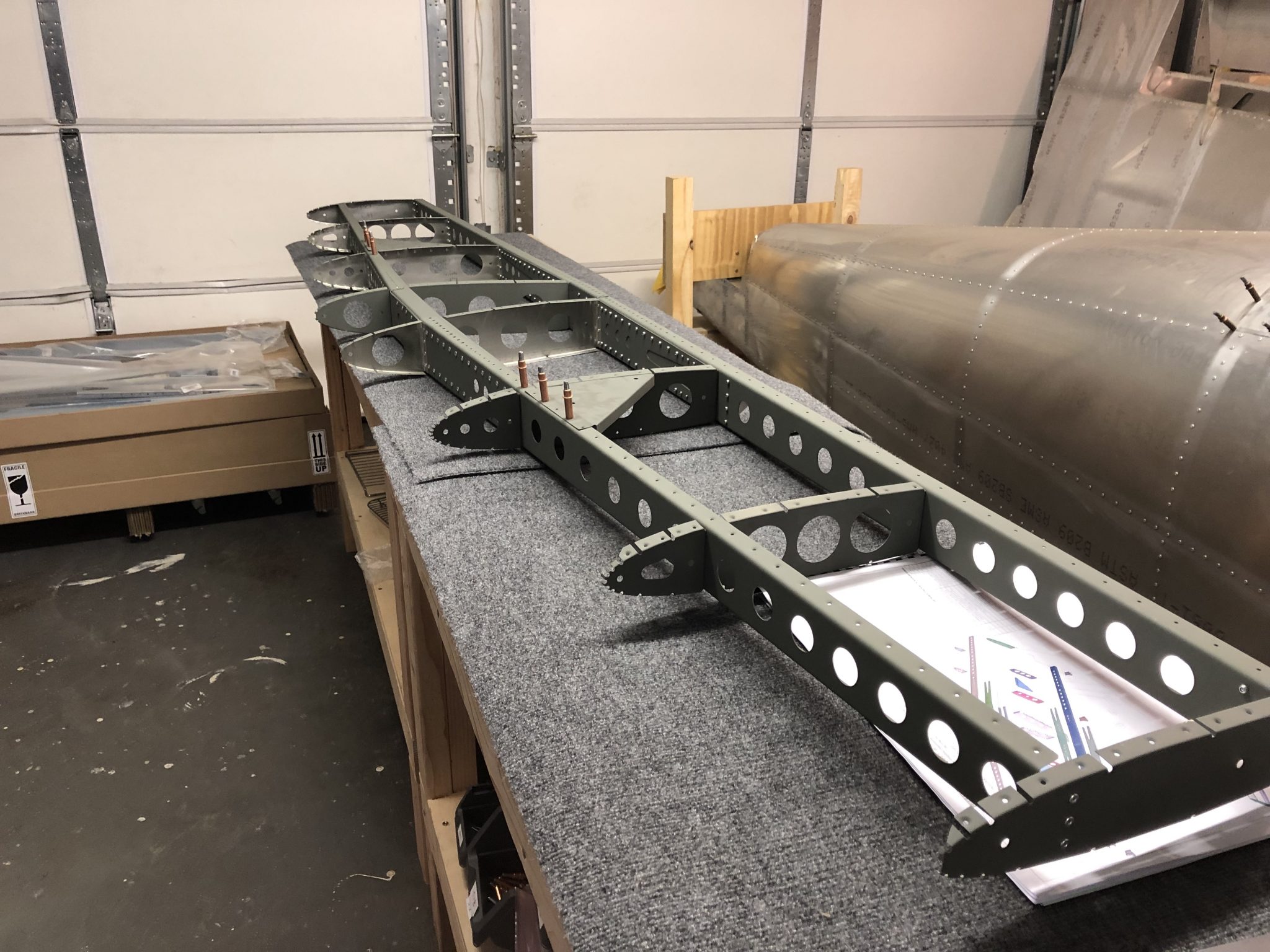
And here’s the riveted structure (minus the skin) of the Horizontal Stabilizer:
I’m also trying to record my progress with some timelapses, so here it goes:
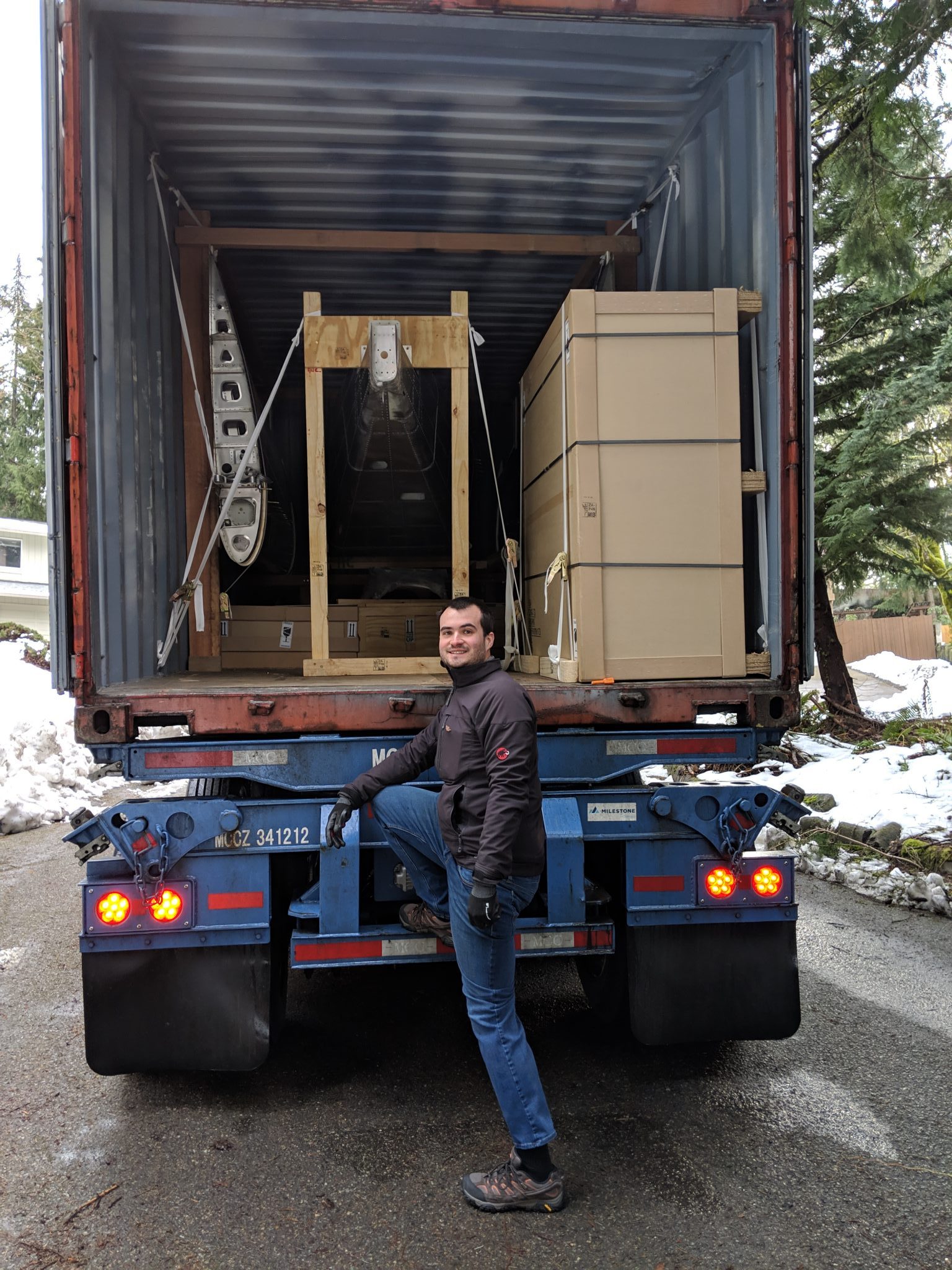
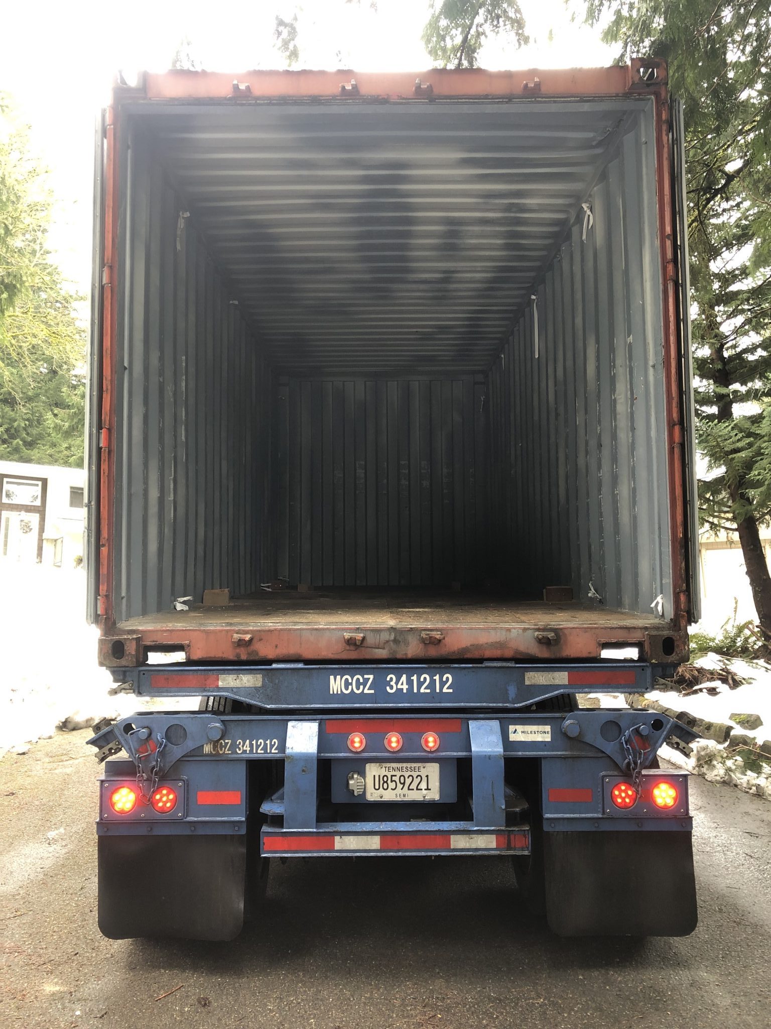
My Sling TSi airplane kit has finally made its way to my garage and arrived yesterday from The Airplane Factory in South Africa. Since I ordered the entire kit in one go as a quick build, it was shipped in one large 20 foot container directly to my house. The container arrived about two weeks ago in the port, but then the Seattle Snowpocalypse happened and we had the heaviest snow in February for over 70 years. The Seattle area is very hilly and so the sudden large amounts of snow and the hills made for impossible driving conditions and so while I couldn’t get a truck to deliver the airplane, instead we went skiing on our road sometime last week since our hill has a pretty steep incline.
Luckily it stopped snowing by Tuesday and warmed a bit and the City managed to start plowing neighborhoods and we could drive again by Thursday, so I called the Freight company and told them they can now give it a shot to deliver and the scheduled the delivery for Monday, which worked out great.
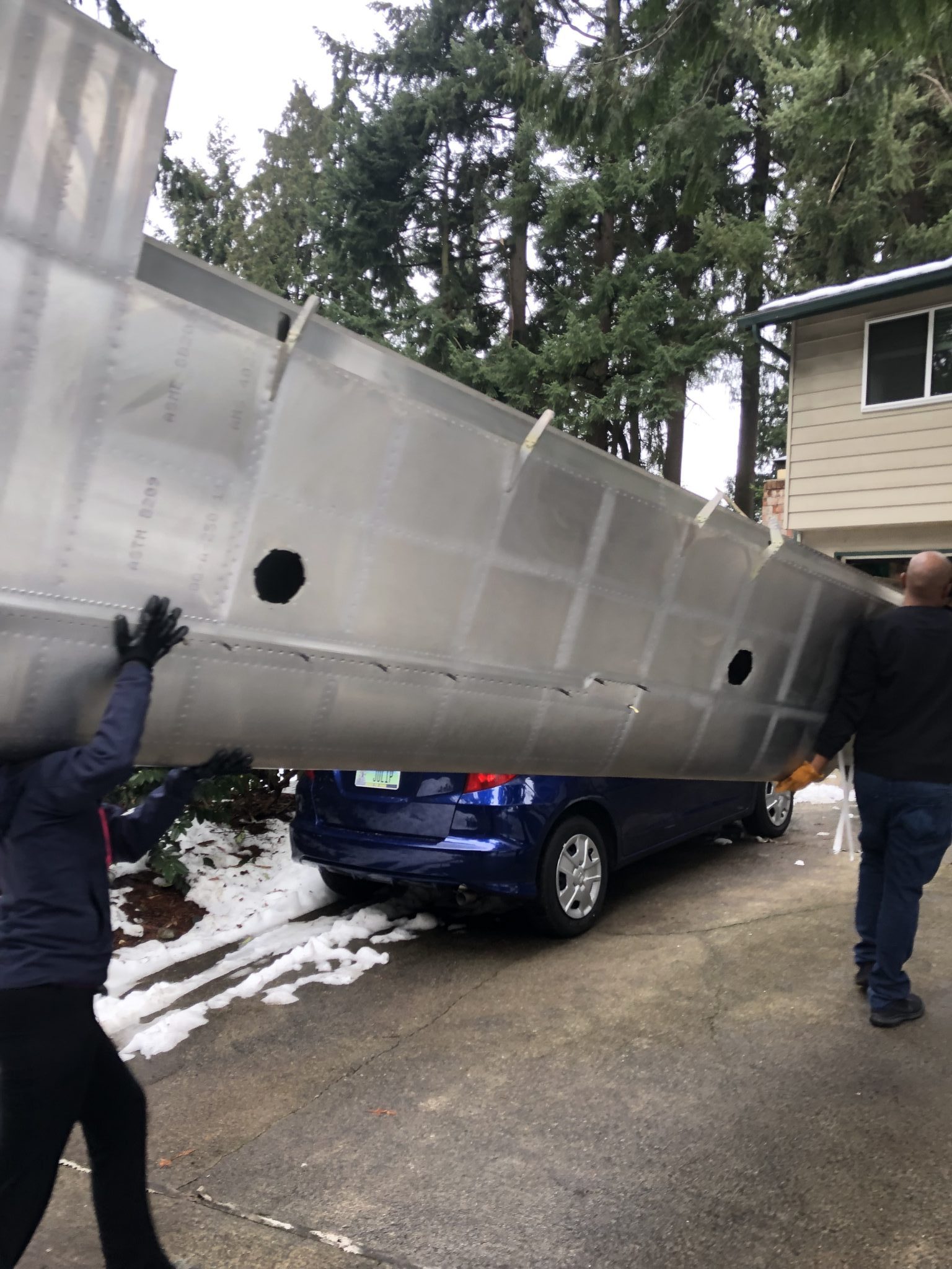
Unloading an airplane from a container
I set up my GoPro to try to capture the unloading process, it worked out fairly well to capture everything, so here it goes:
If this wasn’t enough, then here’s the complete story:
The Truck with the 20 foot container arrived just as my friends, who graciously were on standby the past two weeks to help, were arriving to help me unload and we went to work. The first order of business was to figure out the order to unload the container.
After taking out the big box with the Finishing kit on the side, we juggled around a bit to see if we could take the boxes on the bottom out, but they were blocked by the Fuselage Tail support, so we figured that we should take out the Fuselage next. The wood that the Factory used to build the framing is of some impressive quality and the heavy screws driven into them were very tight, so it took some loosening by hand before even my impact driver could undo the screws, so I grabbed my trusty Milwaukee M12 Hackzall and made due process so we could get on with unloading and then undo the rest of the structure later. That and heavy use of my Utility Knife to cut through the many support straps that held down the structure.
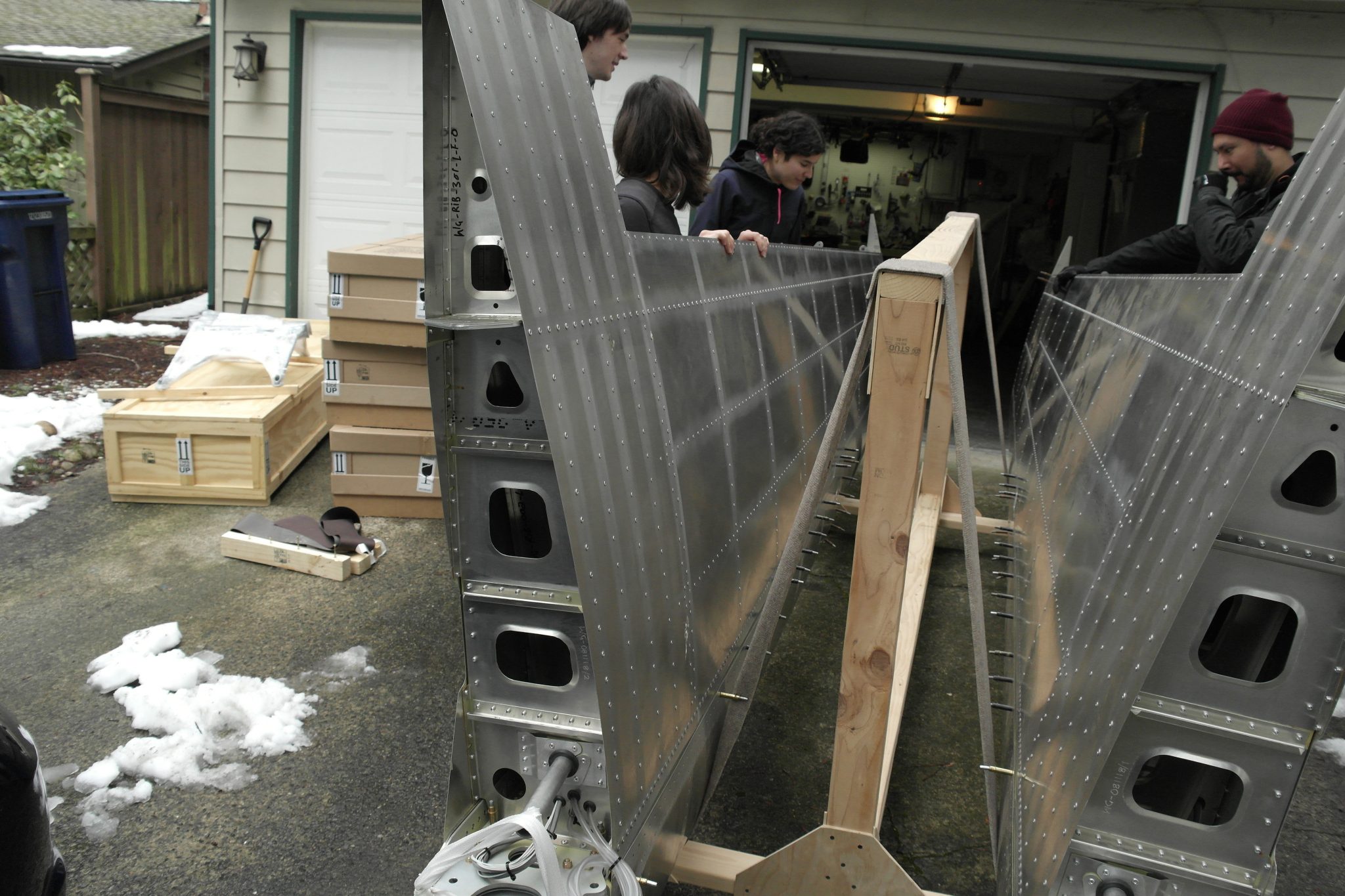
After we got the Fuselage out, it was time for the boxes that were stored under the Fuselage, followed by the Wings.
After all that was said and done, we took down the rest of the wood framing in the container so the container was truly empty in the end:
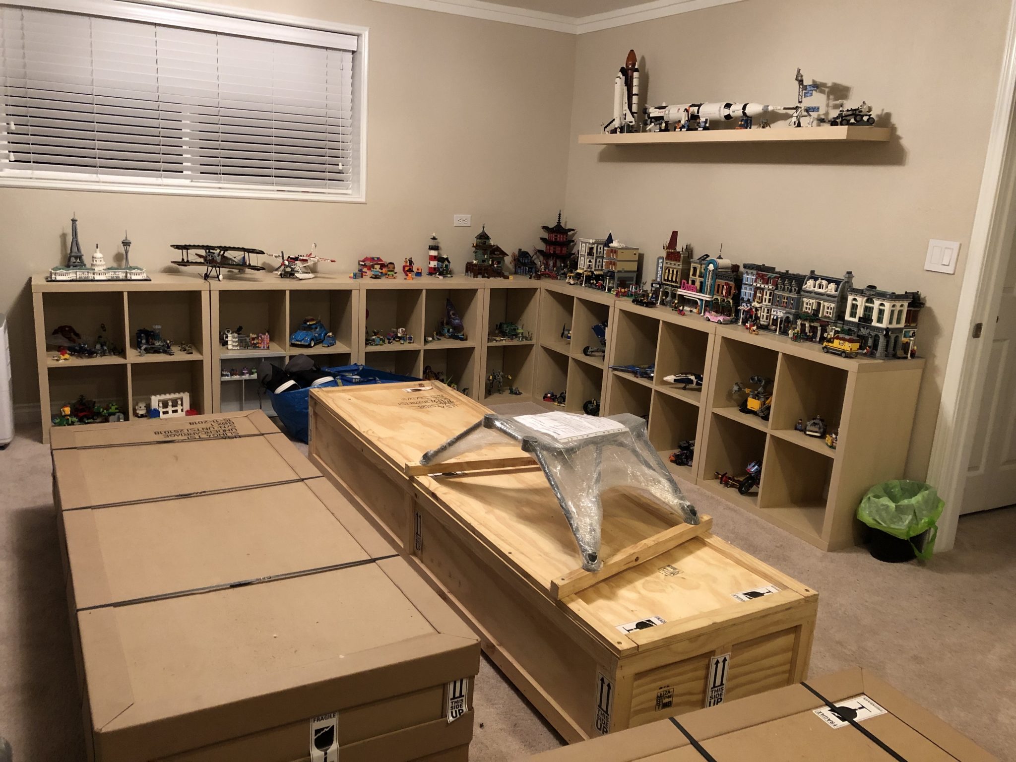
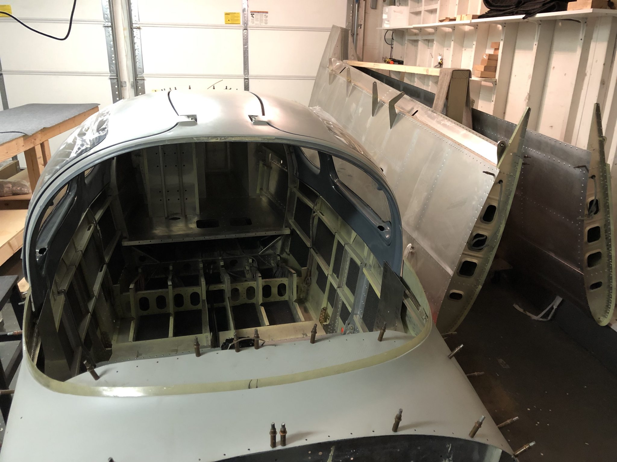
We moved the boxes into our basement multi function room, next to our LEGO collection – building your own airplane is kind of like LEGO right?
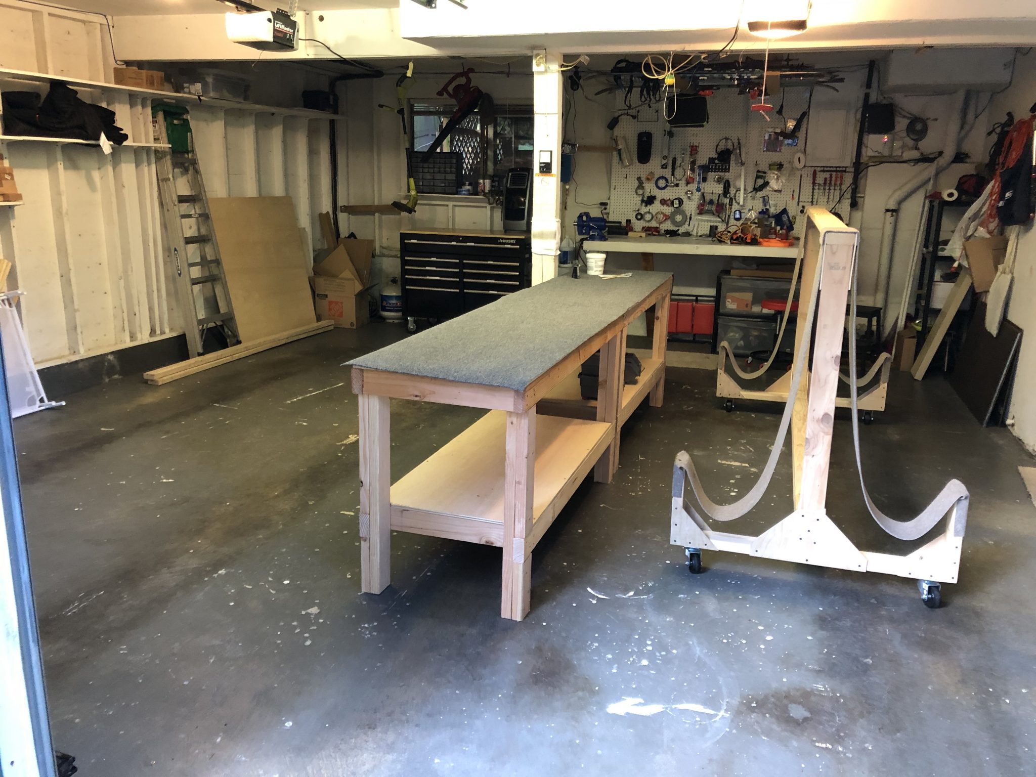
And the Fuselage and Wings found their home in the Garage on one side, leaving me with the other side as work space, plus I can easily move the wings around since I have wheels on the wing rack.
Cleaning up and taking inventory
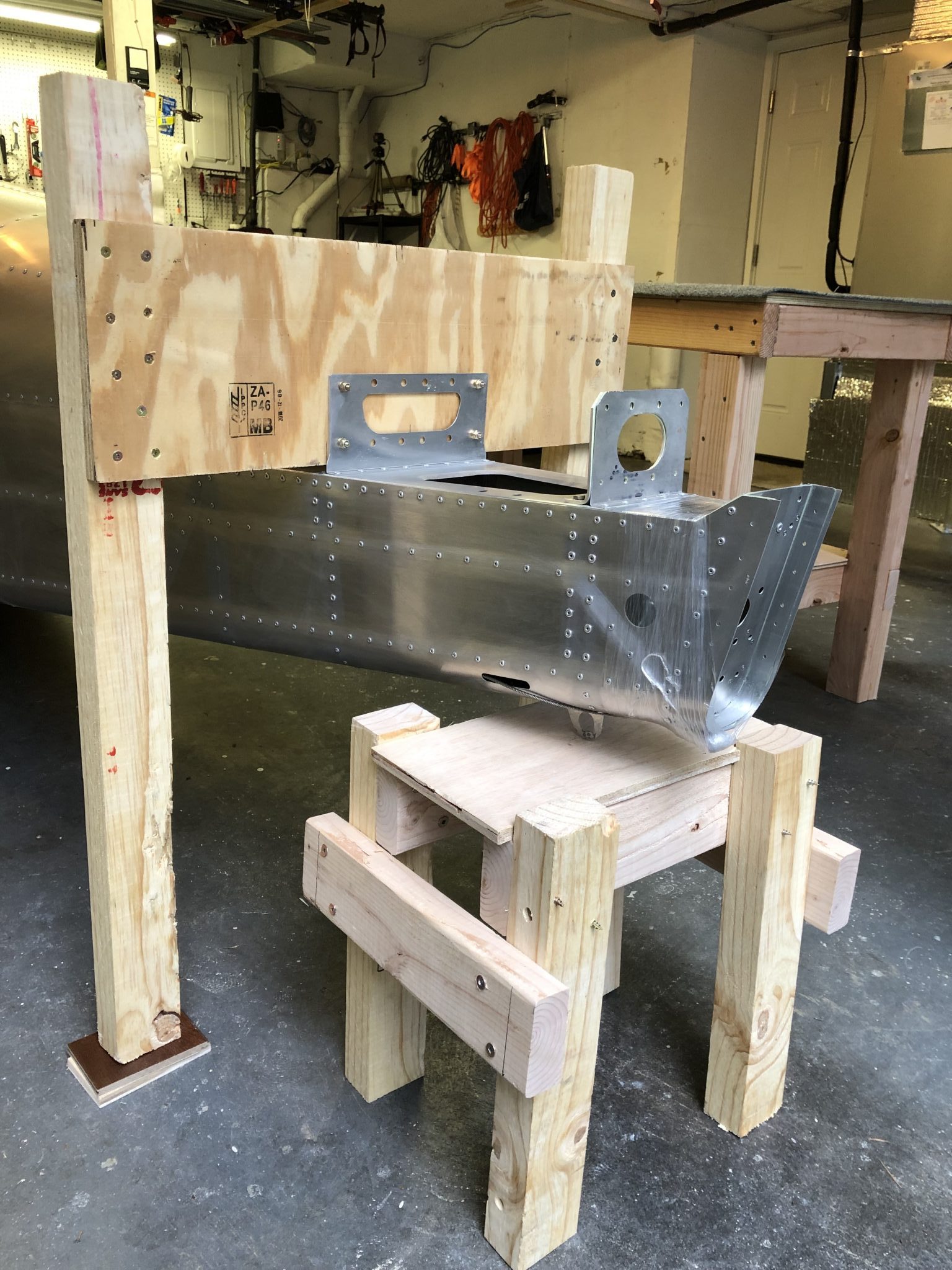
I felt like the tail should have some extra support, so I quickly built a small stool for the tail to rest on, in addition to the existing framing that it came in, here is a quick timelapse of me cleaning up the workshop and building the stool:
Stool for the Tail to rest on:
After that was done, I asked Juliana to come down to the Garage as I was pretending to fly the airplane as any reasonable person with a new toy in their garage would do:
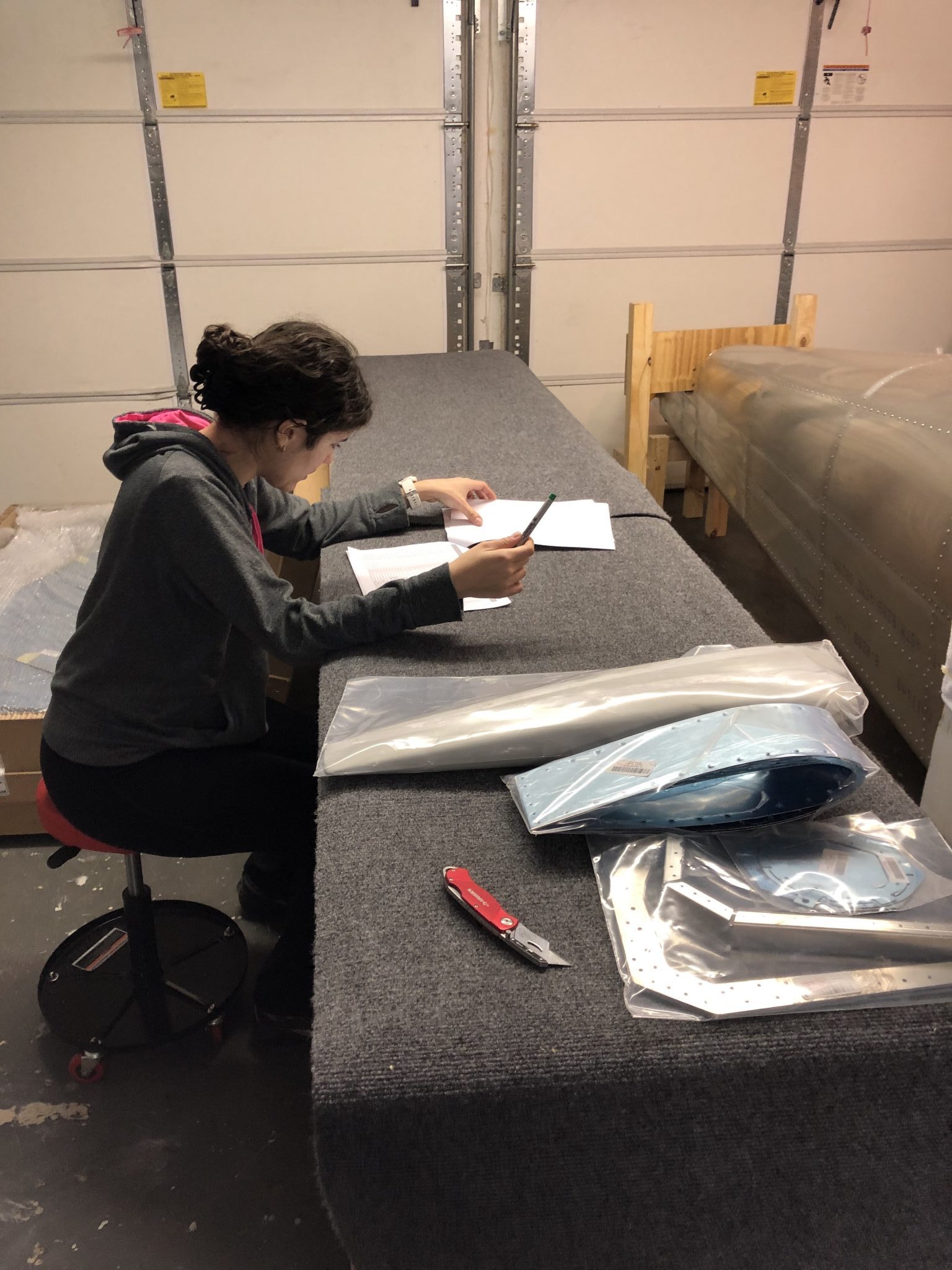
And then we opened the Empennage box and started taking inventory so I can stop building wooden tables and stools and start building an airplane:
This should hopefully be the last “waiting for the kit” post. The container with the kit has arrived at the port a couple of days ago. The logistics company is working through arranging the truck to bring the container to my house to unload. Hopefully I’ll have some good news tomorrow and have a firm date for the delivery this coming week.
The garage is ready for delivery and I also picked up a wing stand to store the wings from the flying club I am a part of, as we just installed the wings onto the Cessna 150 airplane we are refurbishing for an upcoming charity raffle to fund college scholarships for kids that survived cancer. The wing stand is from a design by Tony Bingelis and can be found on the EAA website here.
I took a time lapse of the process of installing the wings on the Cessna. It took a little bit of lifting and then a lot of jiggling to get the bolts in place.
I also attended a discussion meeting at our local EAA 84 chapter last week about going to Oshkosh, which was very interesting as I haven’t yet managed to go to Oshkosh myself as I was busy last year finishing up my instrument rating, so I’m hoping this year might be my first. If I go, I will likely fly commercial and then camp there and I’d love to meet some other Sling Builders at the Sling Ding Party hosted by The Airplane Factory and Sling 2 builders Bob & Joan.