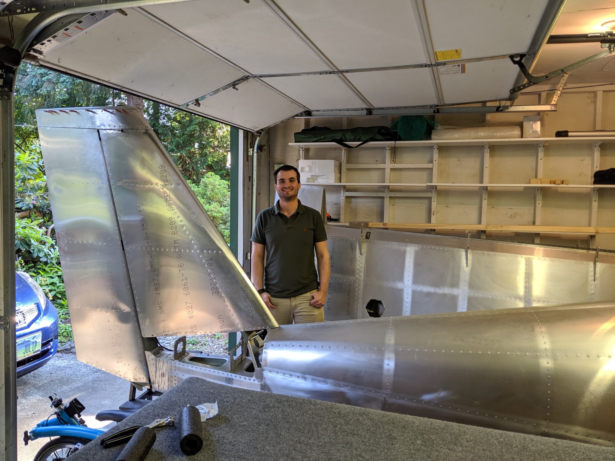
After a couple of weeks of taking some time off active building while life happens and figuring out and planning out some things, I’m back to actively riveting on the airplane.
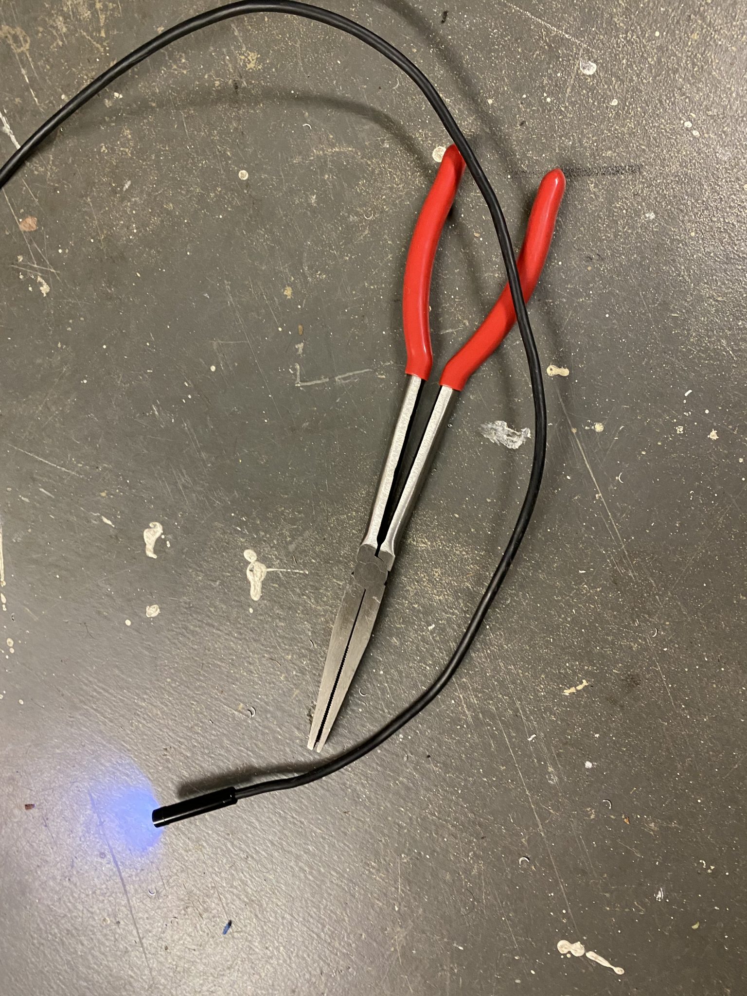
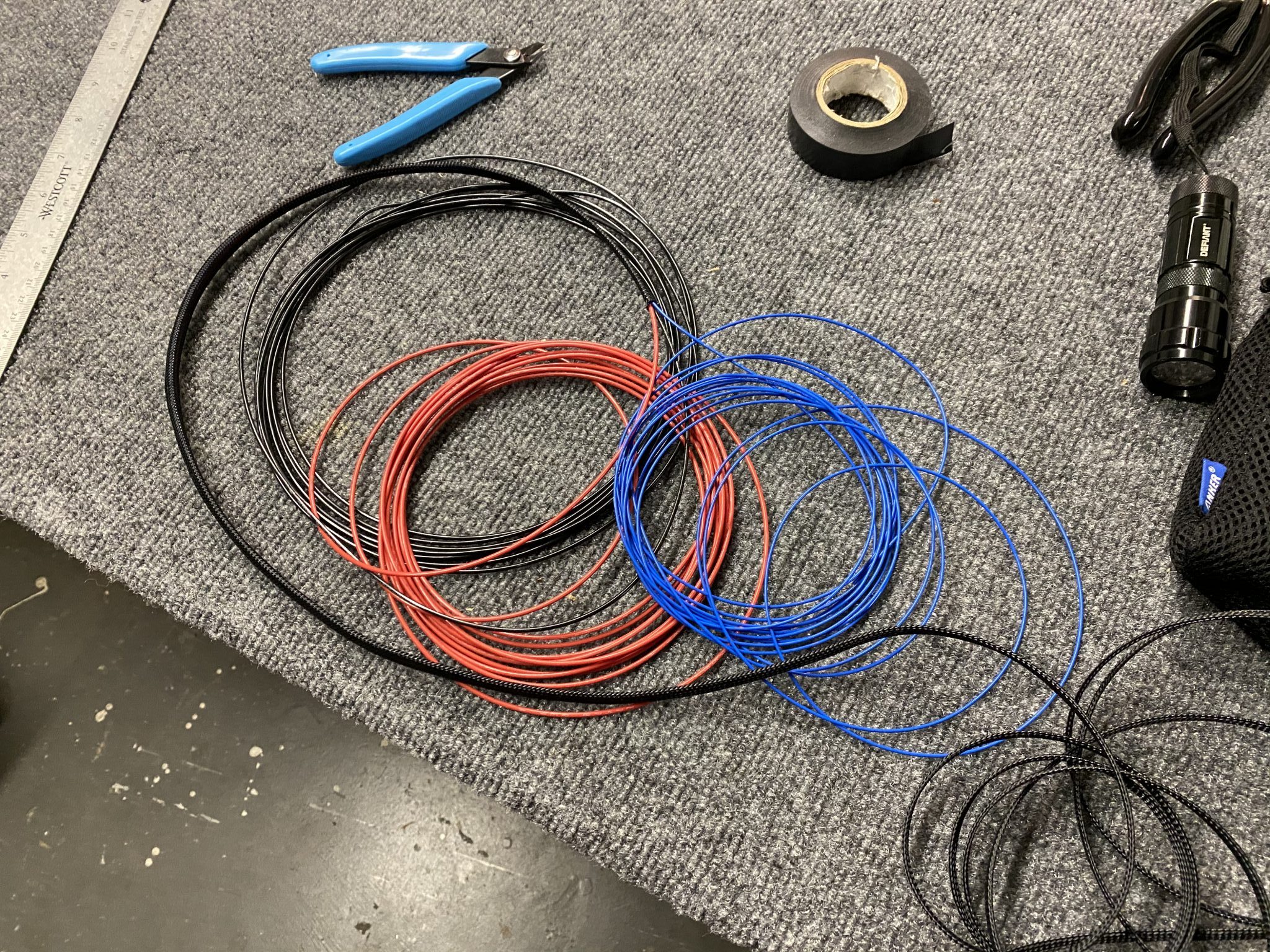
Time to finish the Pitot Tube after having cut the inspection panel hole and running the wiring a few months ago and lots of learnings about new tools, from the wiring, to flaring the tubes and connecting AN fittings.
I’m using the Garmin GAP 26 heated & regulated Pitot Tube (GAP 26-20). This version automatically controls whether the Pitot Tube needs to be heated using a regulator controller that is mounted next to the Pitot Tube and will only apply heat if needed based on outside temperatures.
This basically will allow me to always turn on the Pitot Tube in my panel as part of my standard operating procedures and the regulator will control whether it actually needs to be heated to prevent icing.
The installation instructions for this can be found in the Garmin G3X installation Manual.
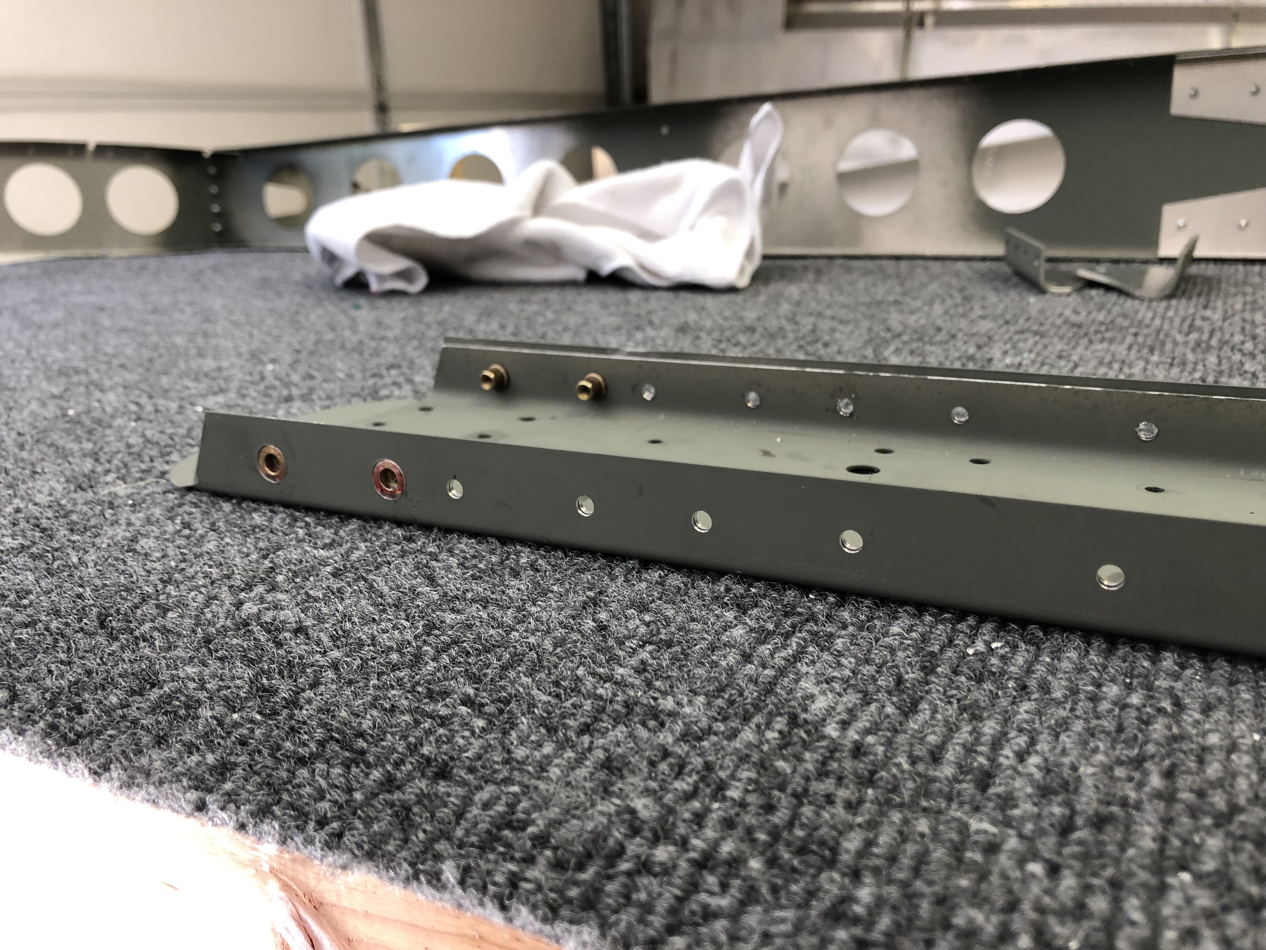
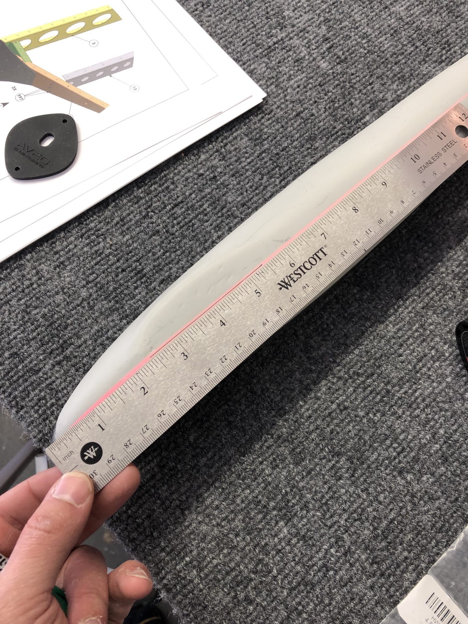
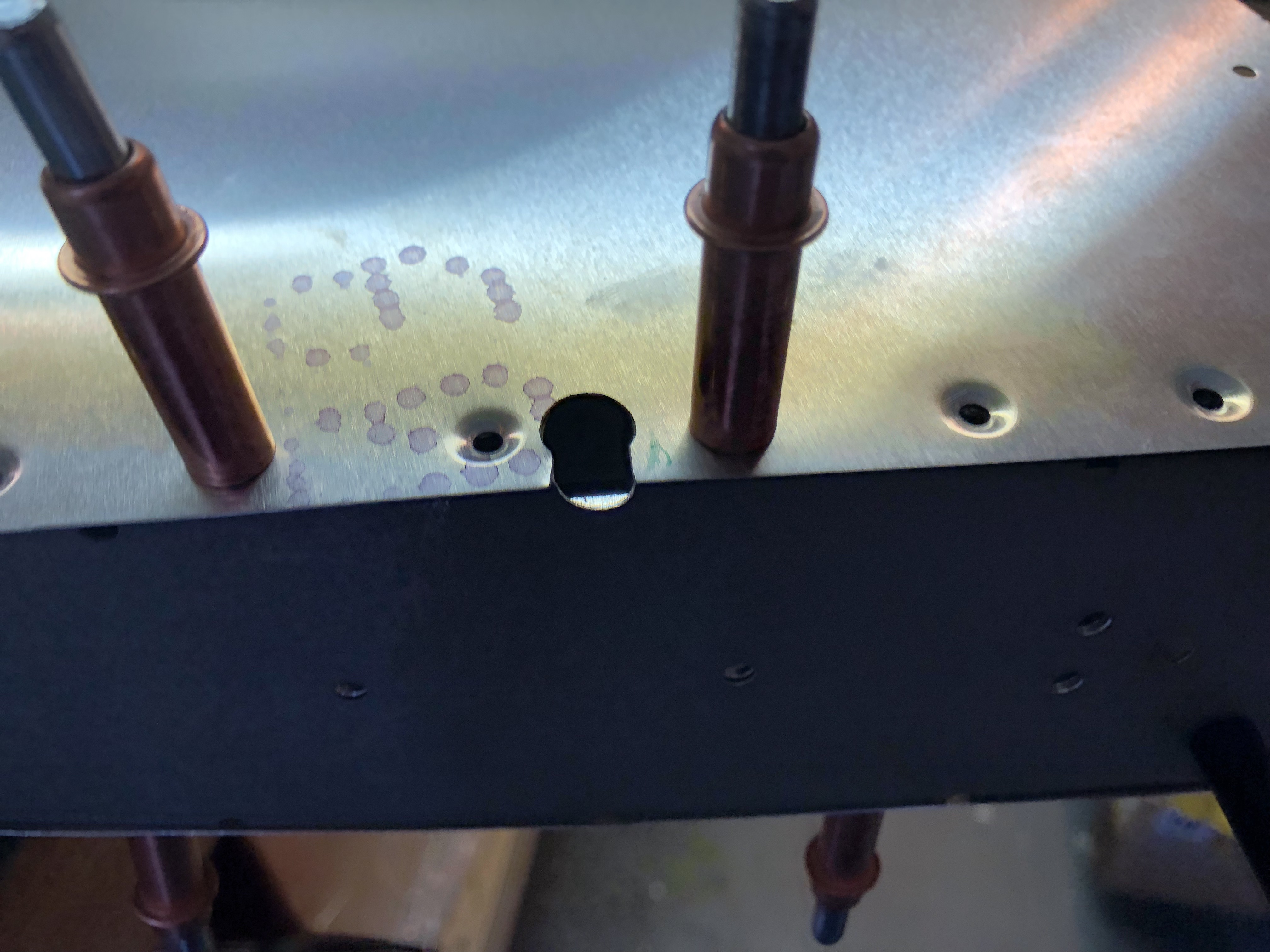
After studying the installation manual to make sure I install it correctly, I measured the tube and had to figure out how far I have to cut it in order to fit.
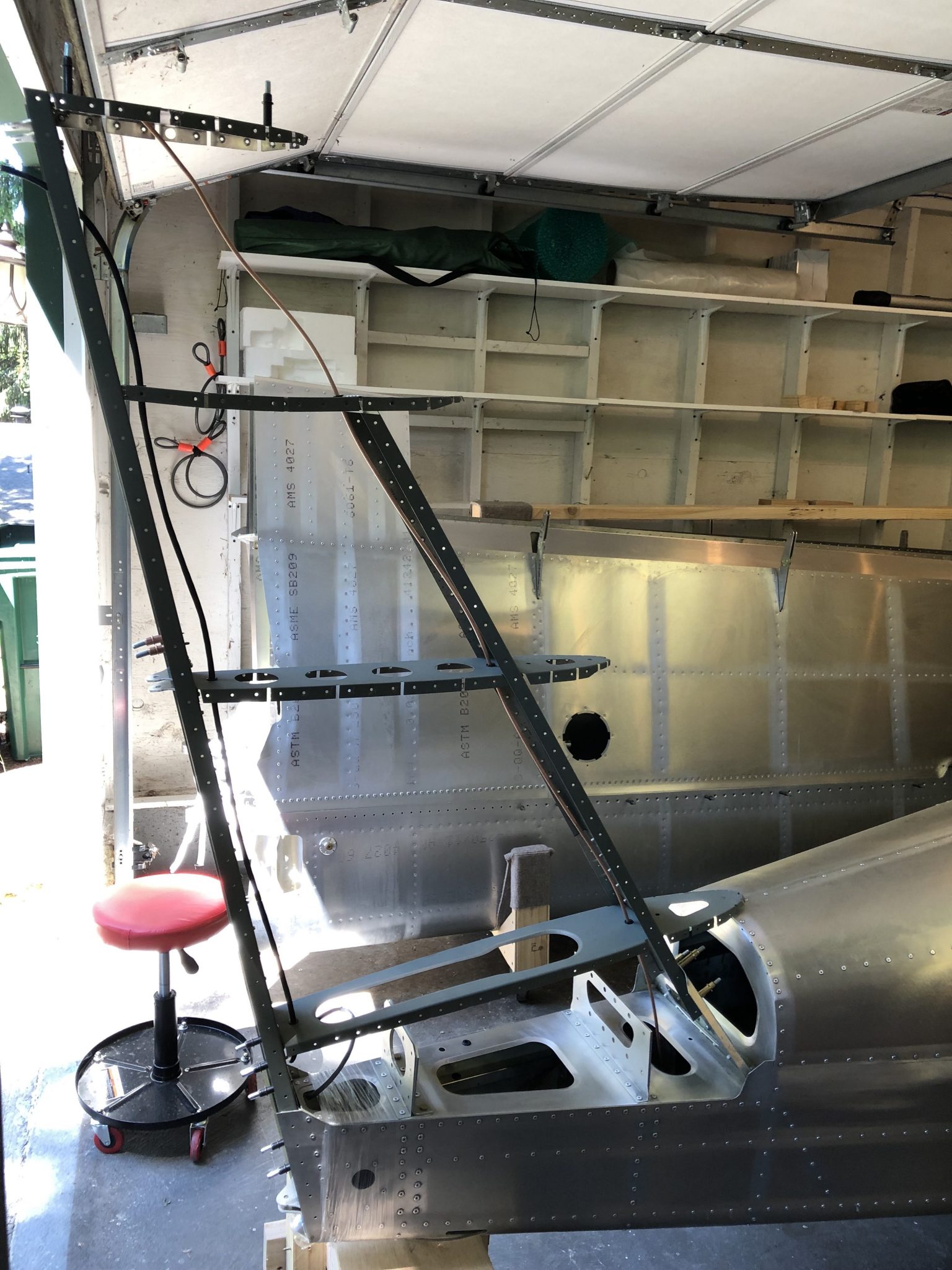
Fitting the Pitot Tube
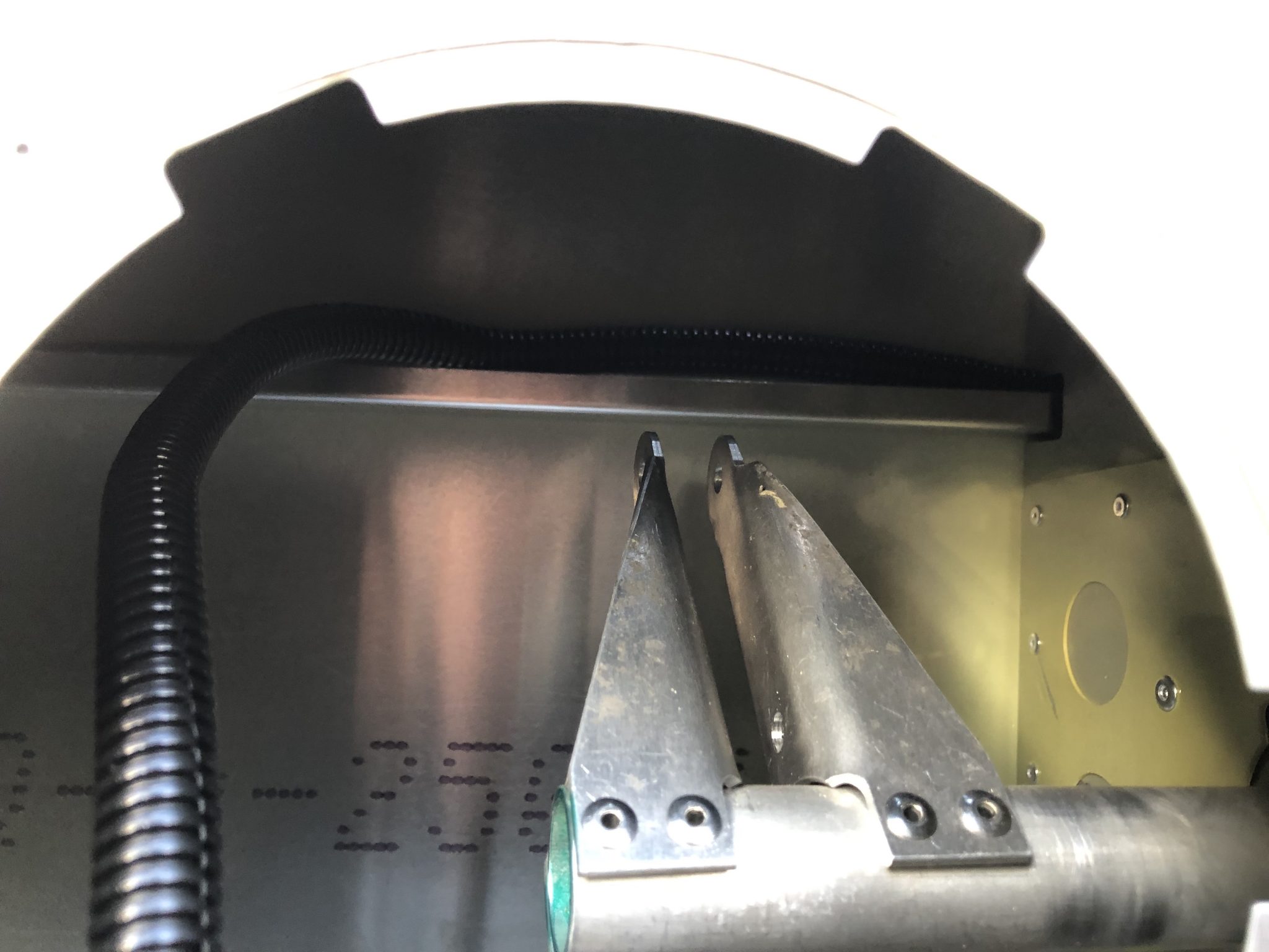
The Pitot and Angle of Attack (AOA) mast are over 12 inches out of the box, and that won’t fit. I made an initial guess and cut a bit shorter, but I was still too long so I made a series of shortenings and test attaching the fittings until I had it dialed in.

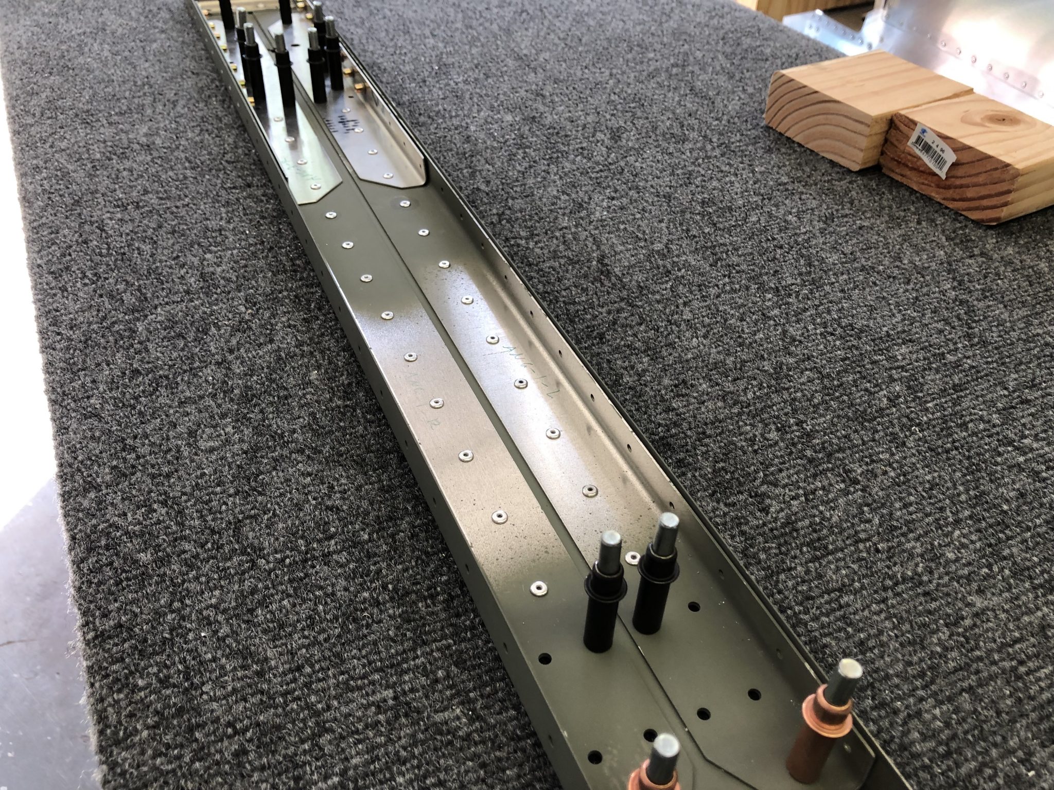
In the end, I had the masts cut down to right around 8 1/2 inches. The Garmin manual says to keep a minimum of 8 inches between the probe and transition to non-metalic tubing, so I had a little bit of margin.
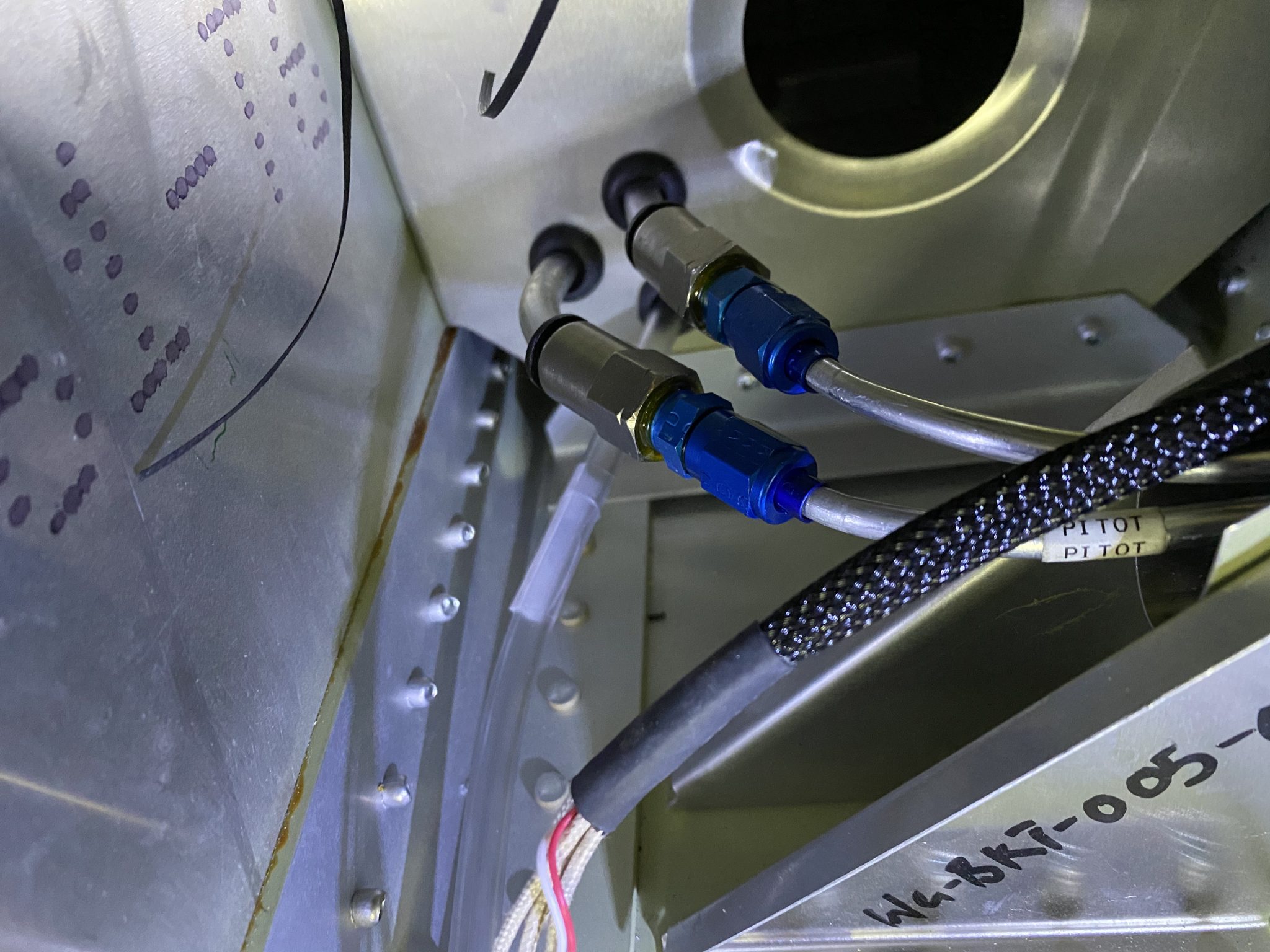
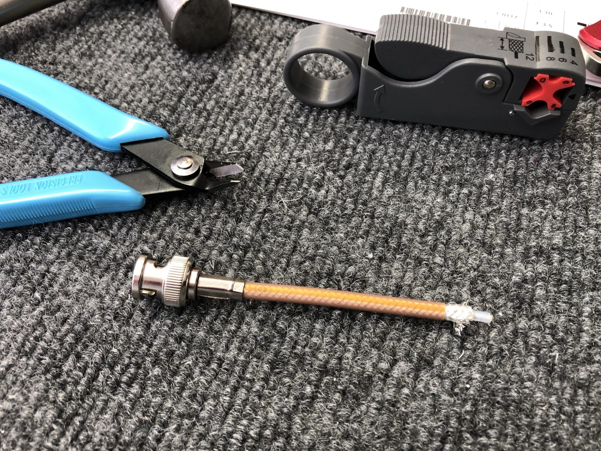
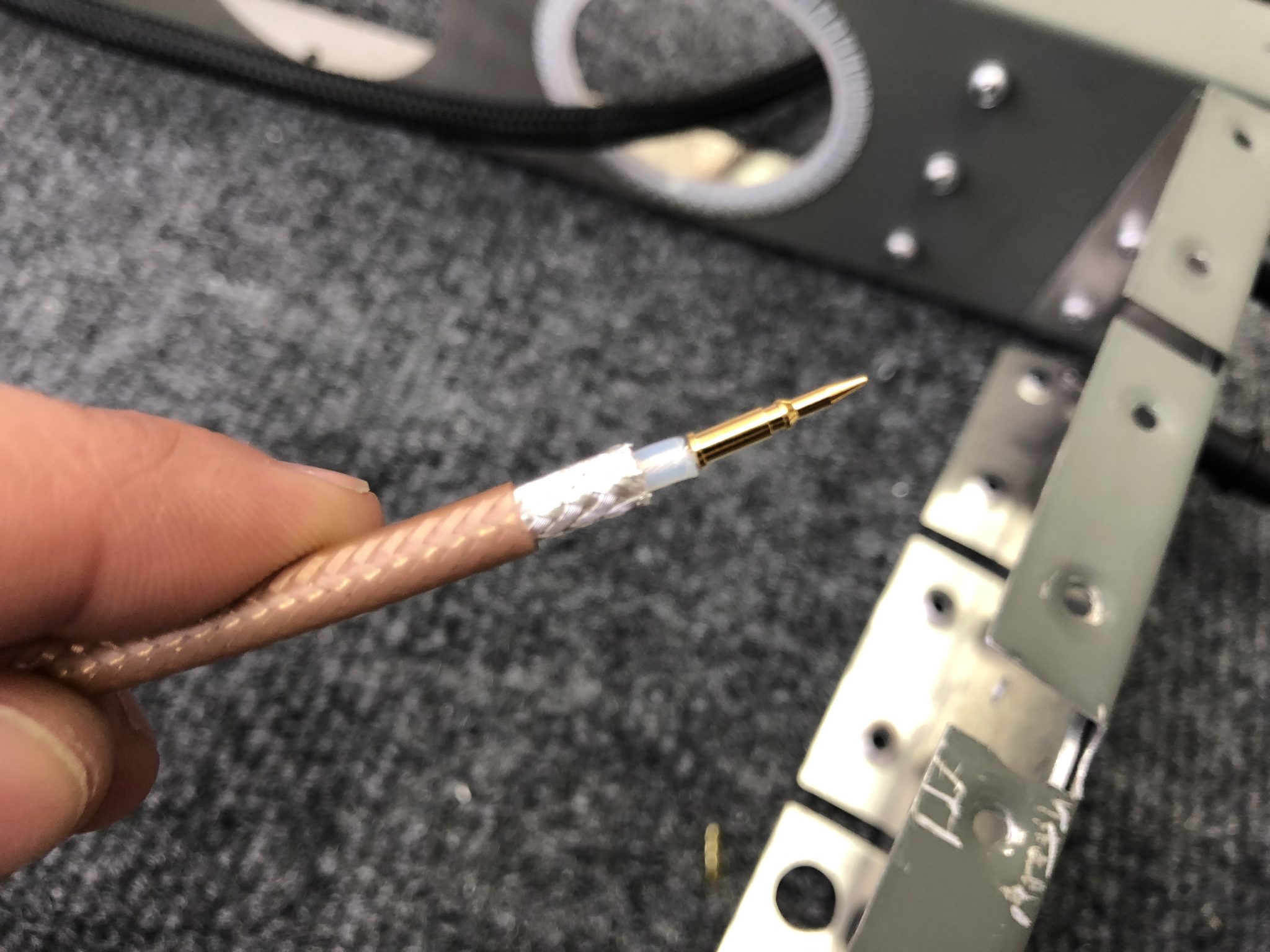
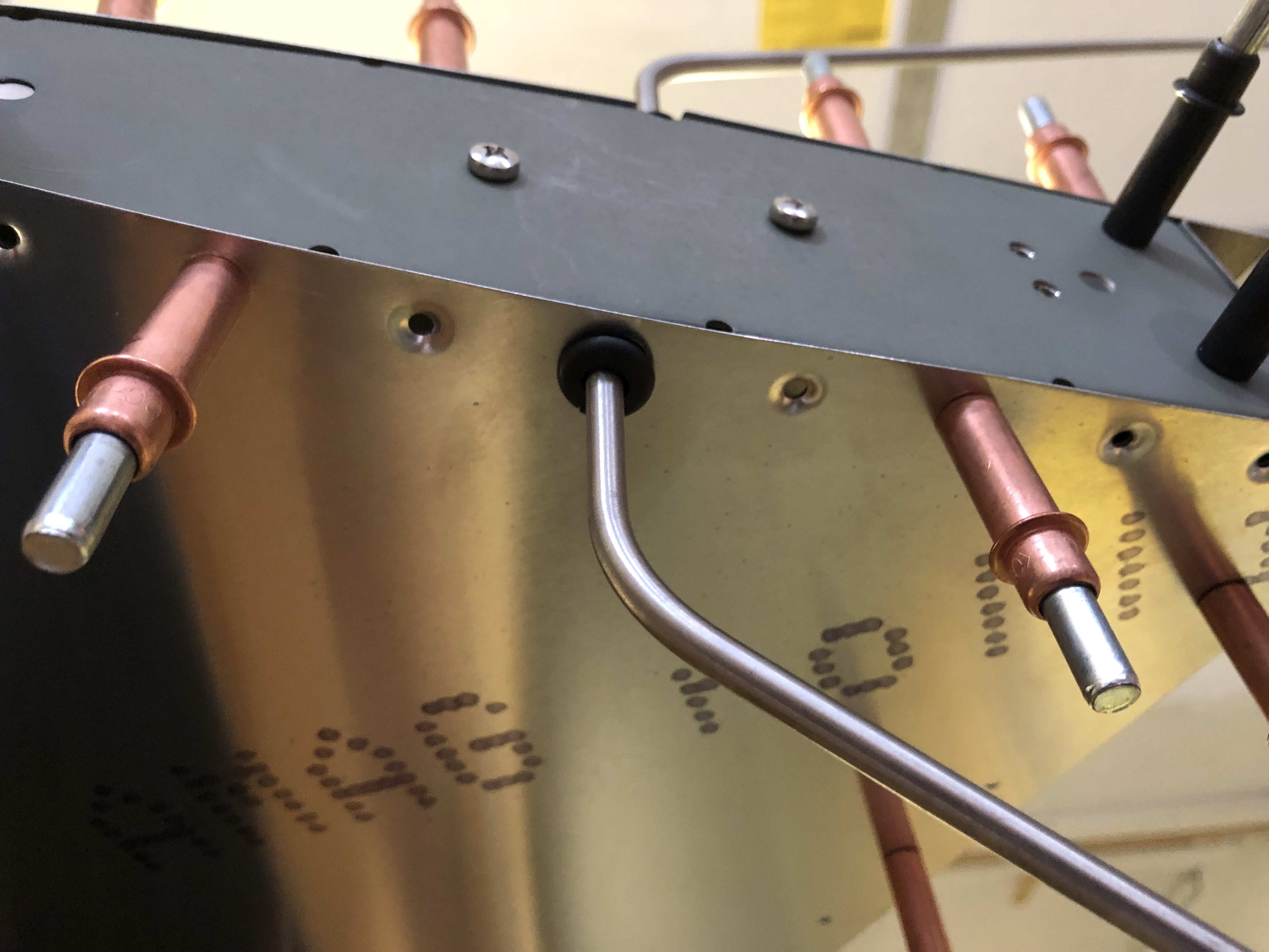
Time for flaring the tubes. The AN fittings use a 37 degree flare, so I got a Rigid 377 flaring tool and a metal tubing cutter to cut the tube. Before doing this on the real Pitot Tube, I made some test flares on a spare tube I bought from Aircraft Spruce.
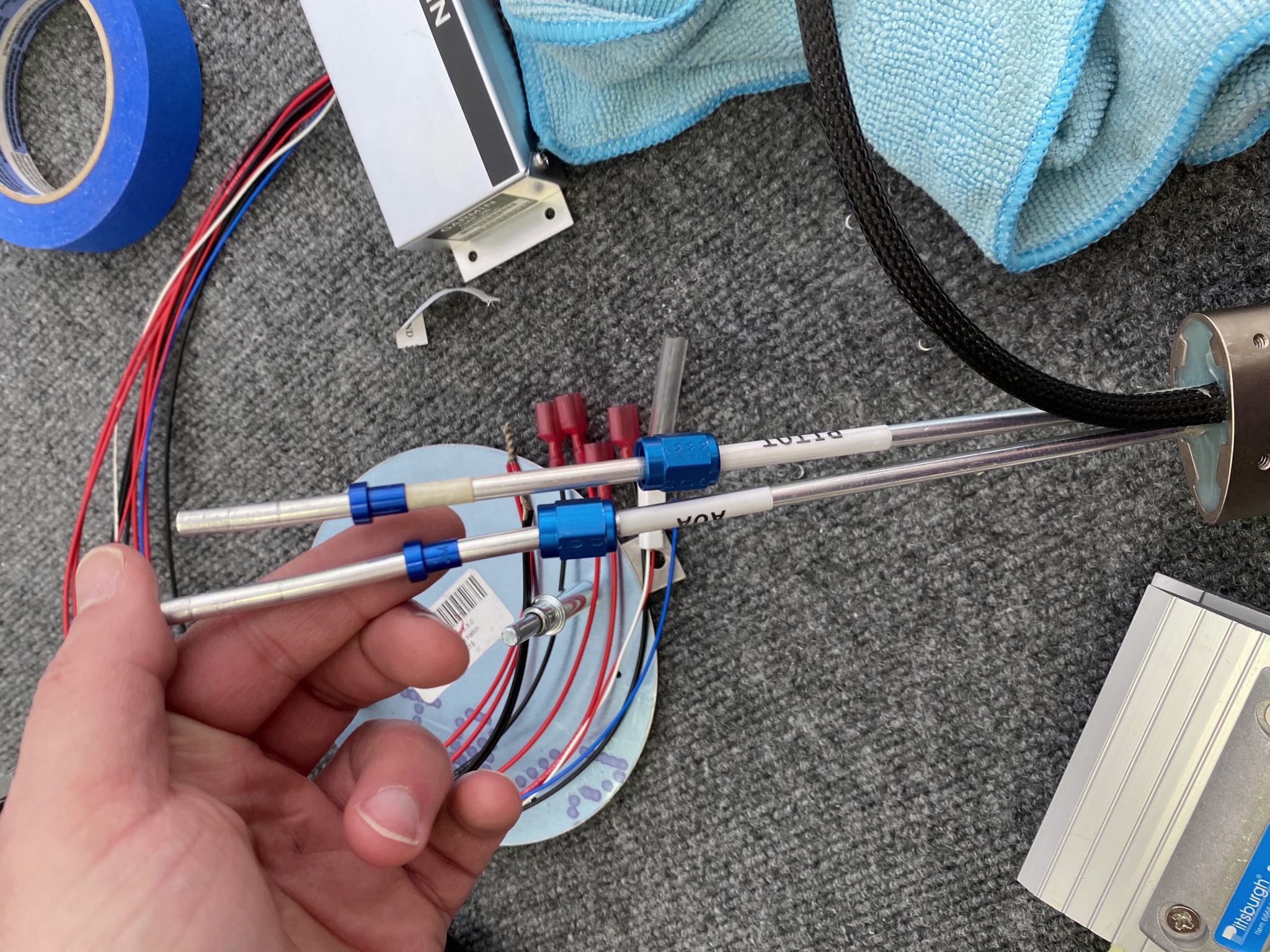
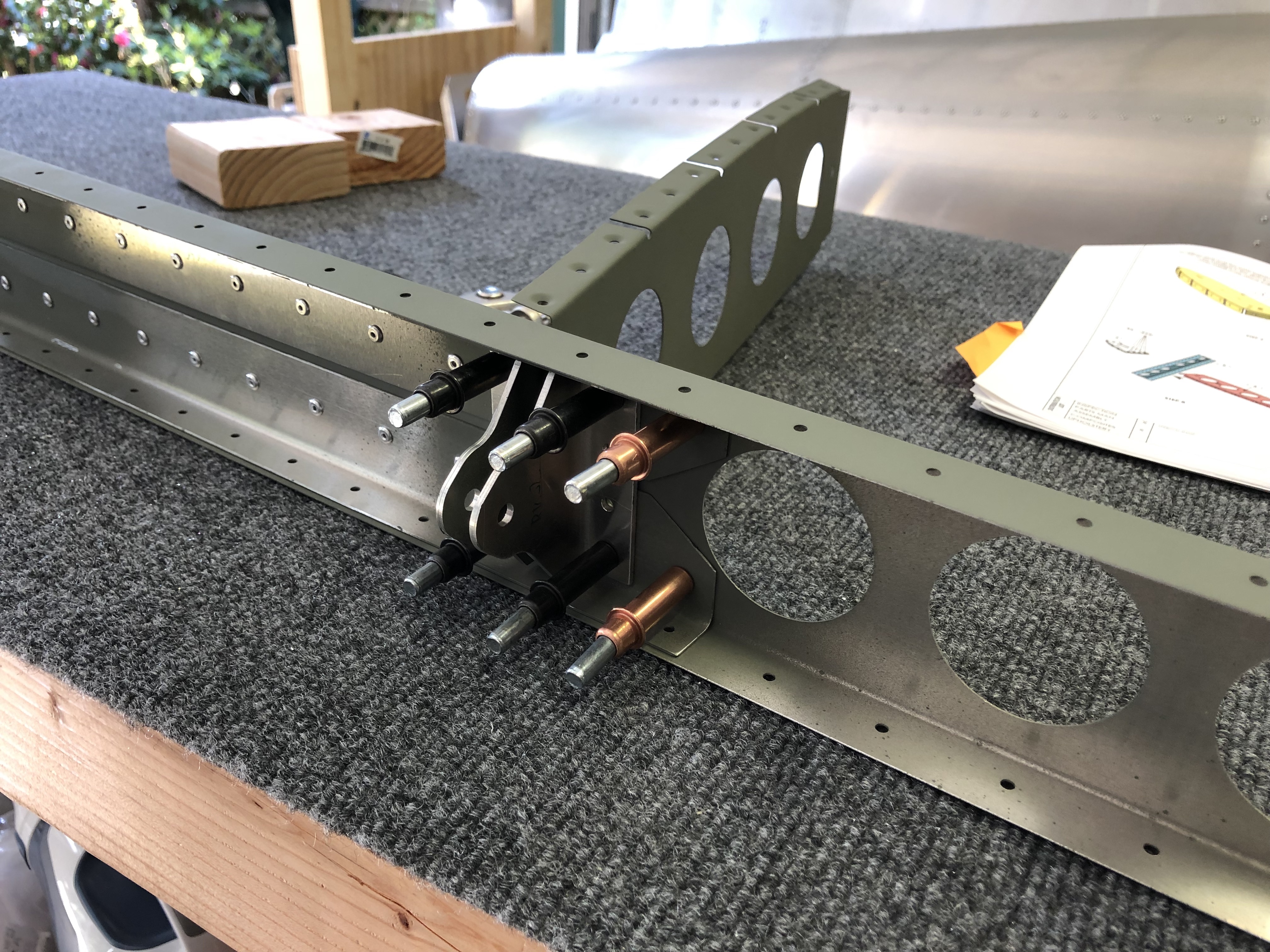
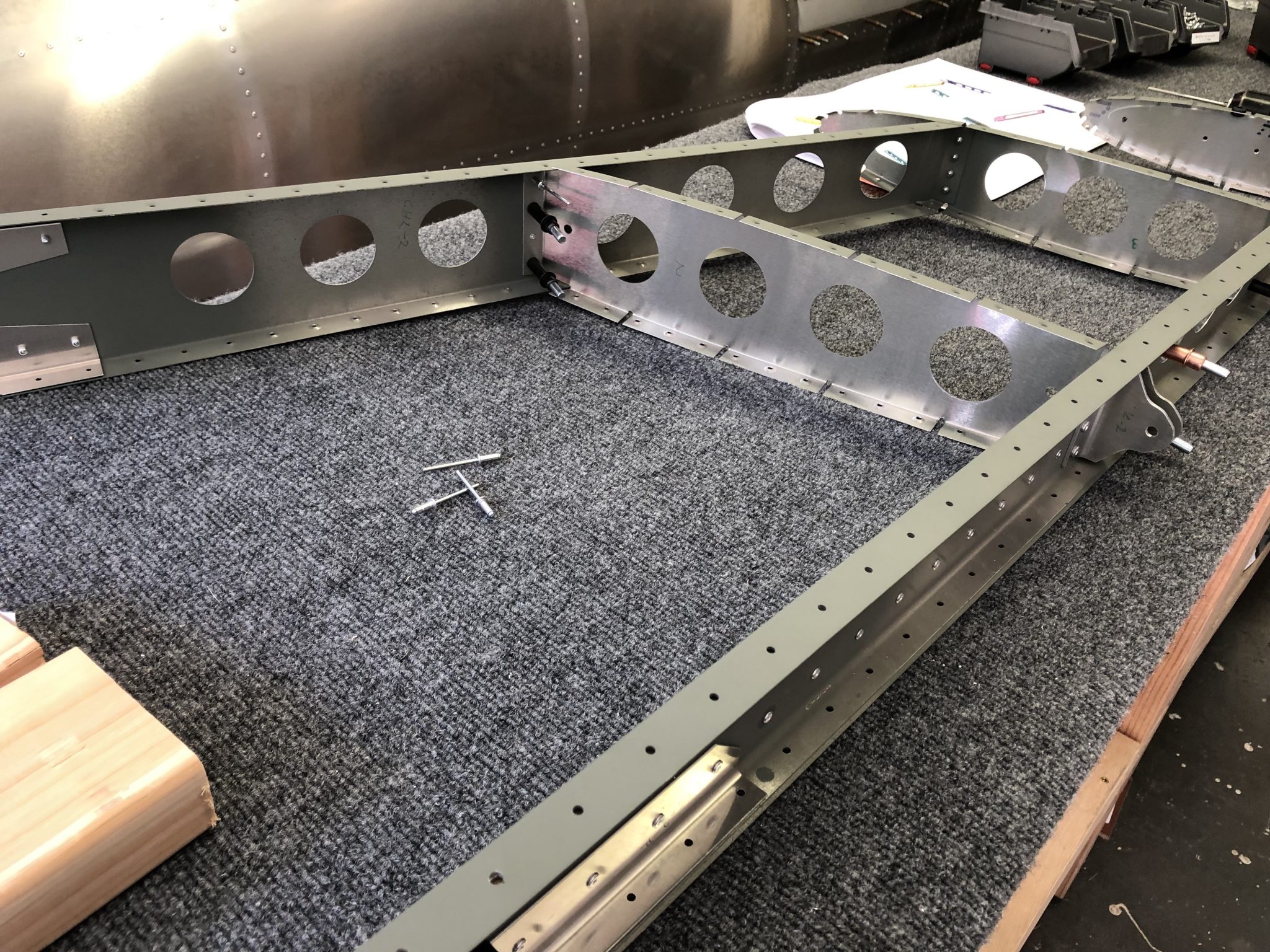
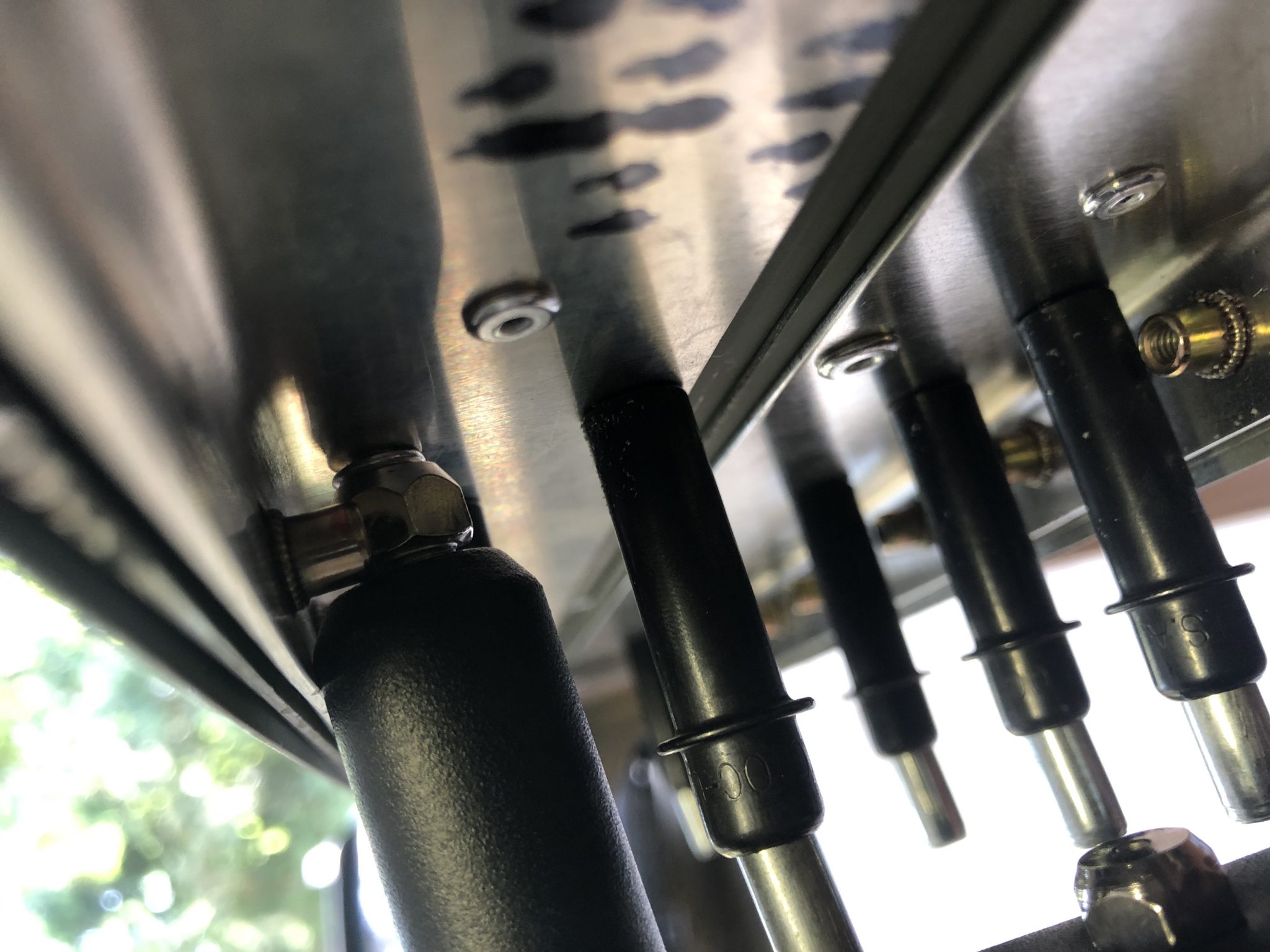
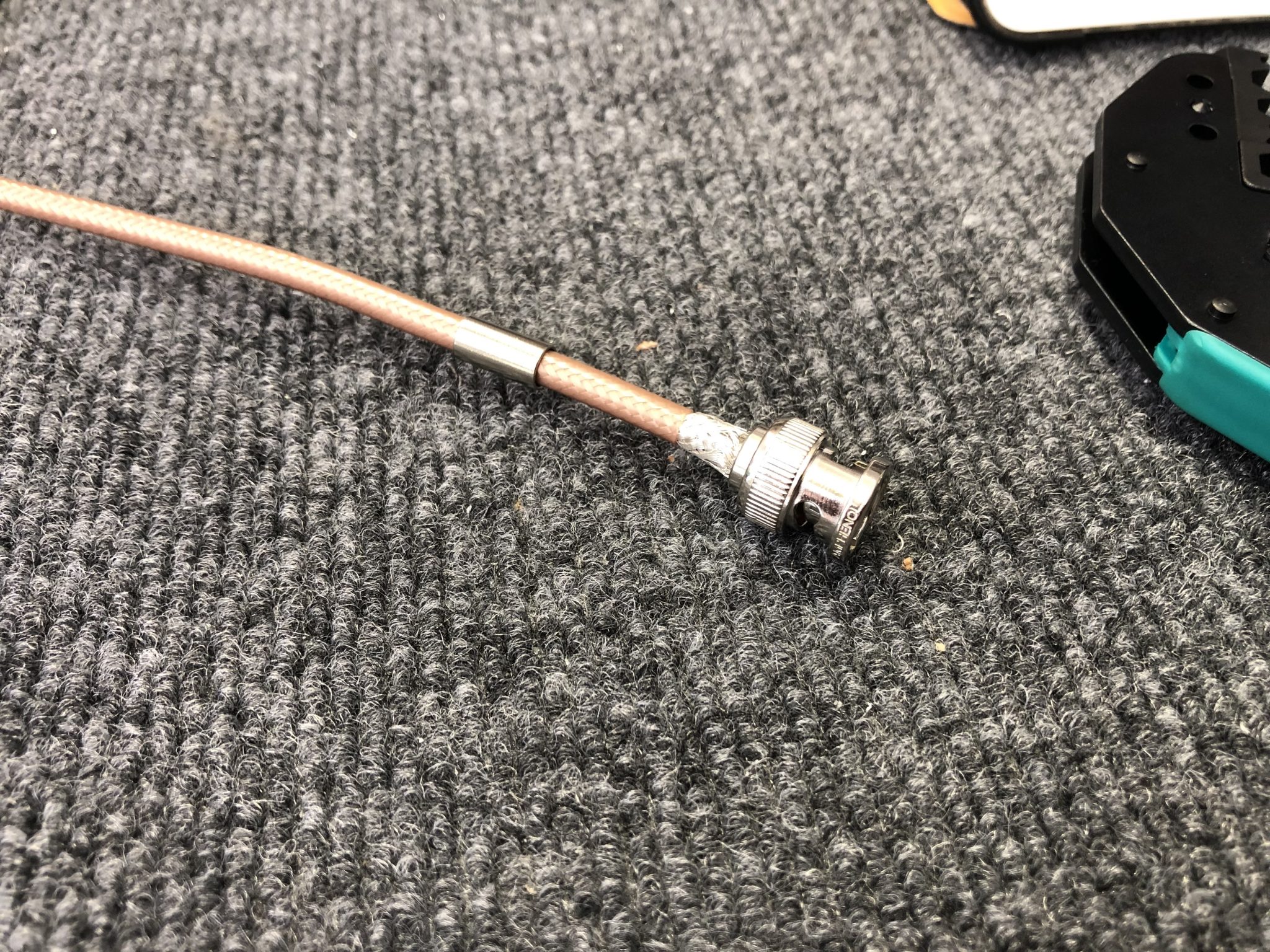
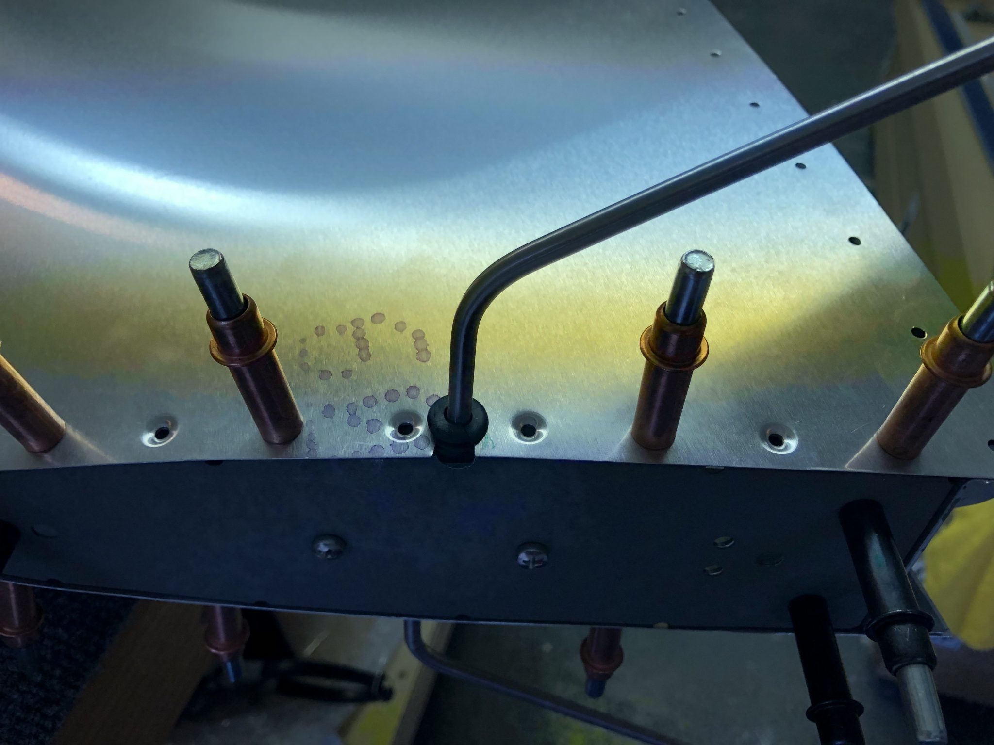
After I had that dialed in, I did another test fit to get the length correct, accounting for the bend towards the tube and then mounted the fittings.

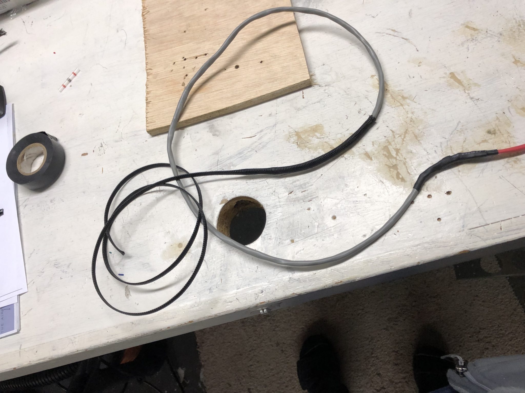
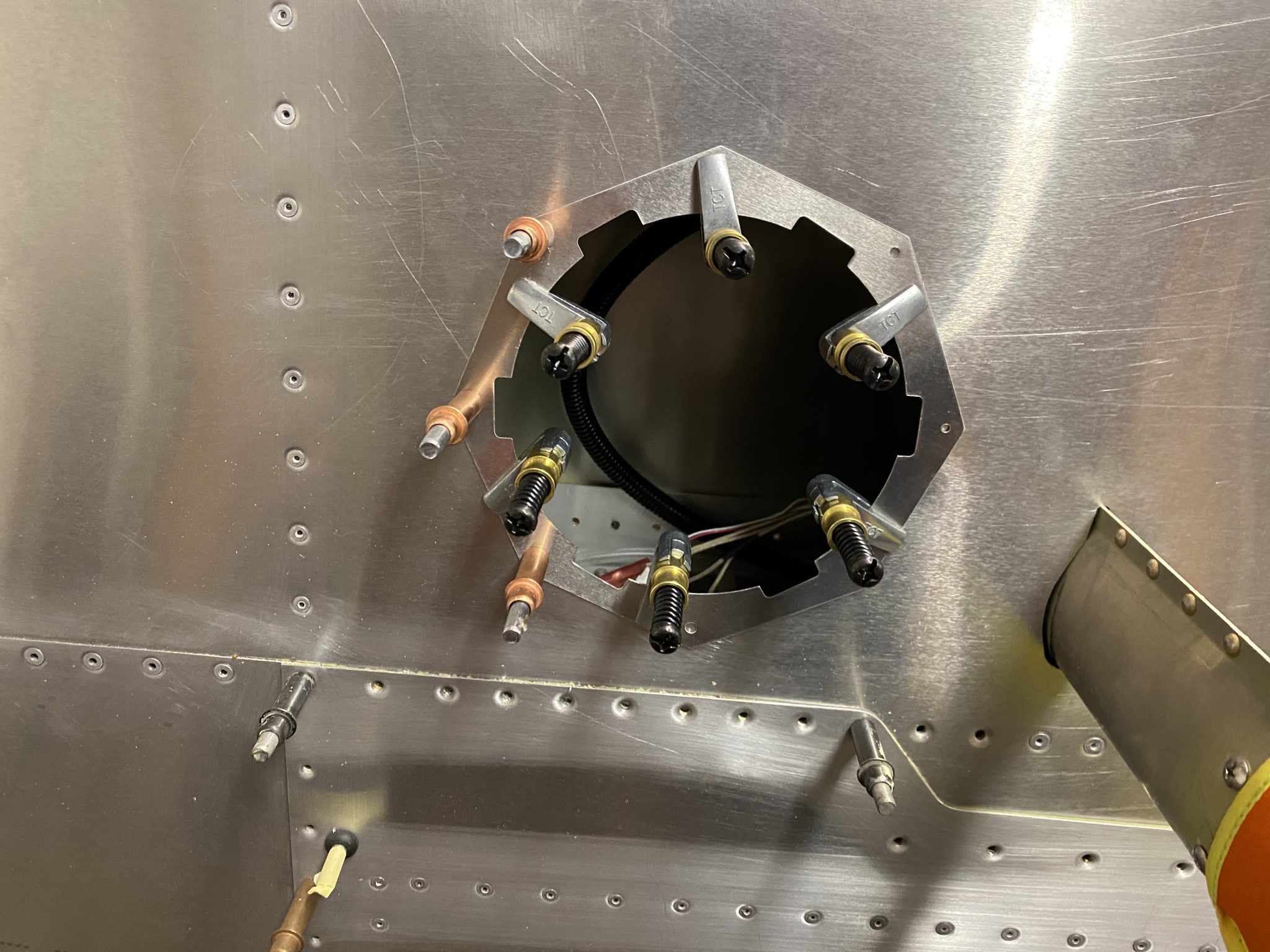
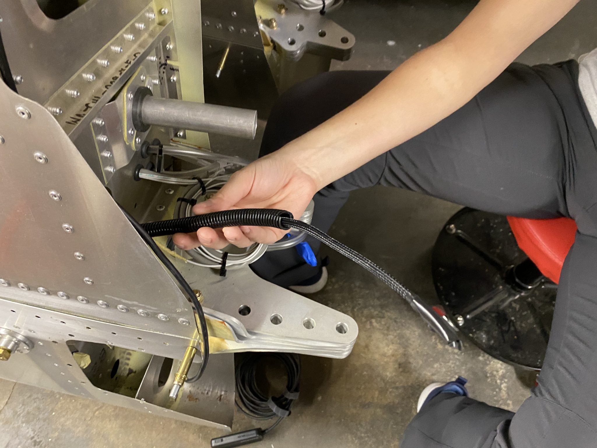
Final fit and connecting to the nylon tubes inside the wing after having cut the nylon tubes.
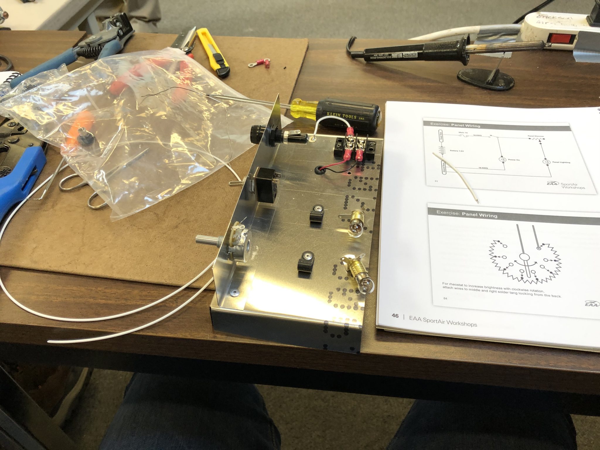
Installing the regulator and wiring
With the Pitot Tube itself installed, time to finish the regulator and wiring that controls the heating of the Pitot Tube.
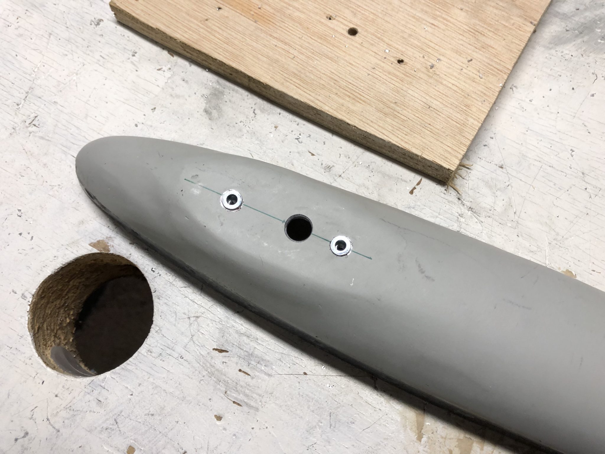
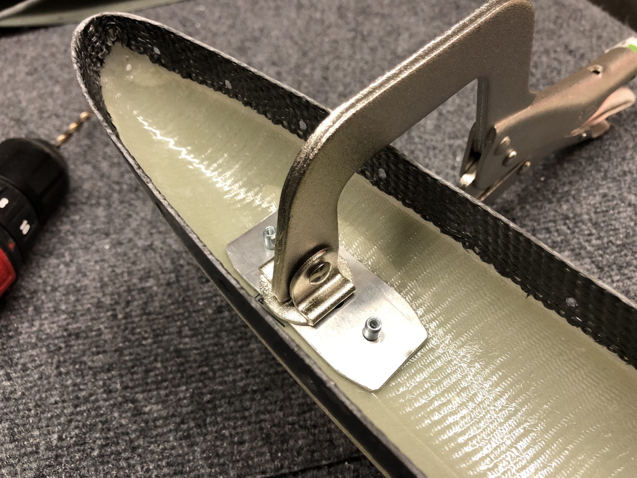
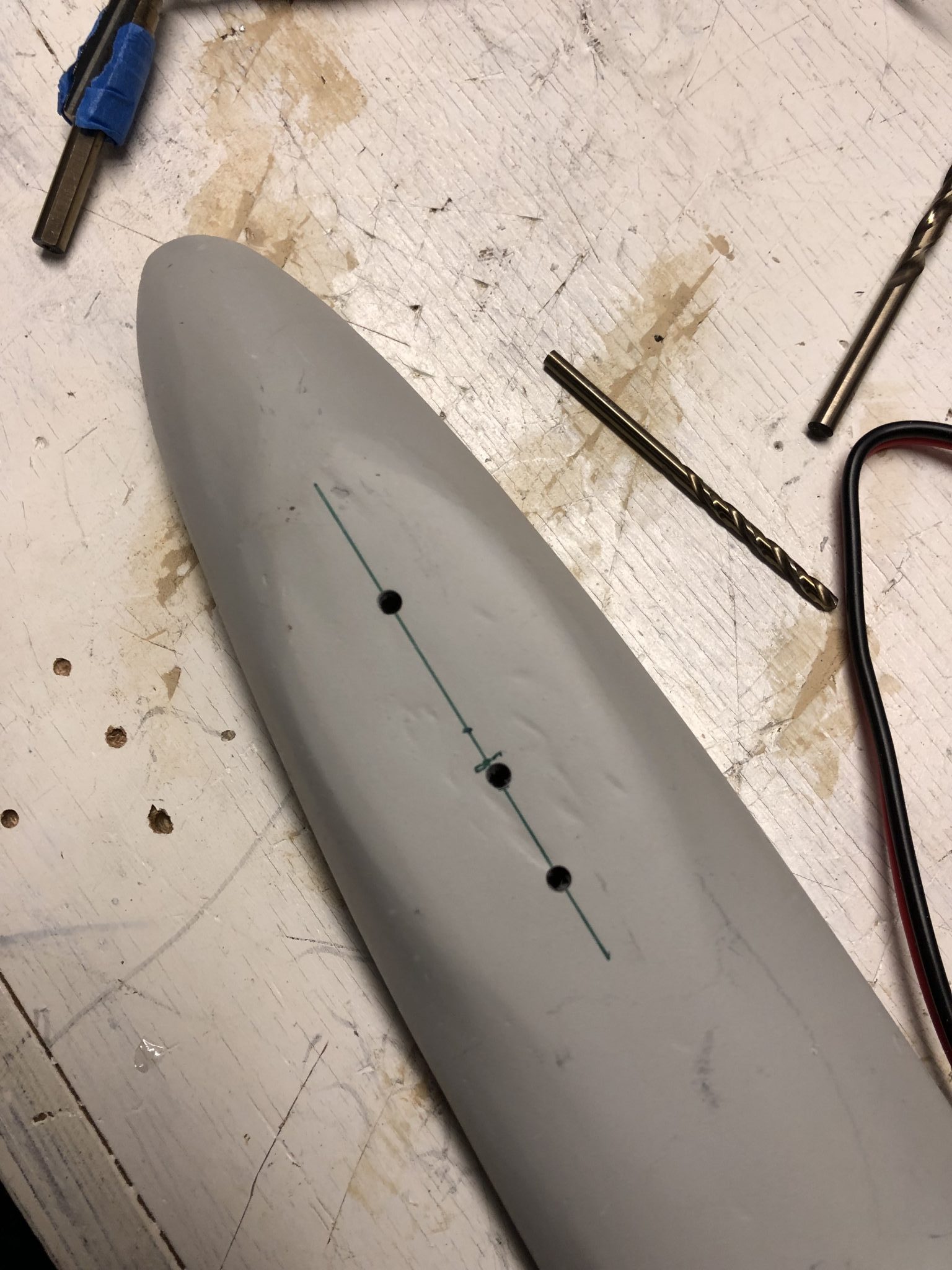
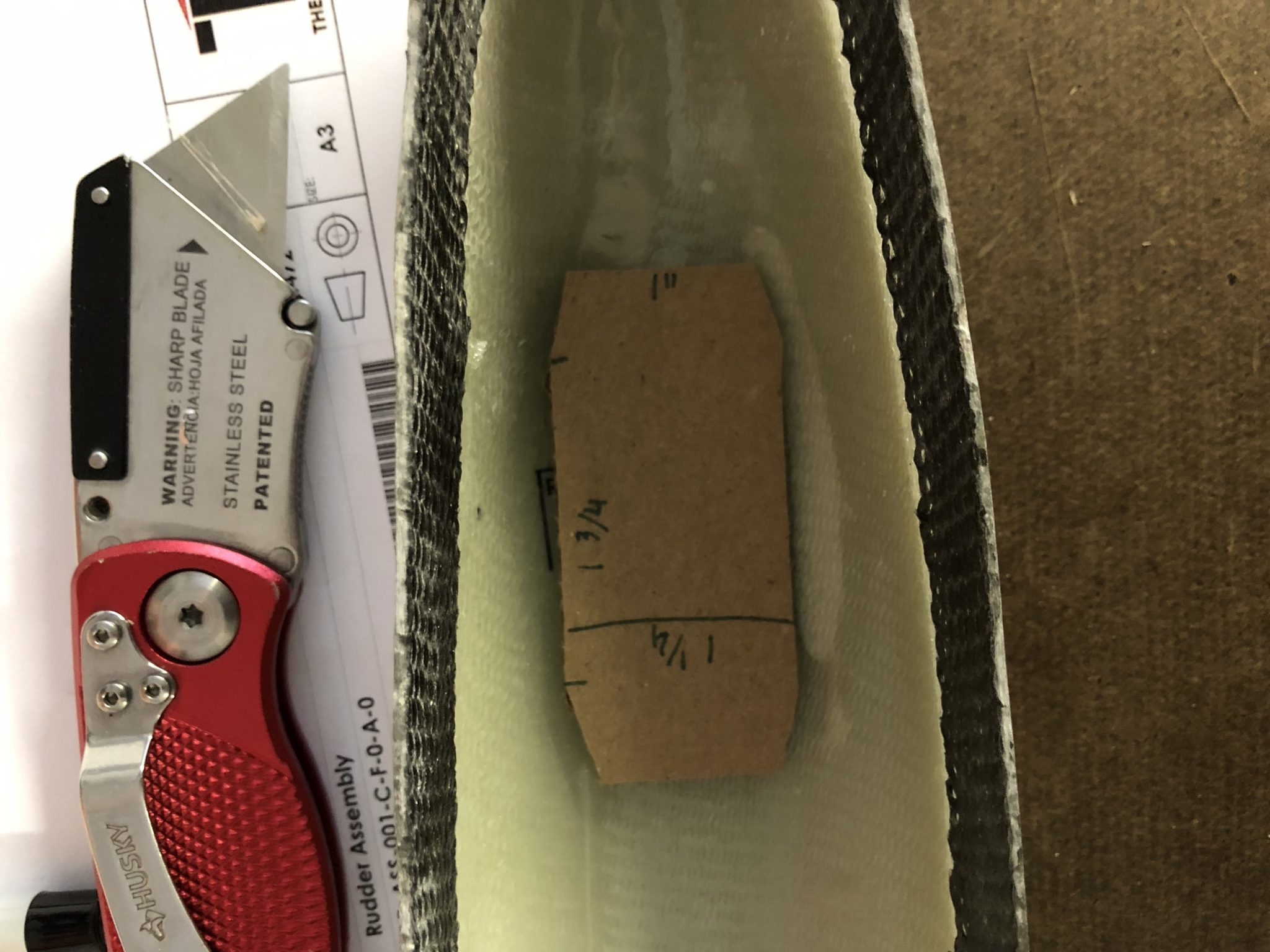
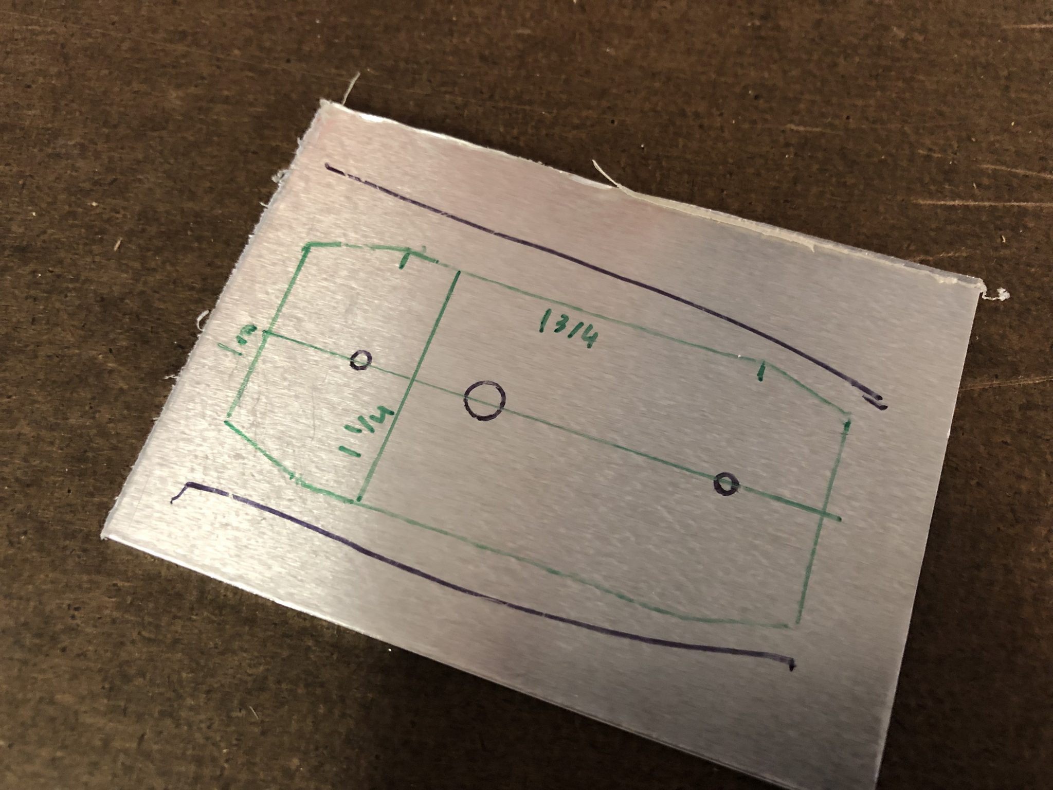
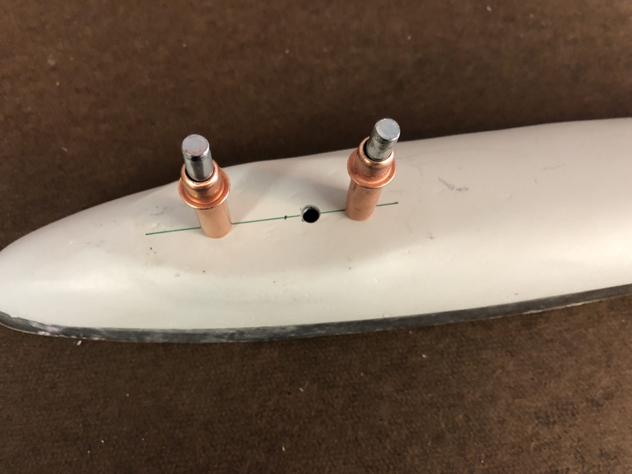
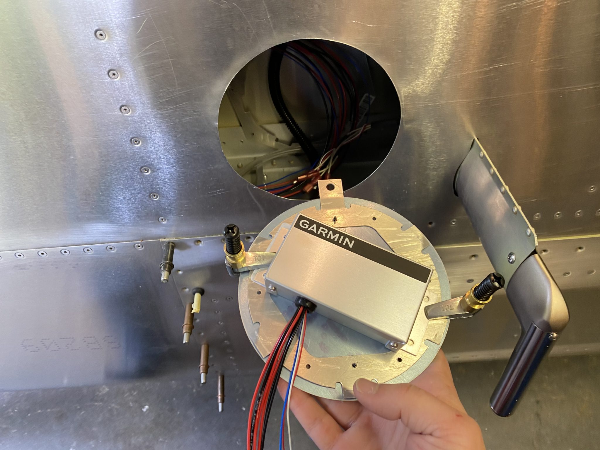
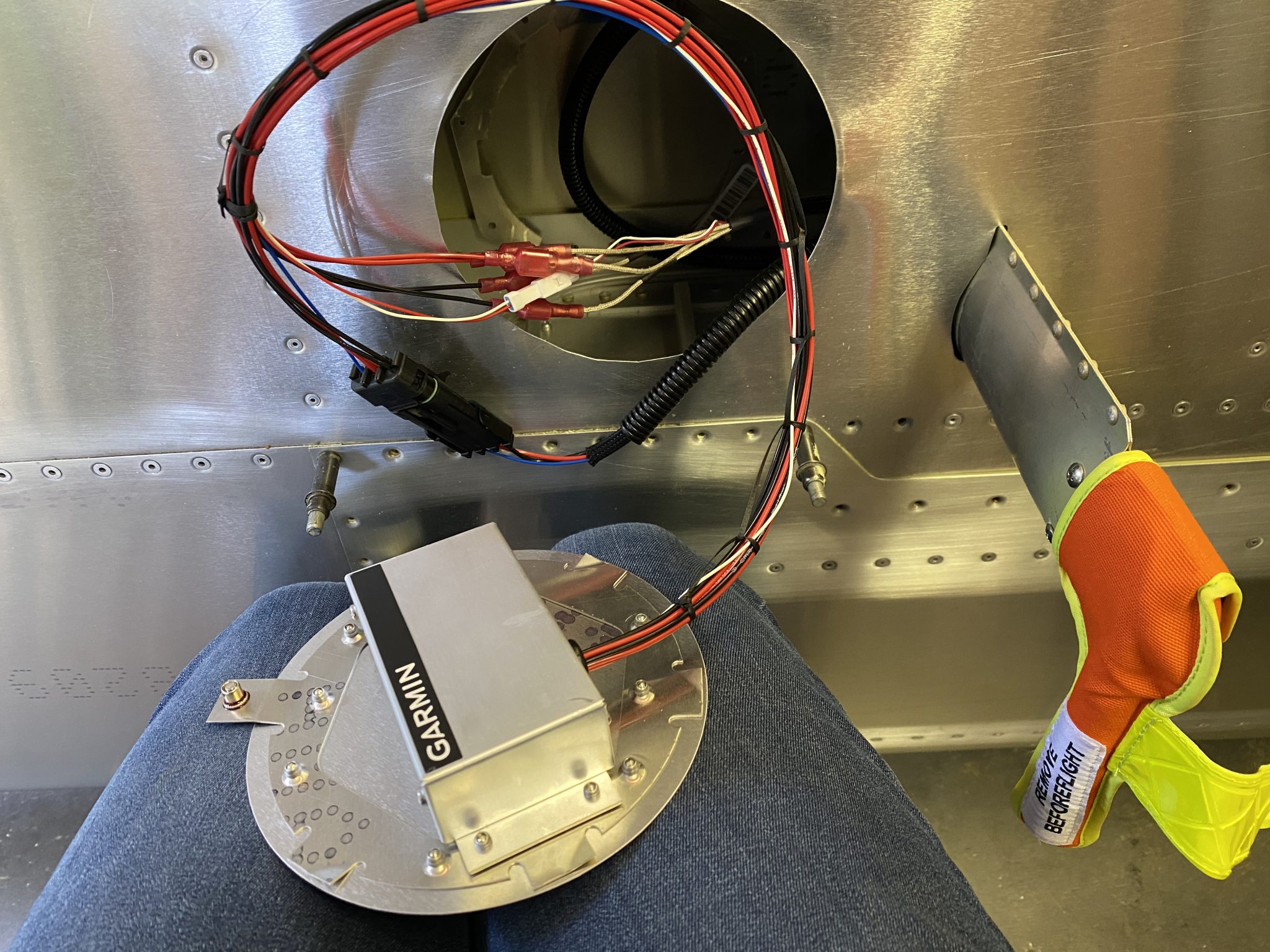
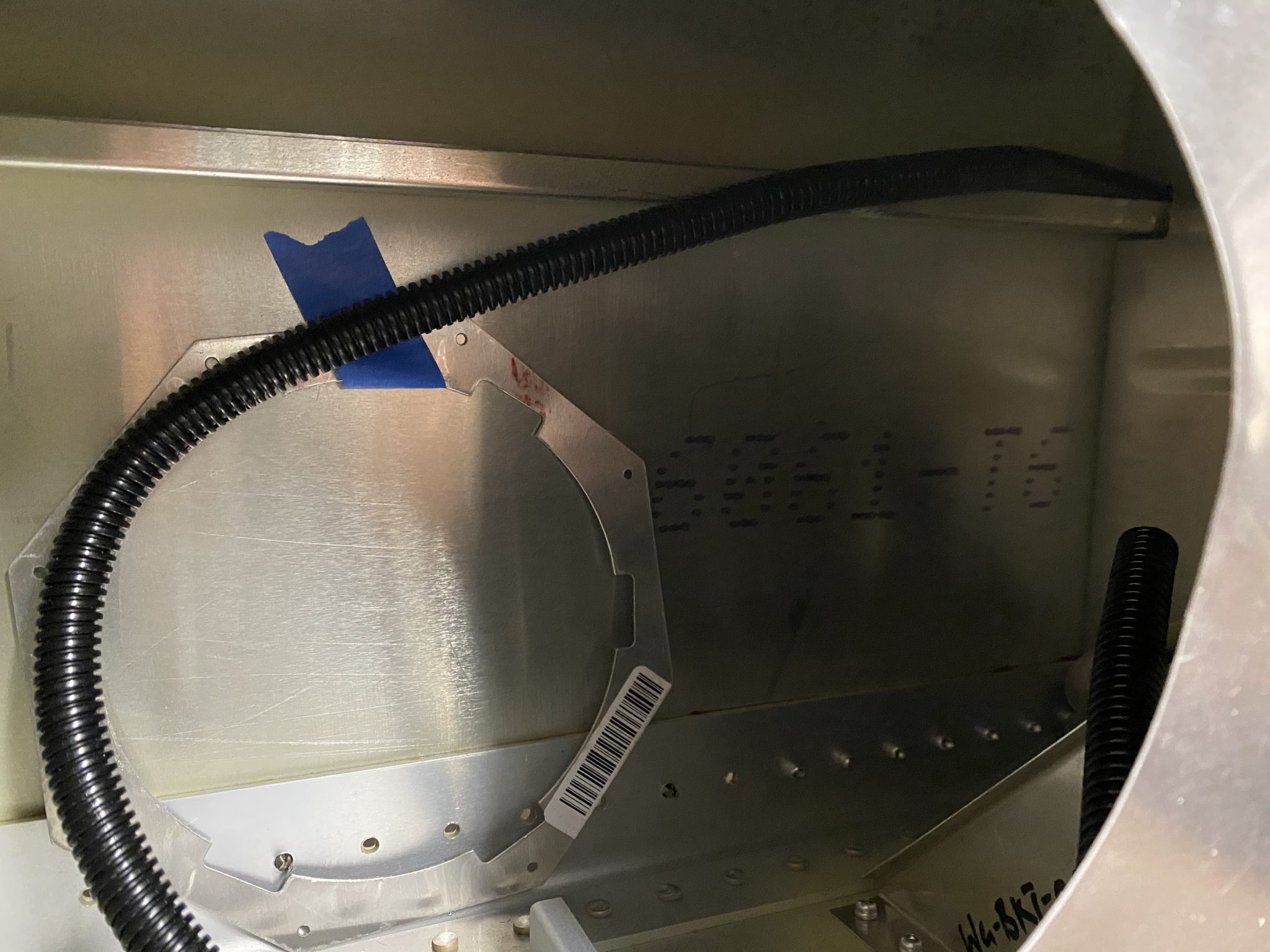
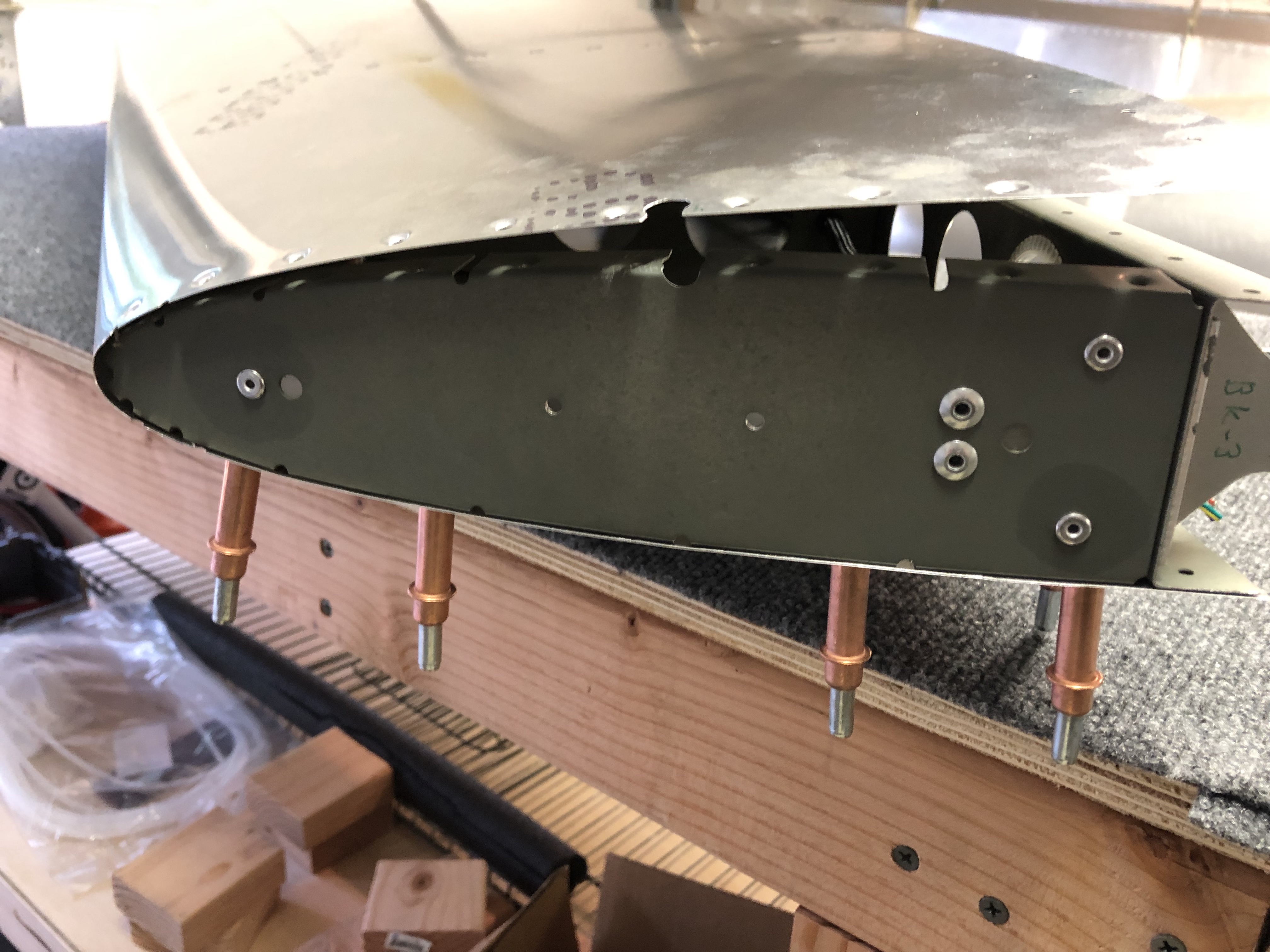
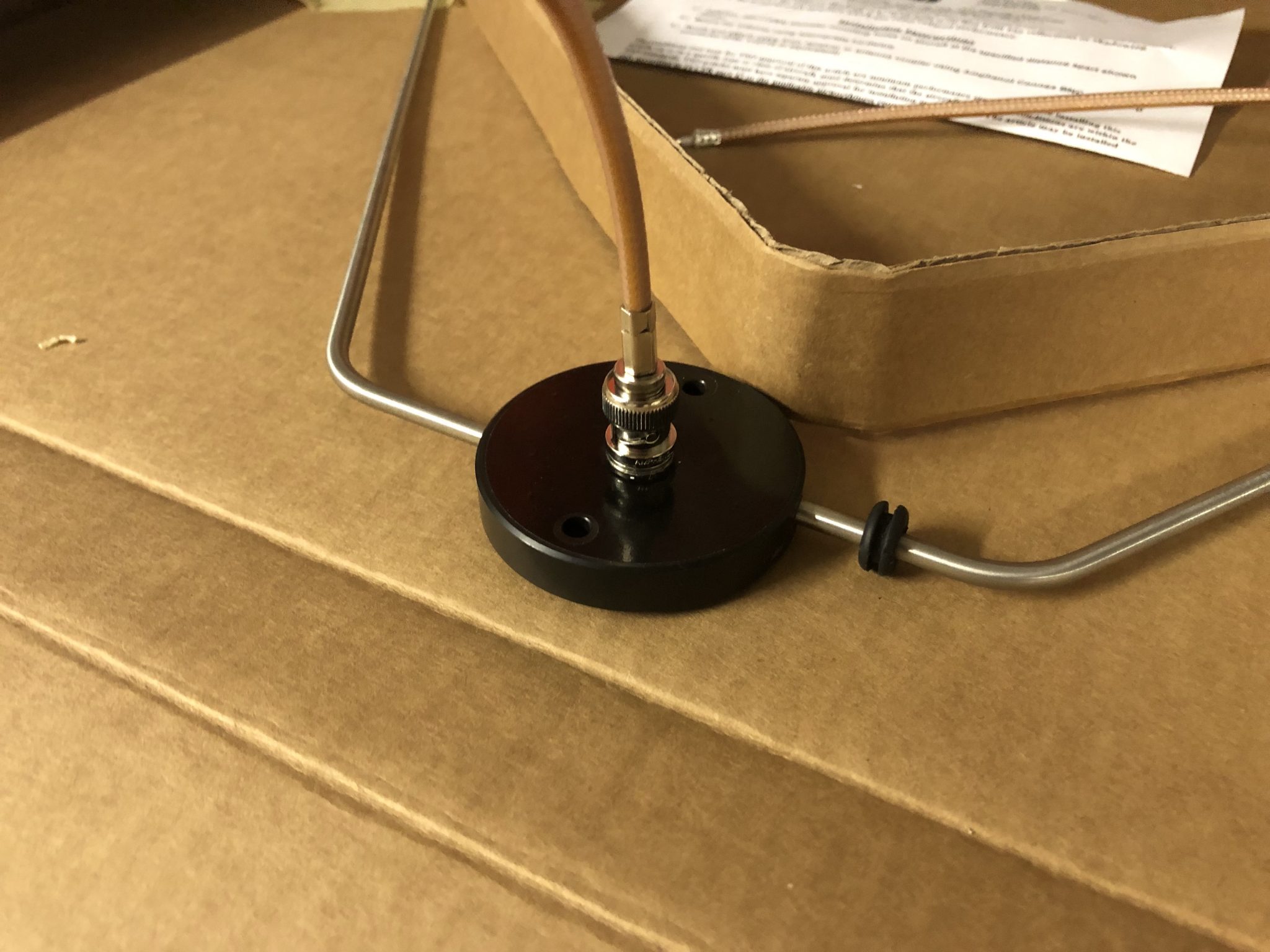
As I explained previously, I plan to mount the regulator unit onto the inspection panel plate, so I did some measuring and orienting to make sure the twist action of the round plate wouldn’t interfere with the wires coming out of the regulator.
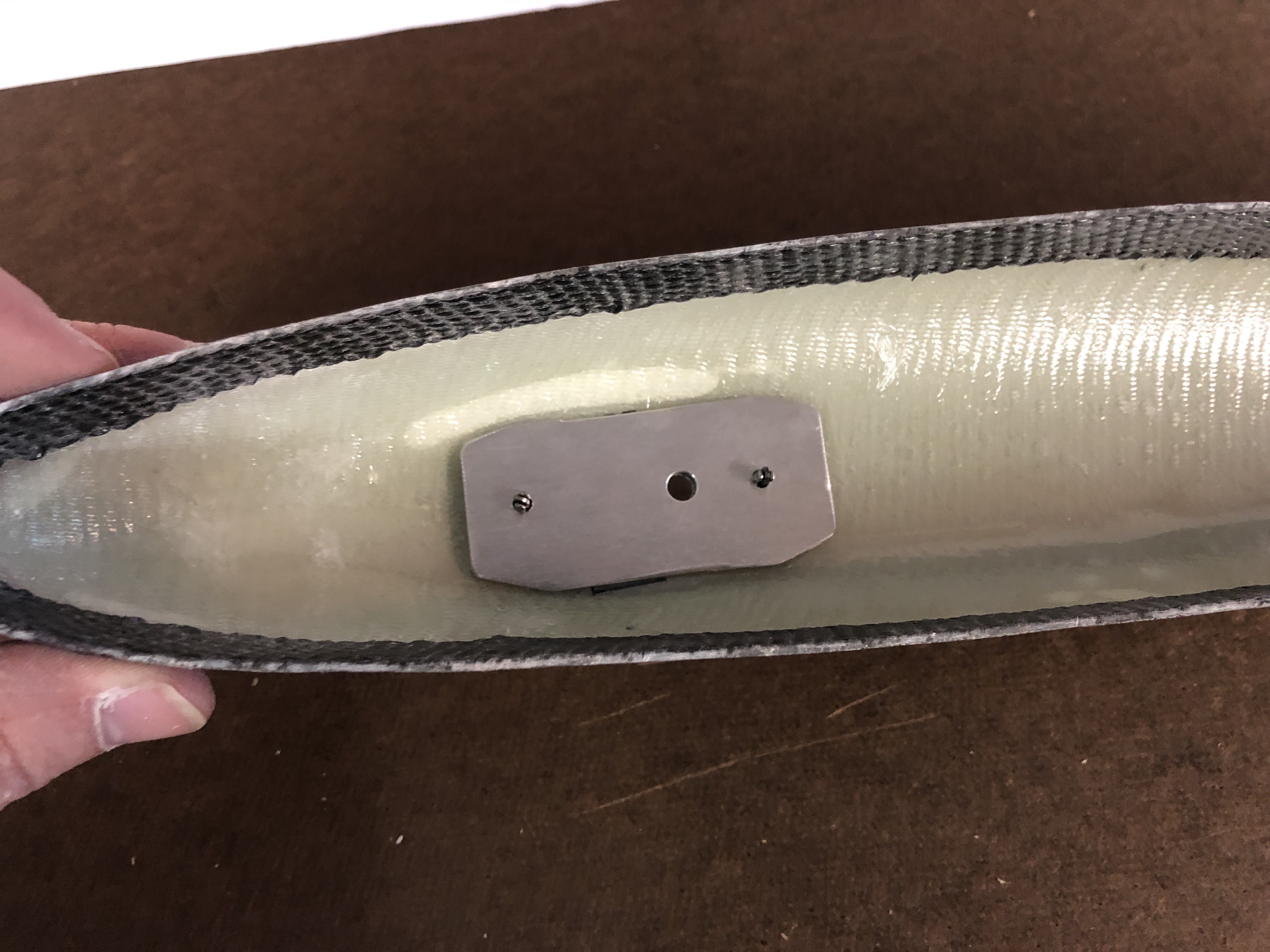
Here is the final orientation that I figured out would work best (the screw will mount to the bottom, so the wires will come out the top):
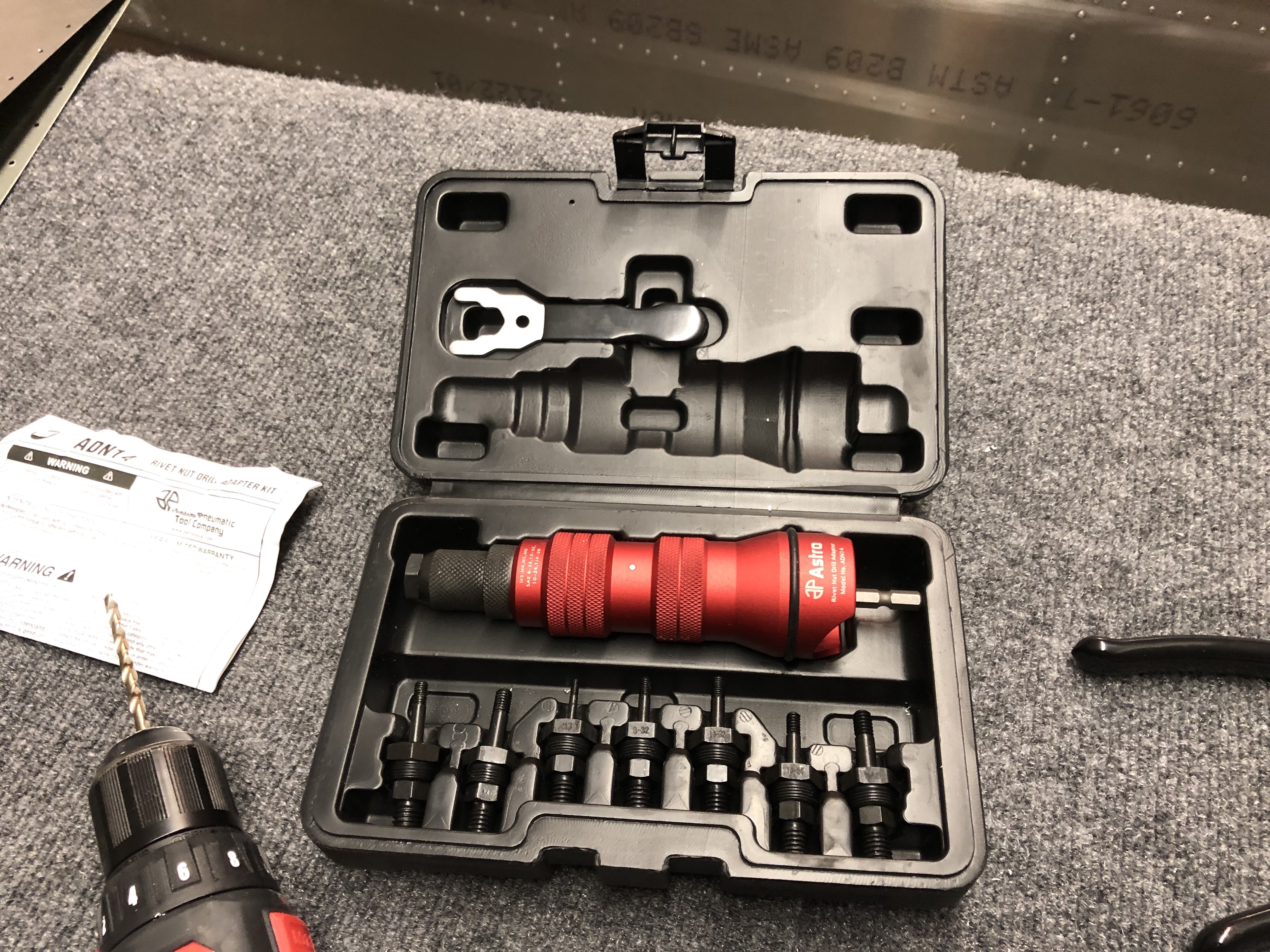
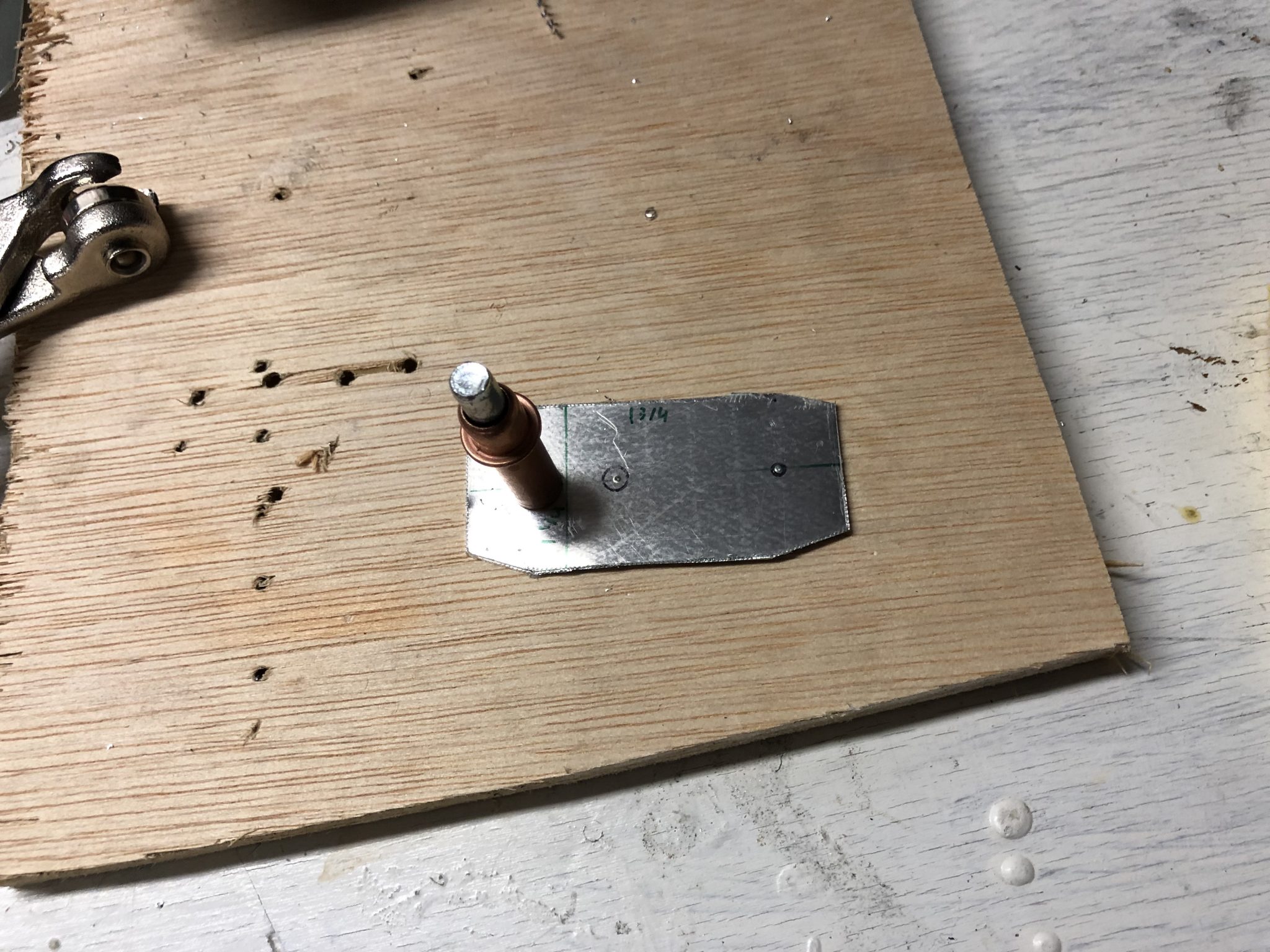
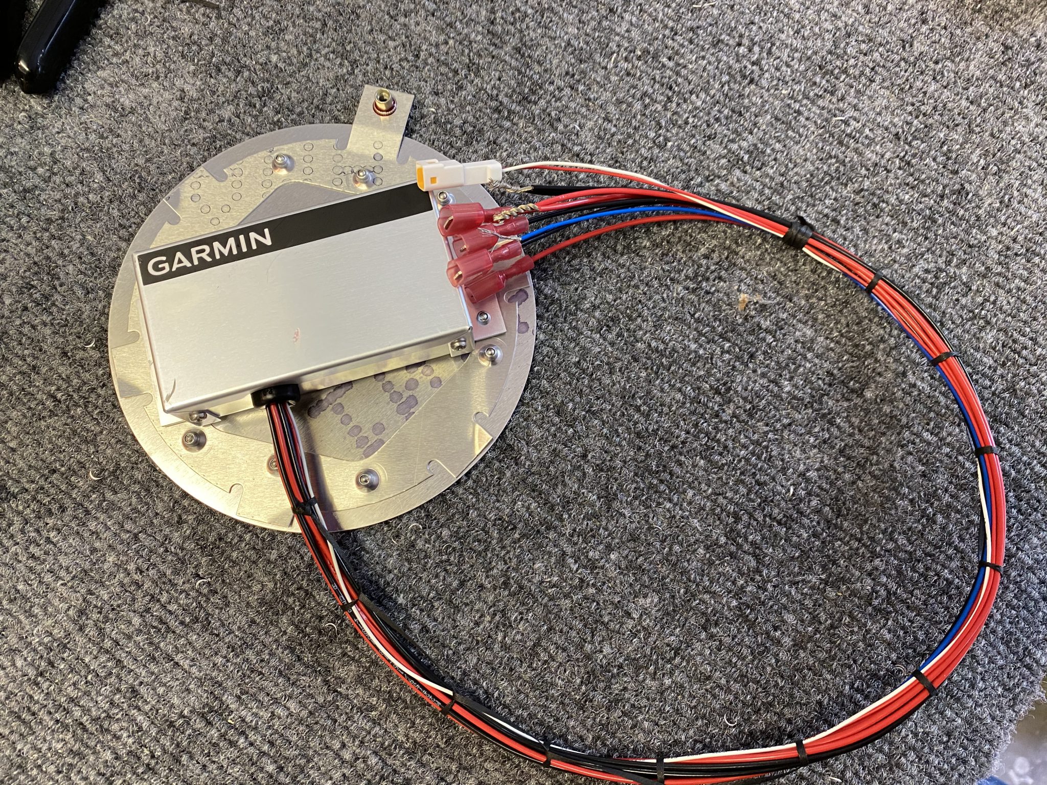
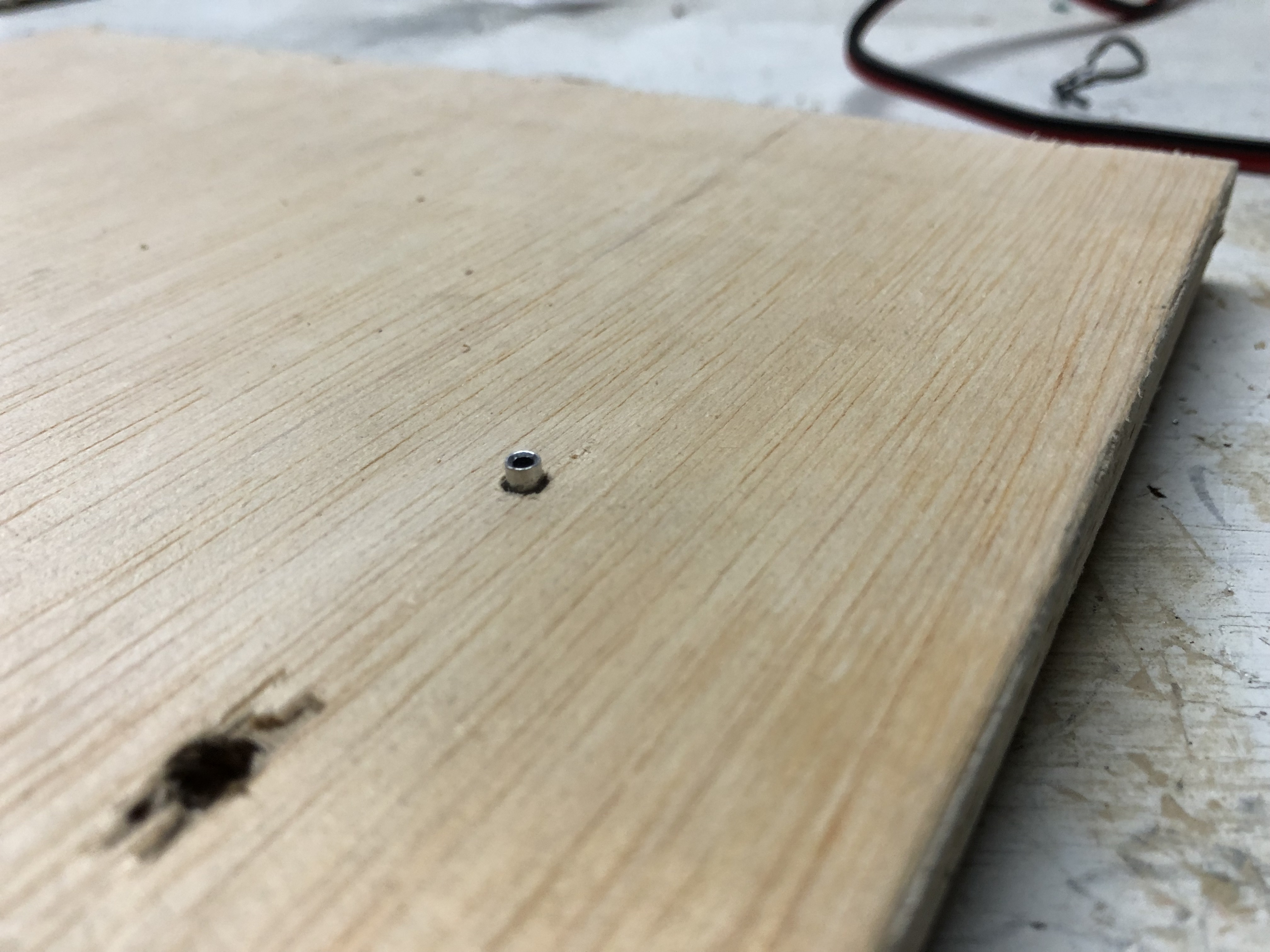
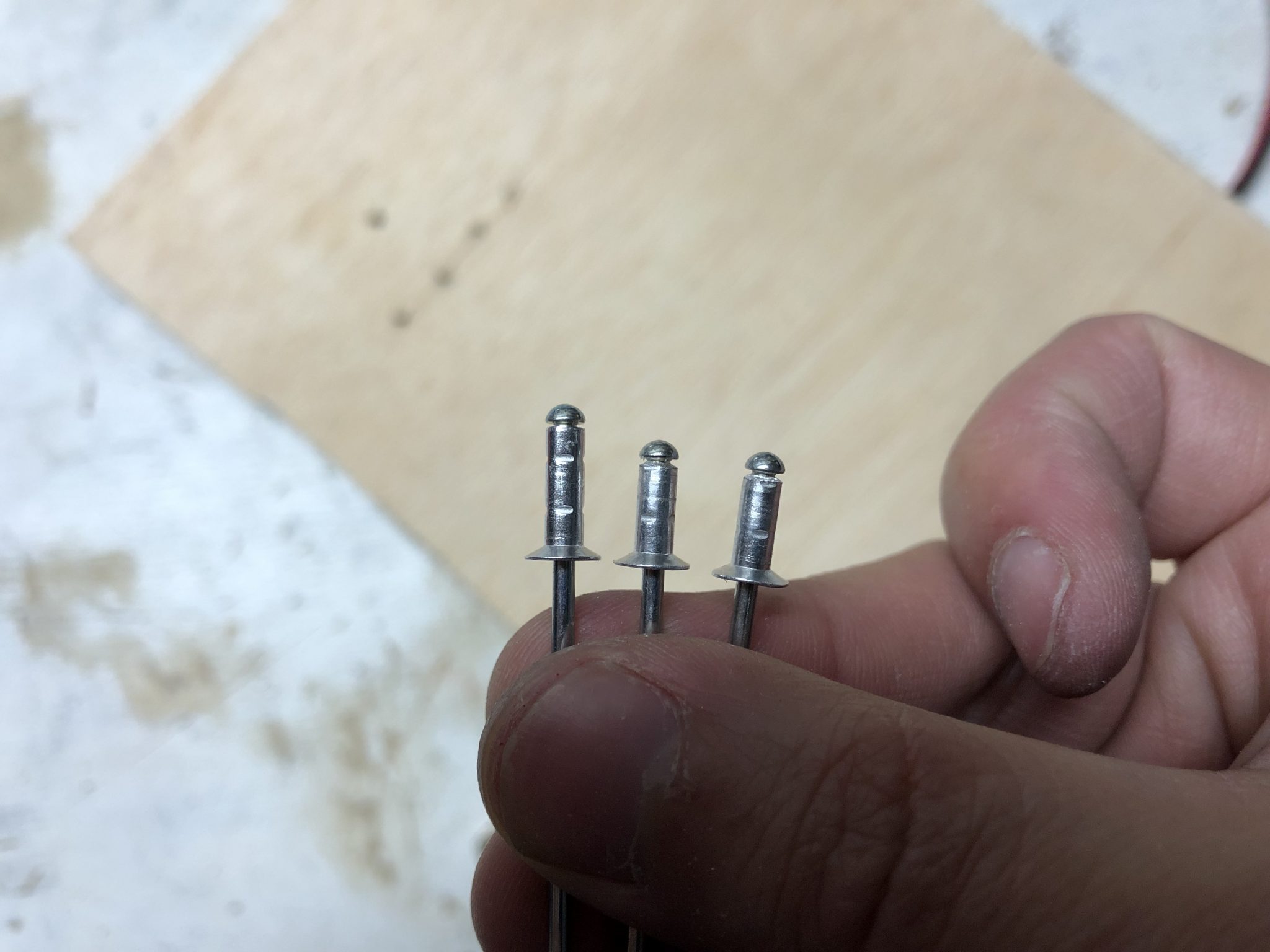
I contemplated between screwing or riveting it on, but I figured that it’s unlikely that it will need to be changed out frequently, so I riveted it onto the plate.
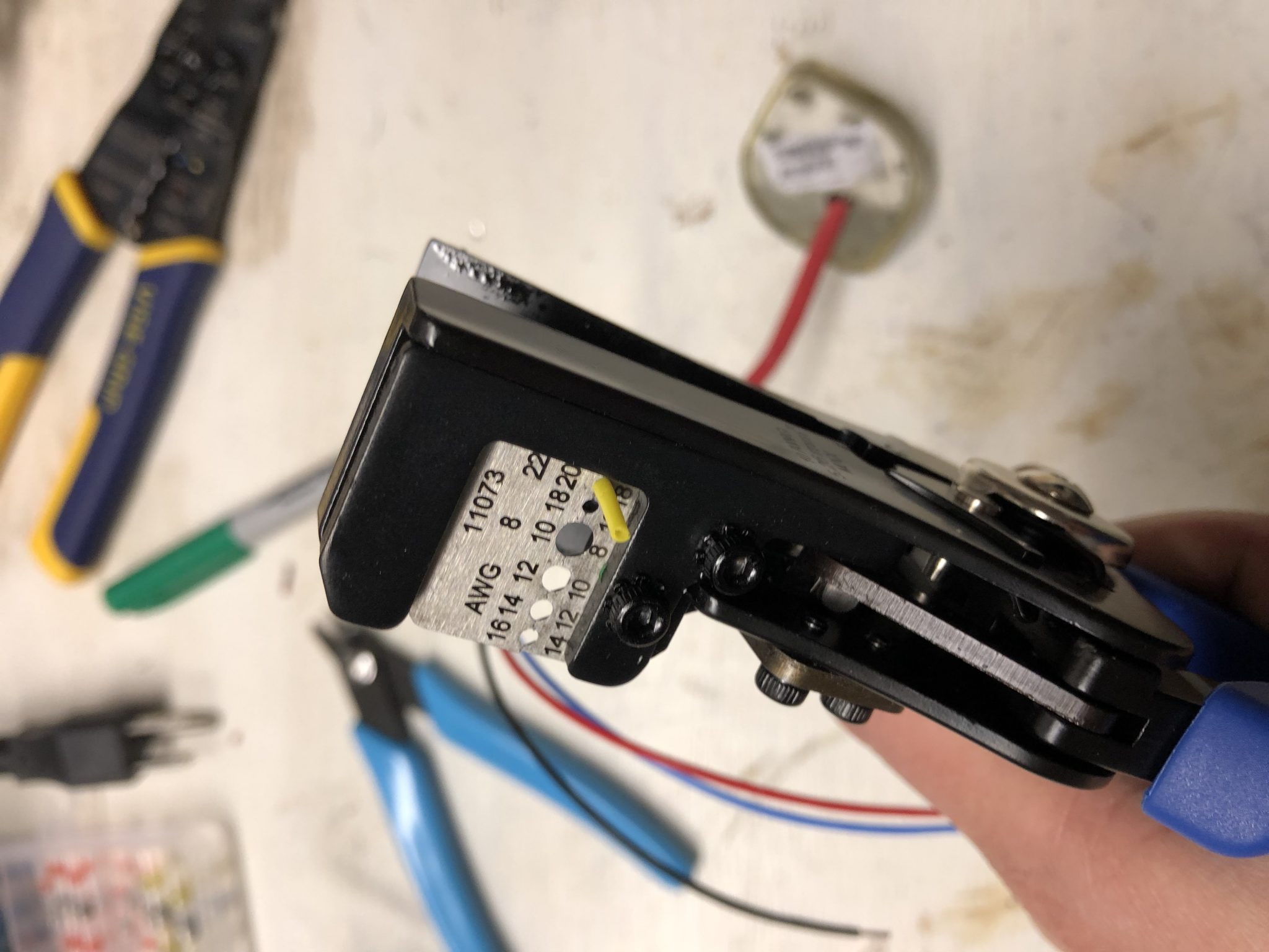
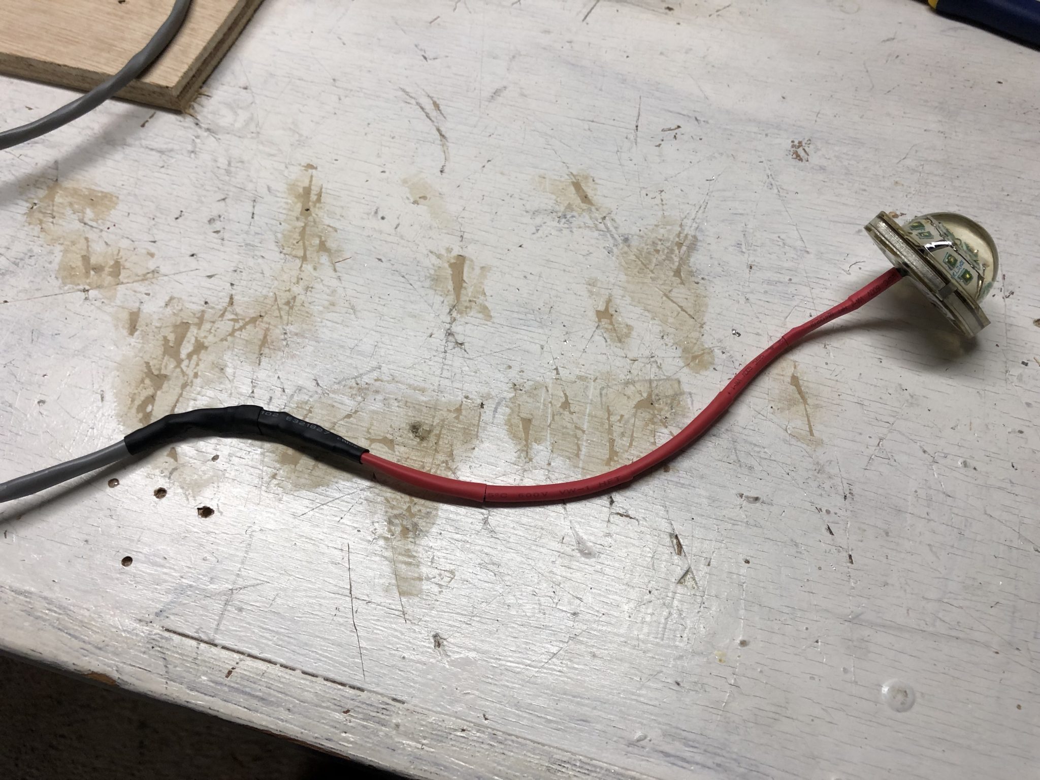
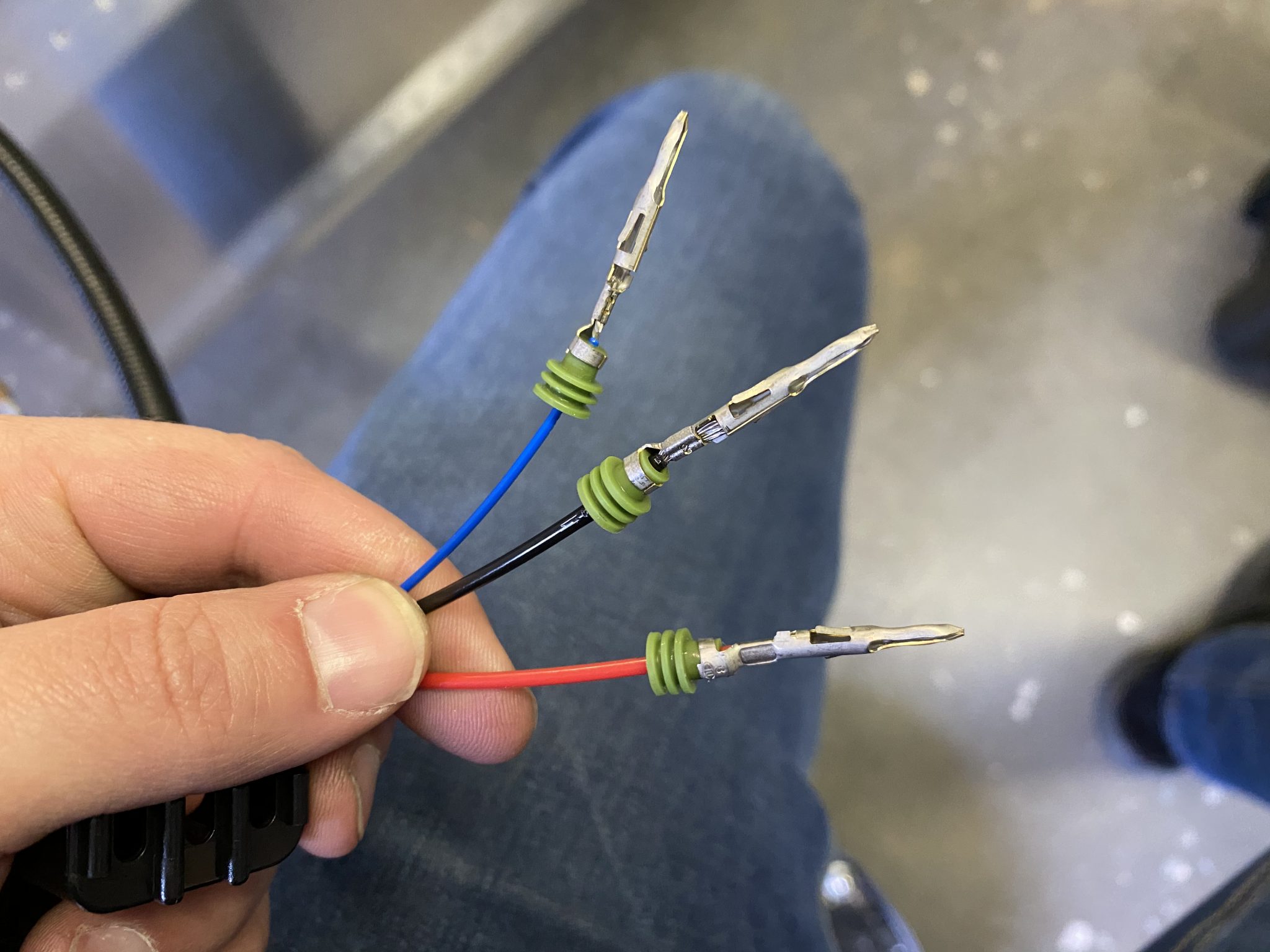
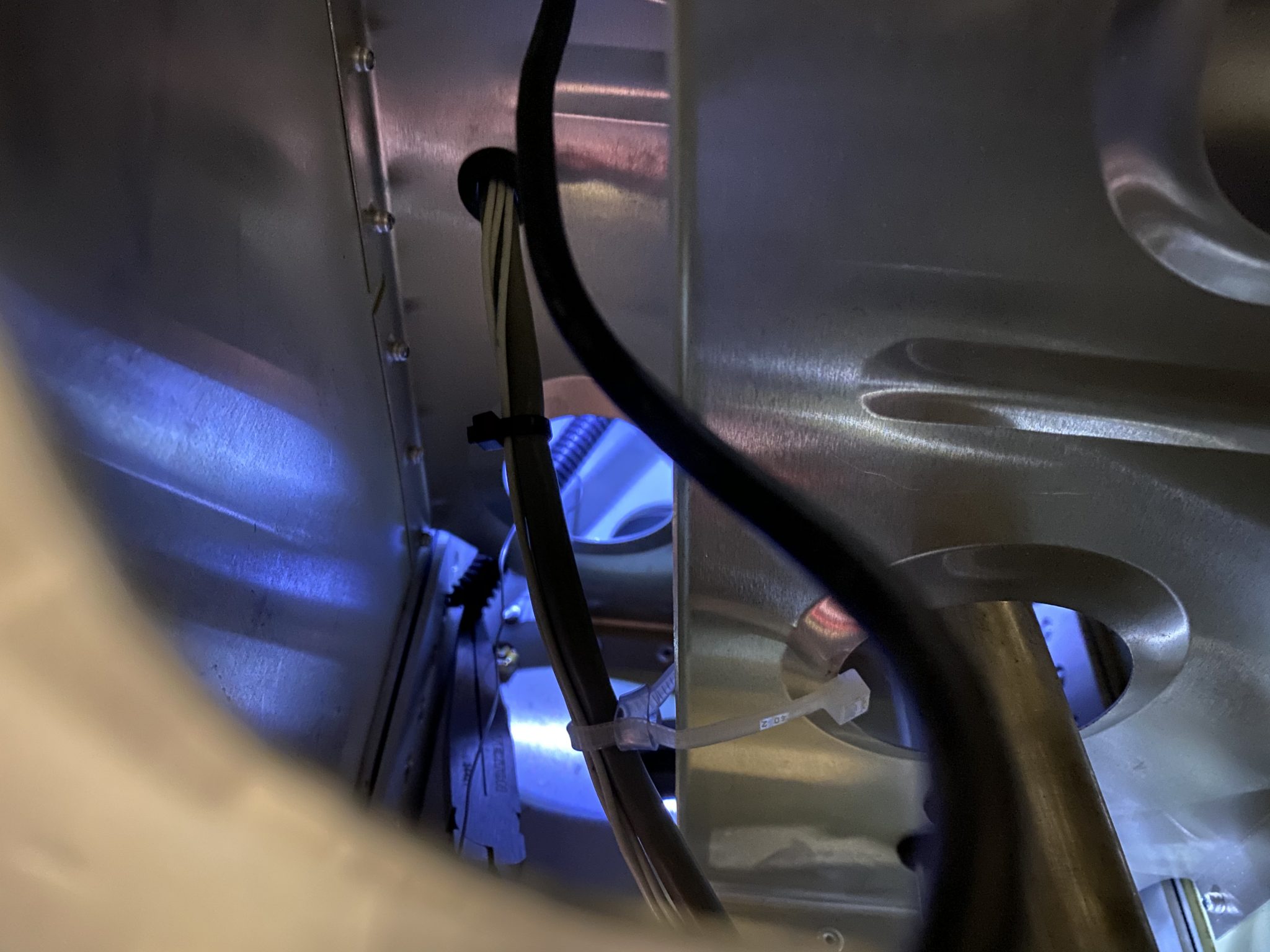
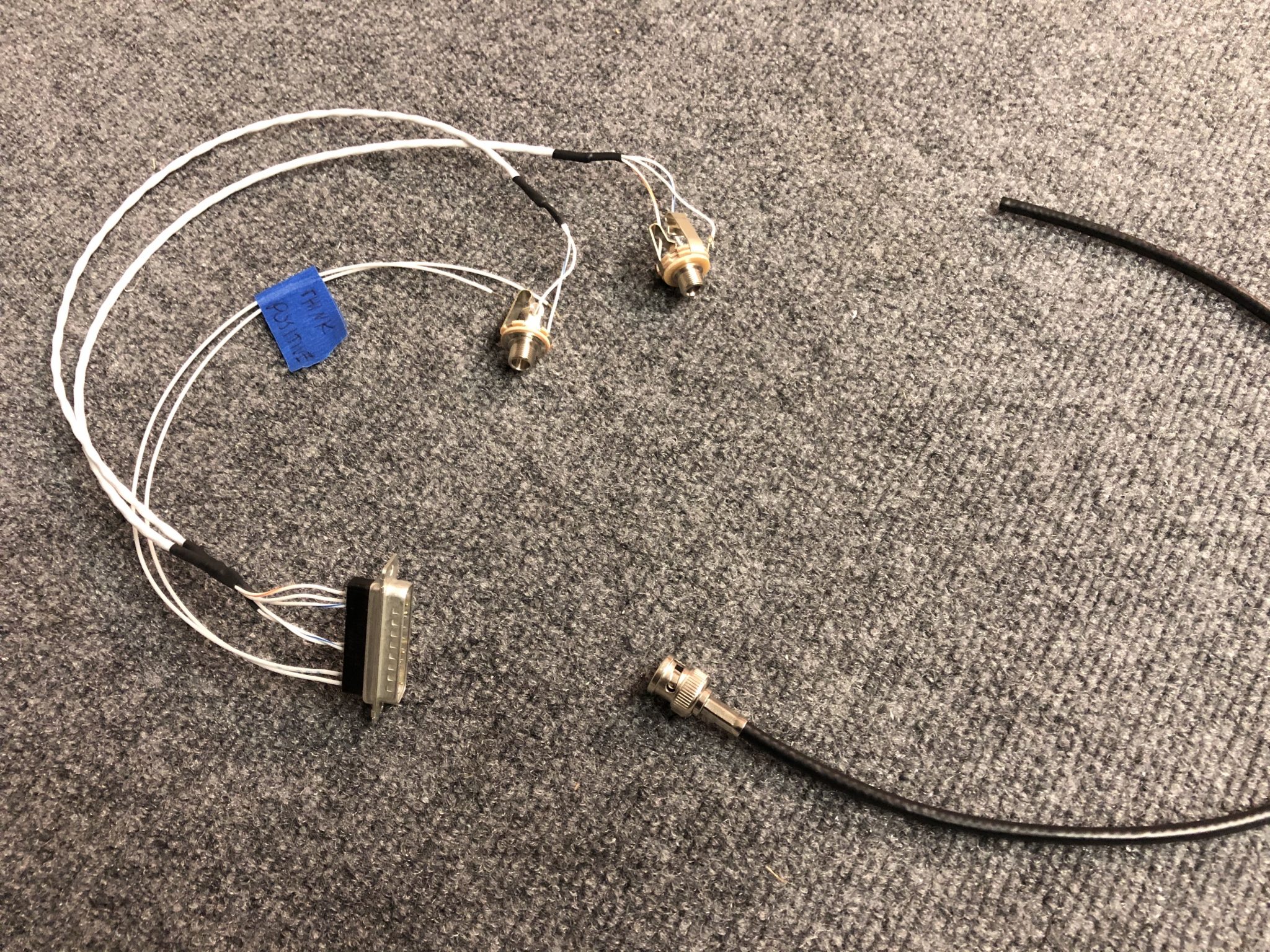
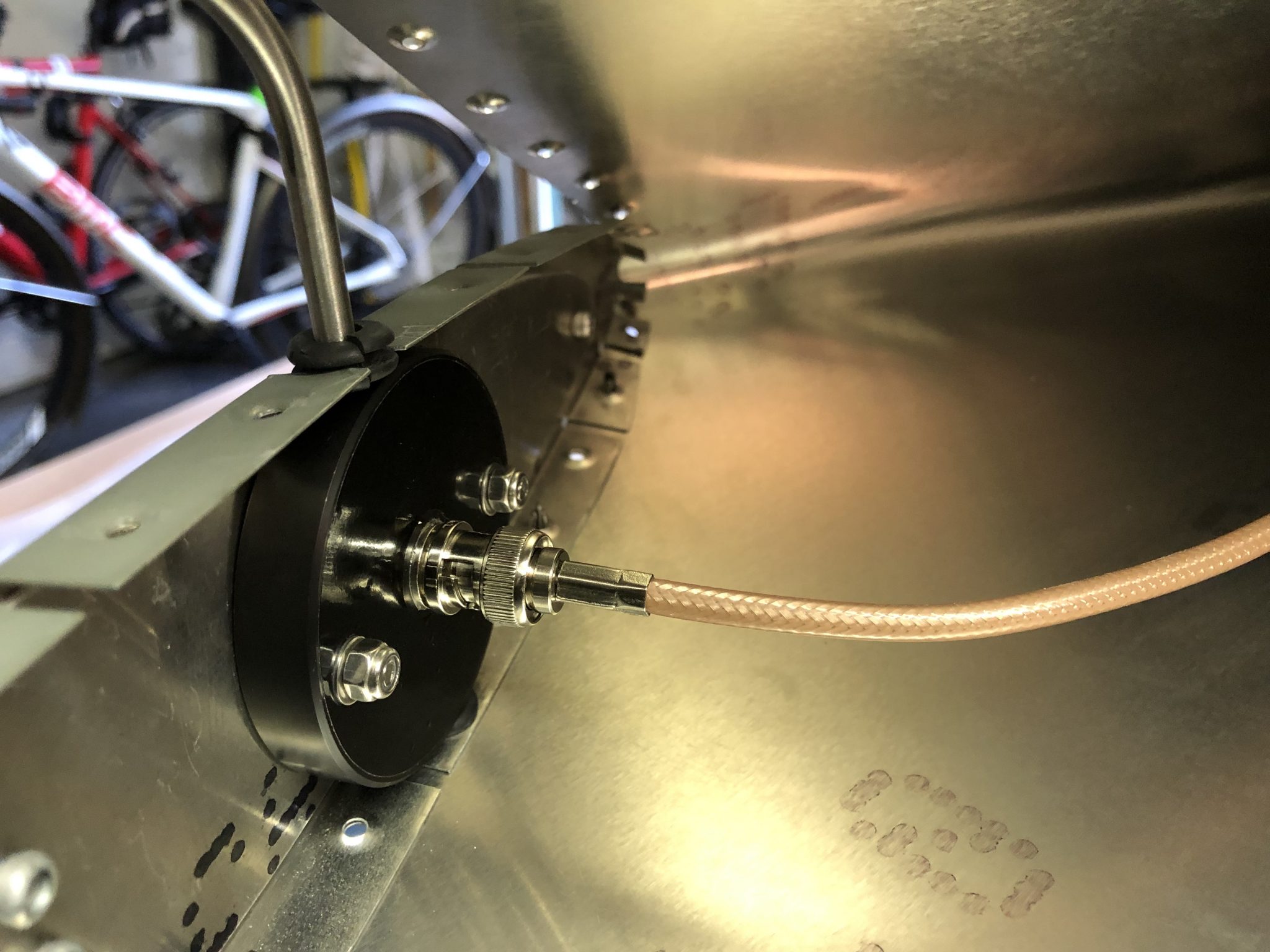
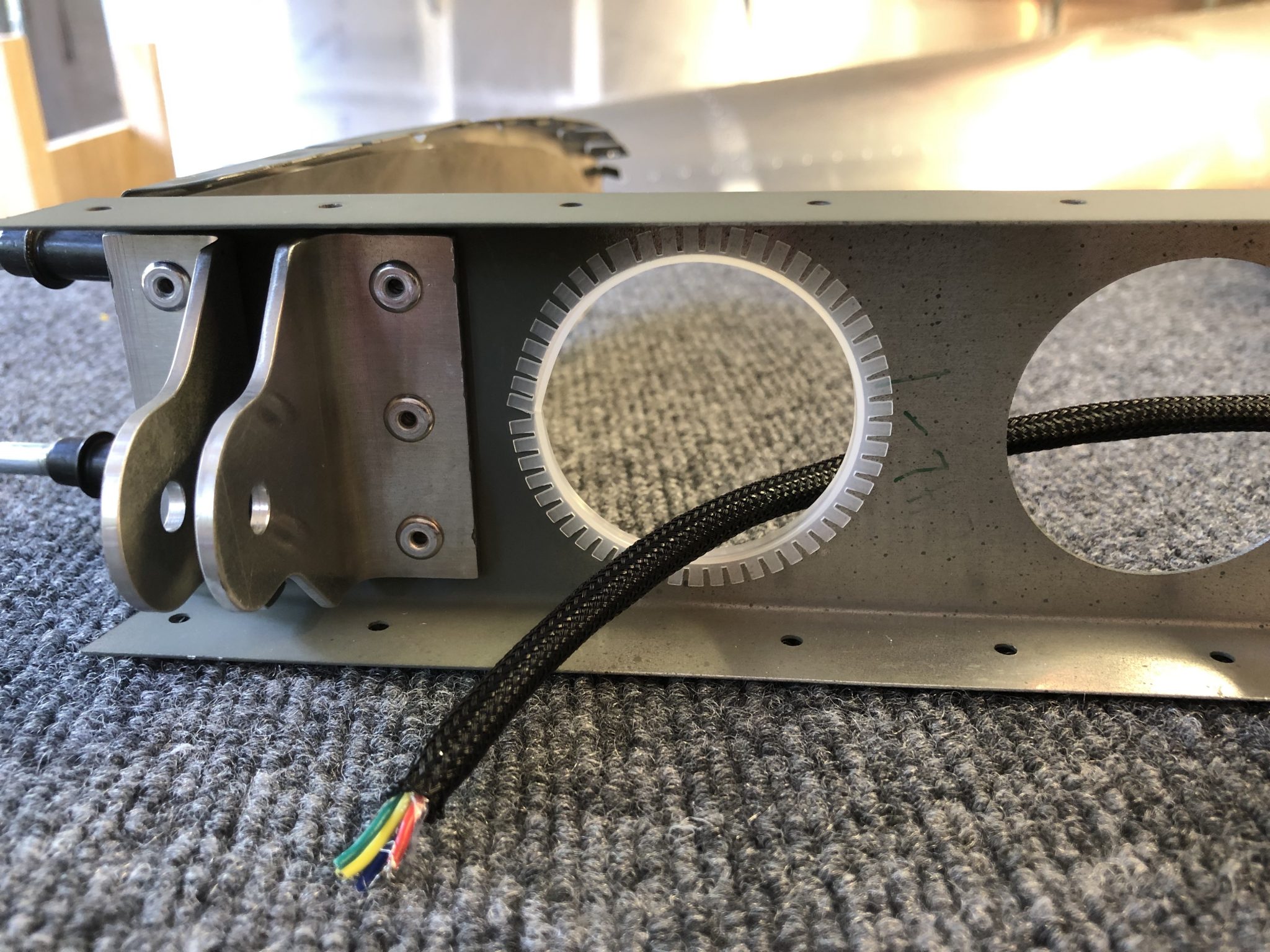
The last part was to create a connection from the regulator to wires I ran through the wings. I used some weatherpack connectors for this, which create a waterproof connection and a solid crimp, similar to the Delphi GT 150 that Midwest Panel uses to connect the wiring harness.
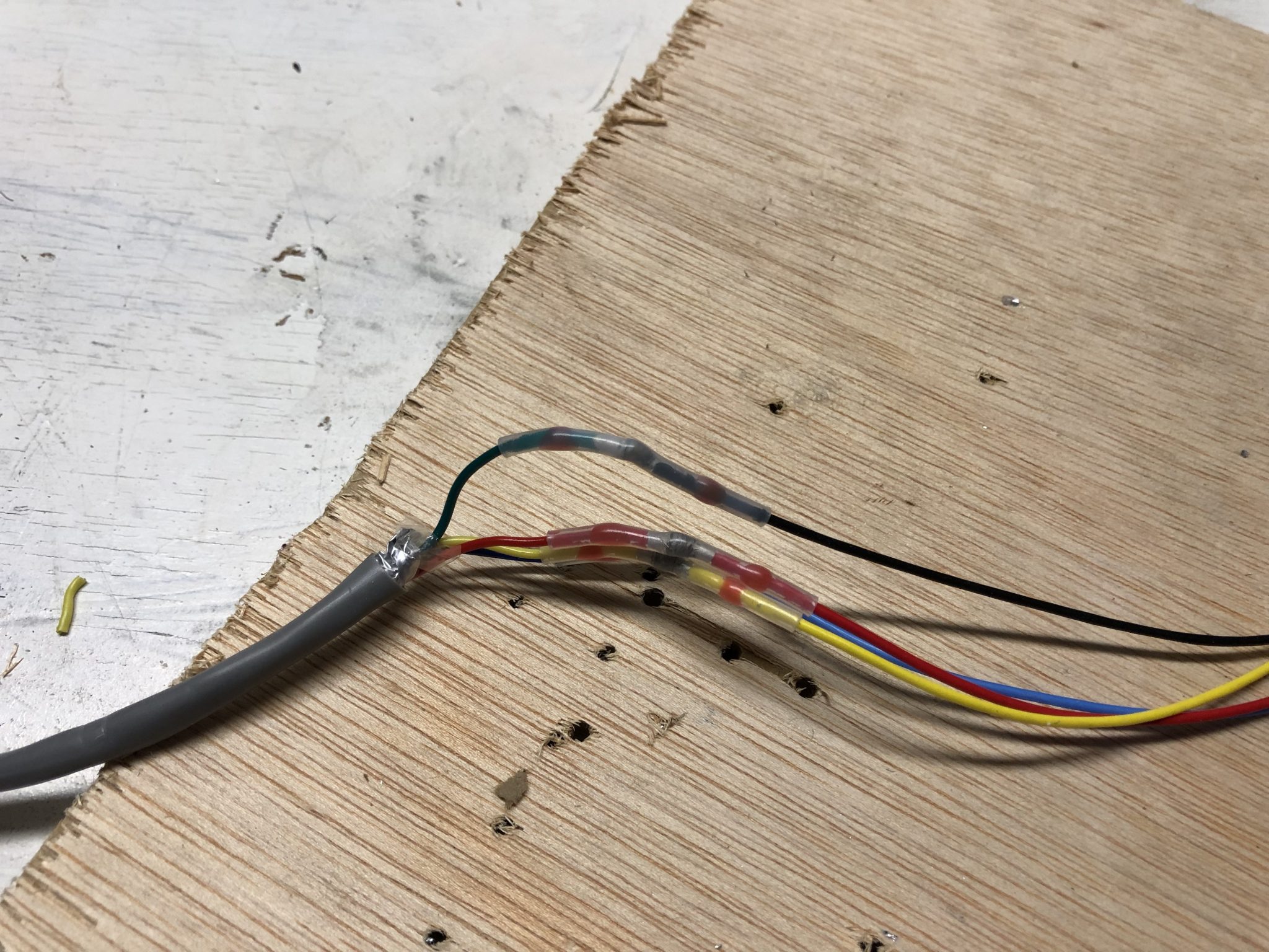
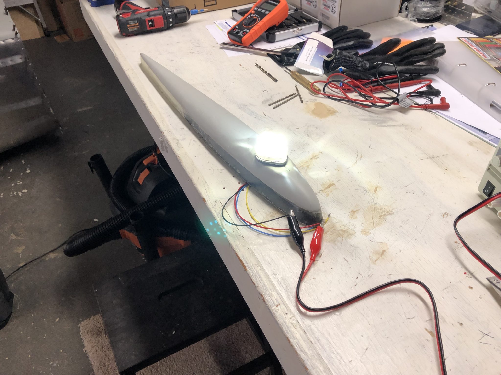
Final completed connection between the regular, the Pitot Tube and the wires running to the center.
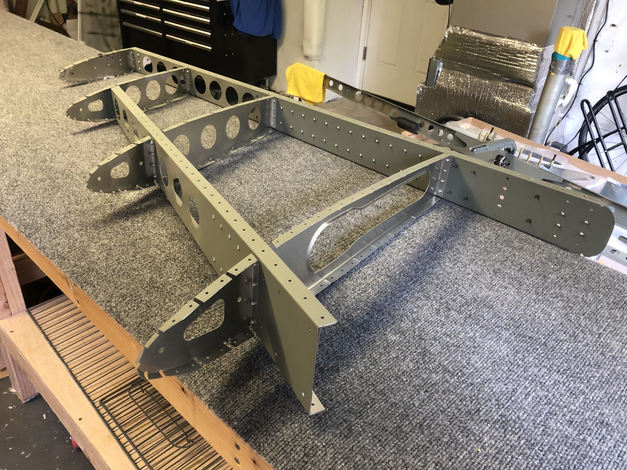
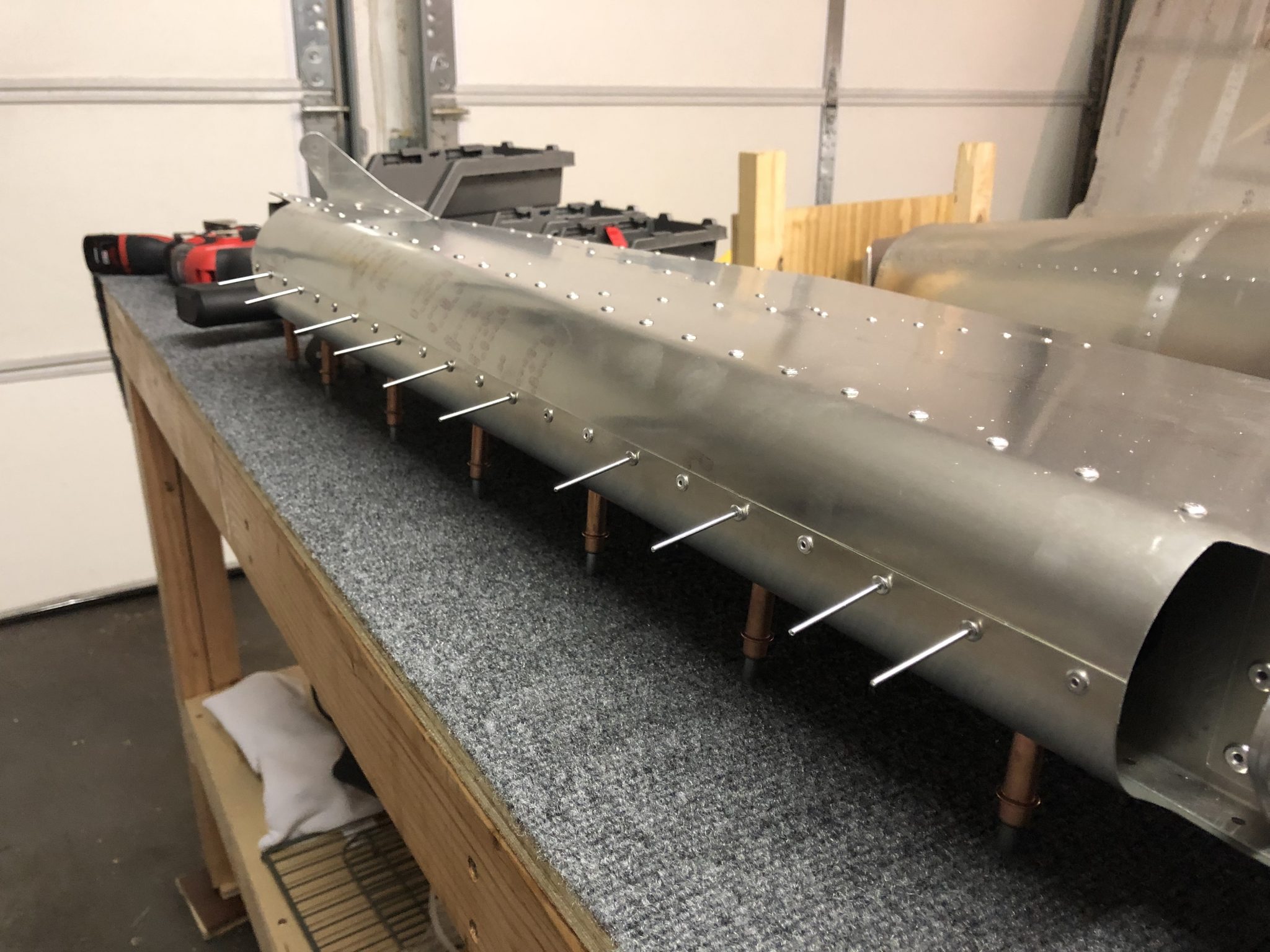
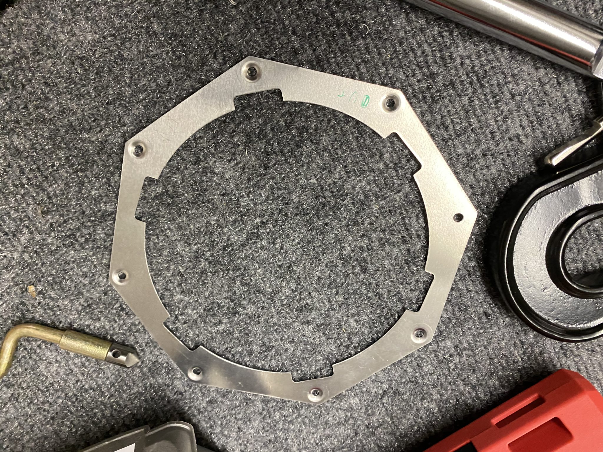
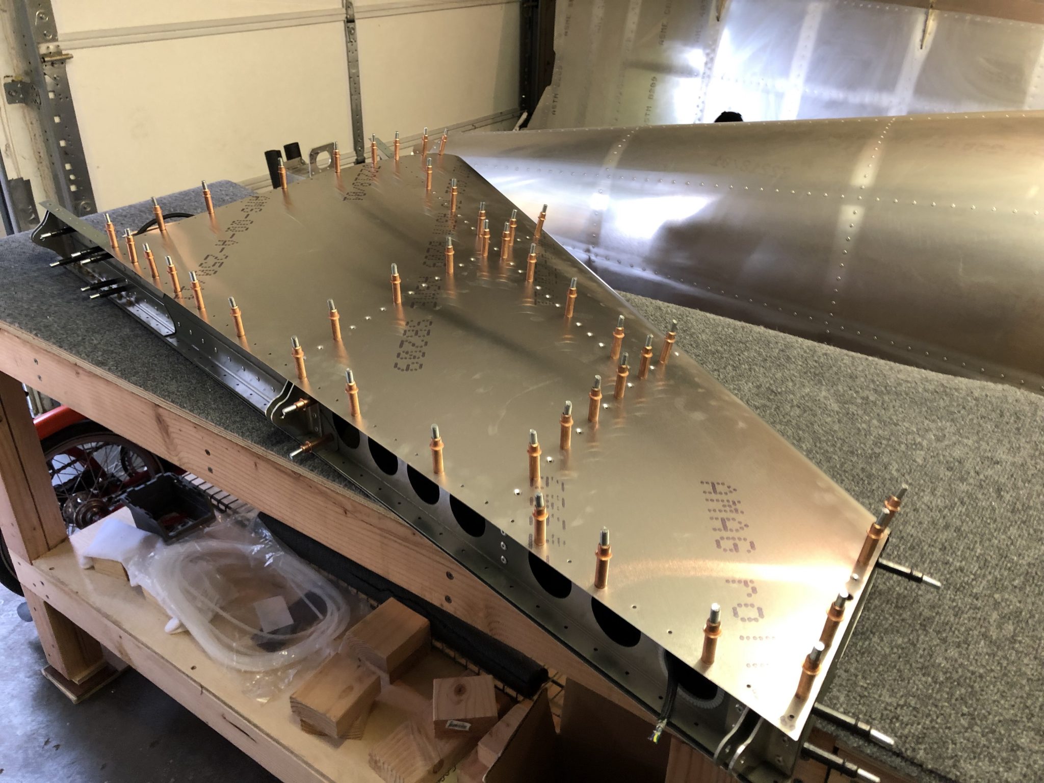
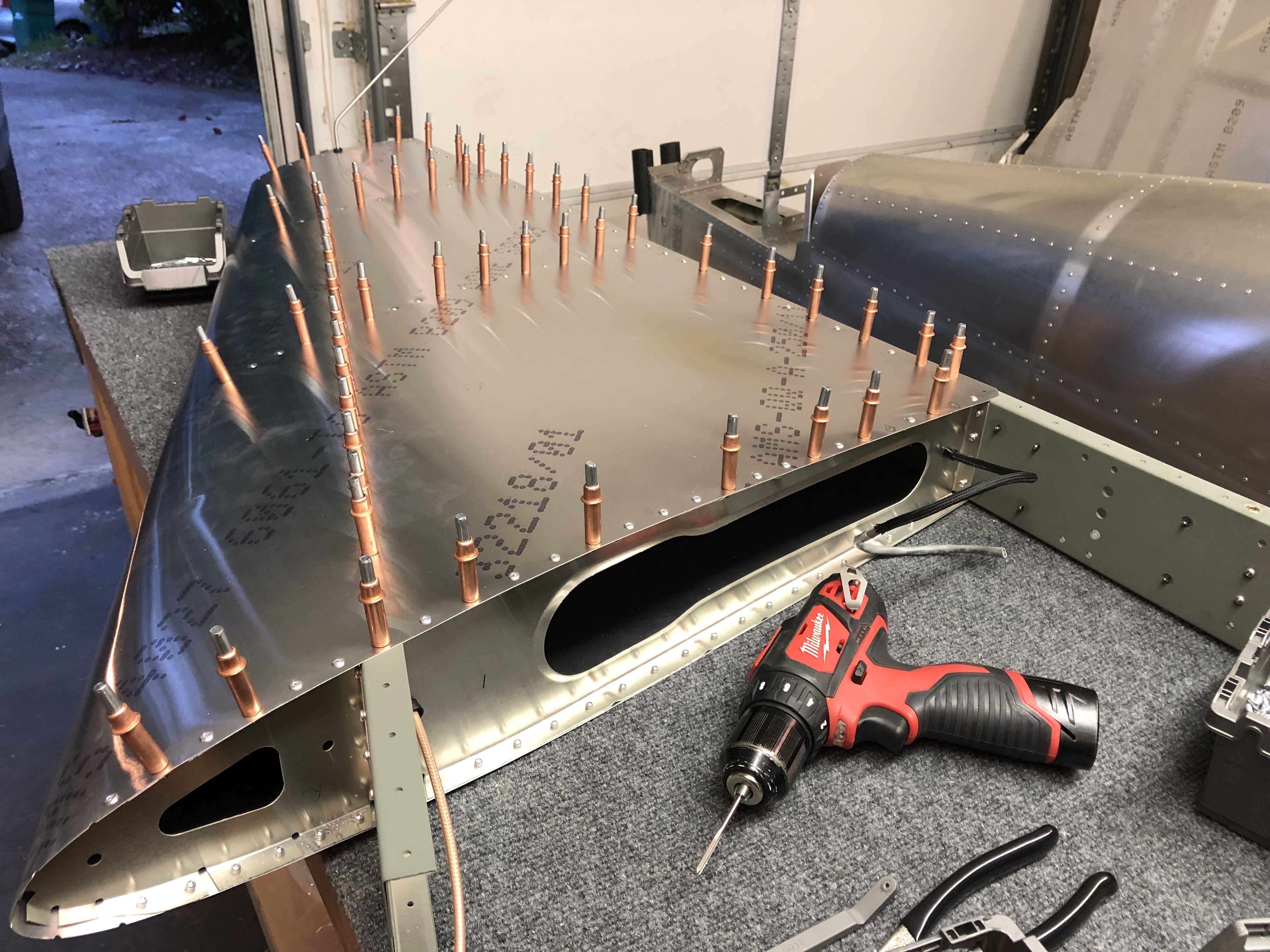
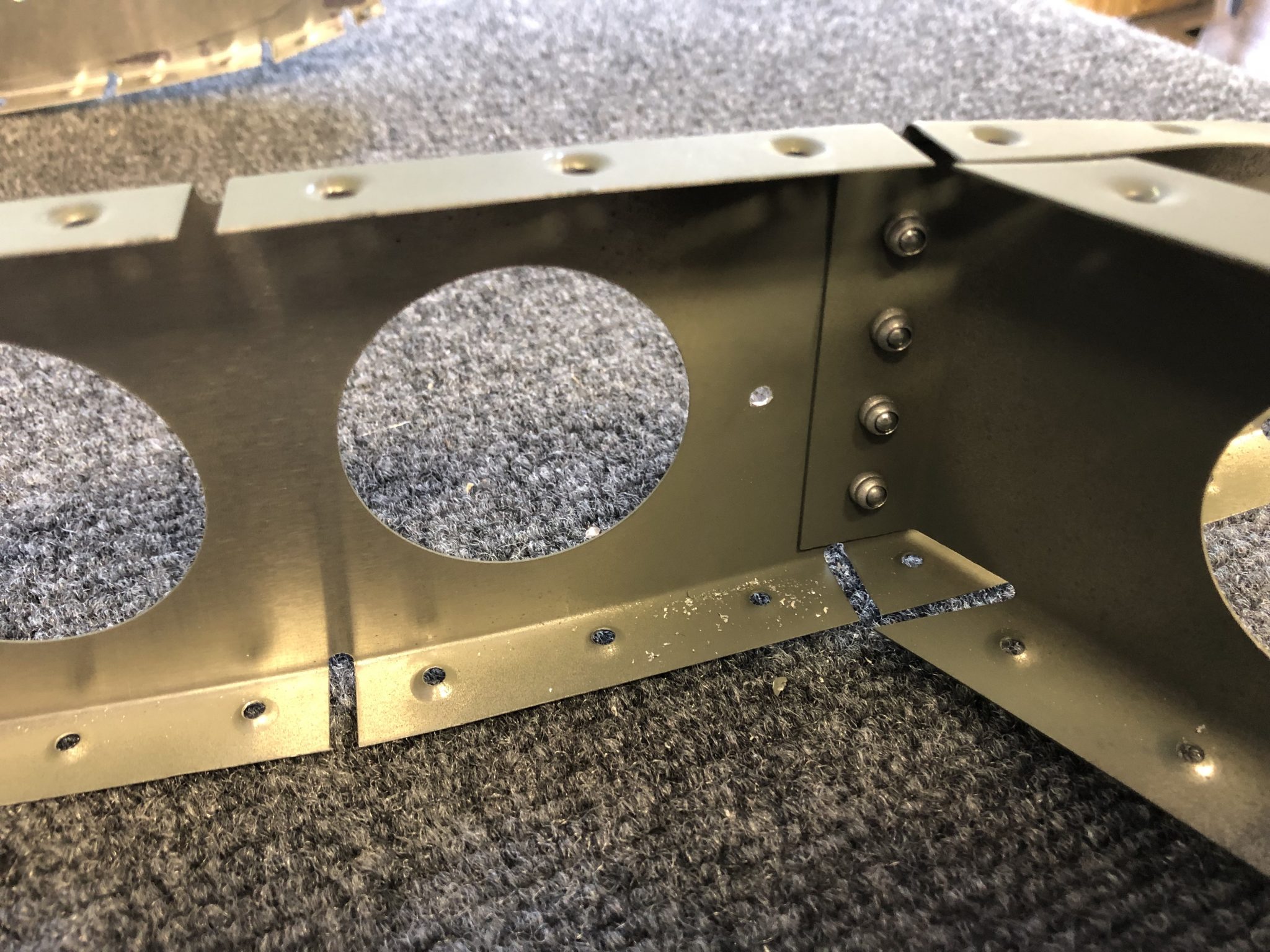
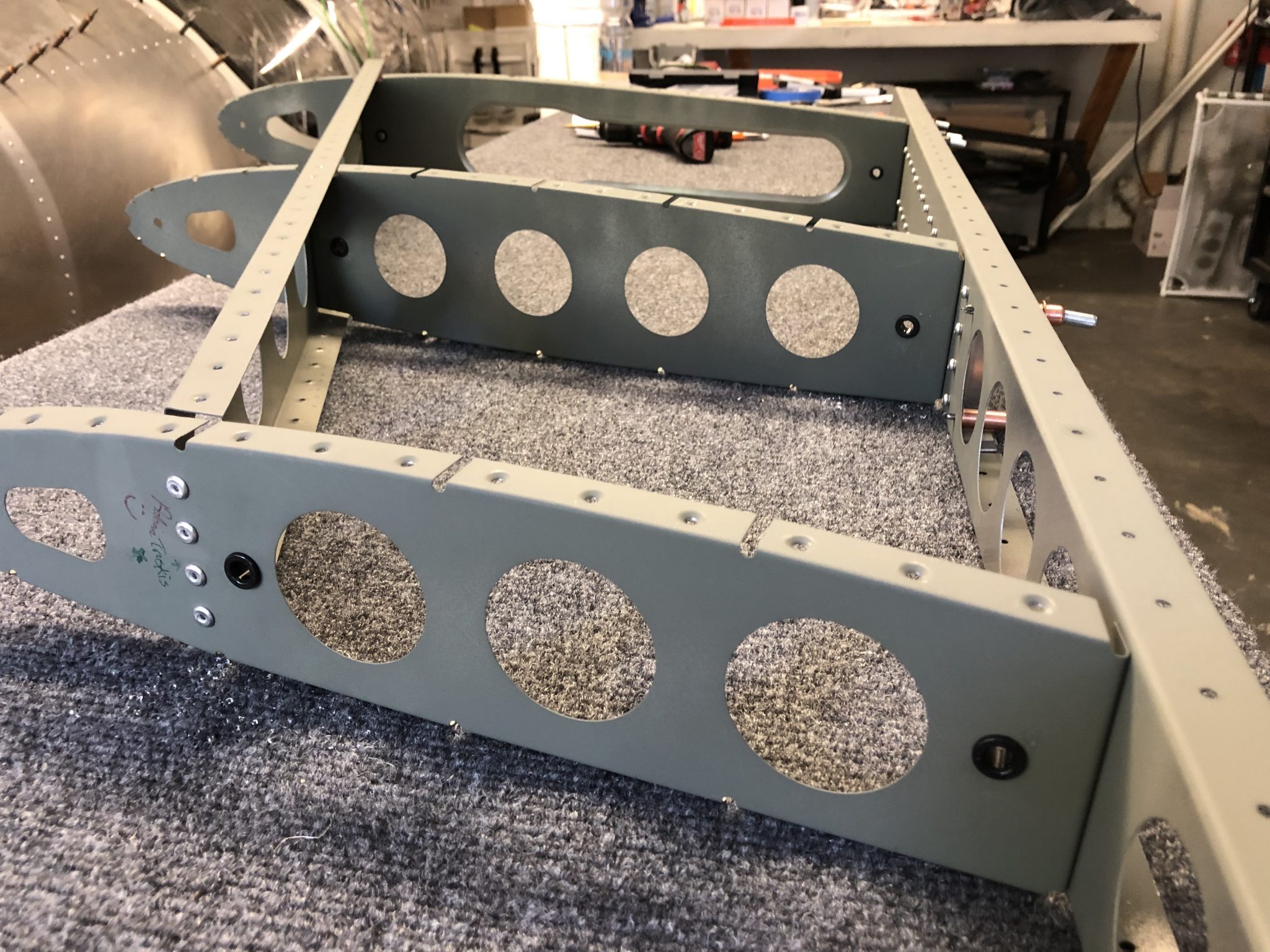
Installing the plate to the wing
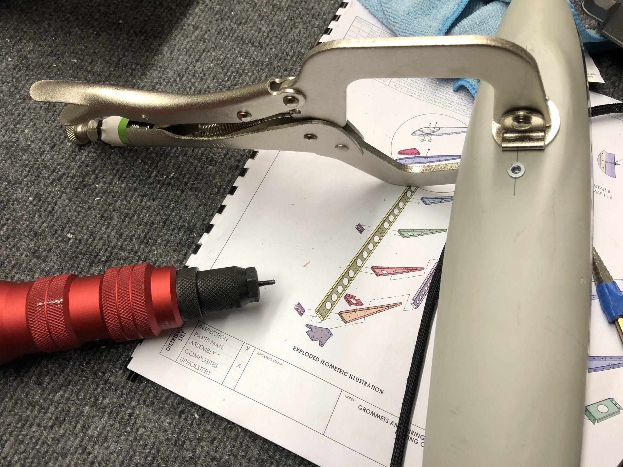
The last and final part of the installation was to mount the inspection panel plate onto the wing. I did this last to prevent scraping up my arm while I had to do all the mounting inside the wing, since the backing plate that holds the plate in place has a series of pokey corners that love to eat airplane builder blood.
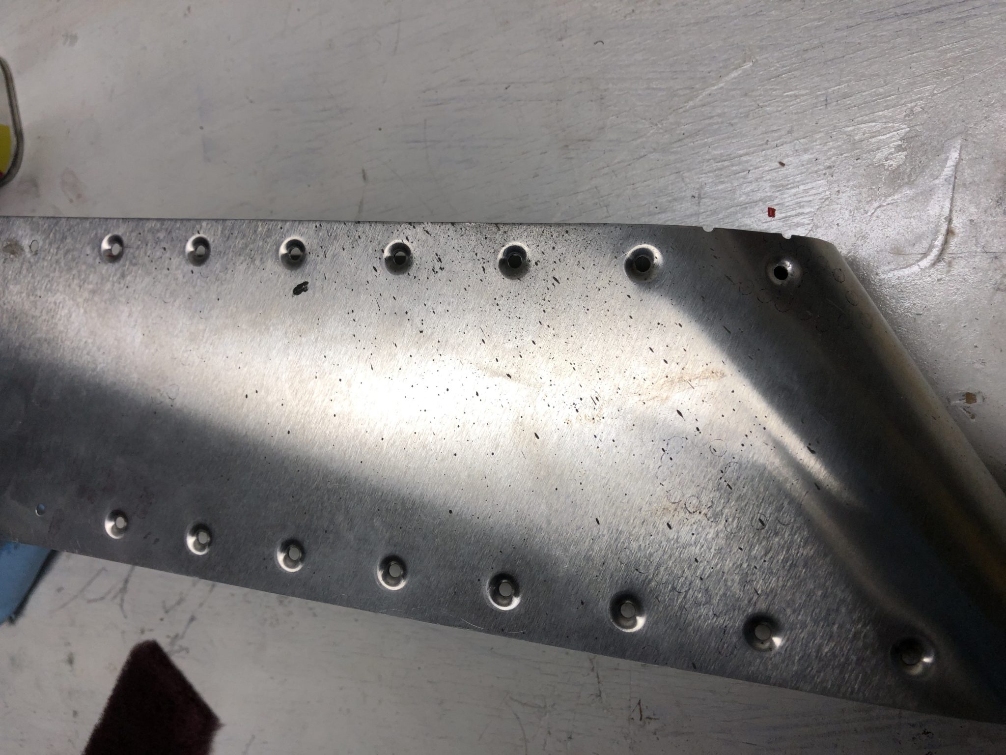
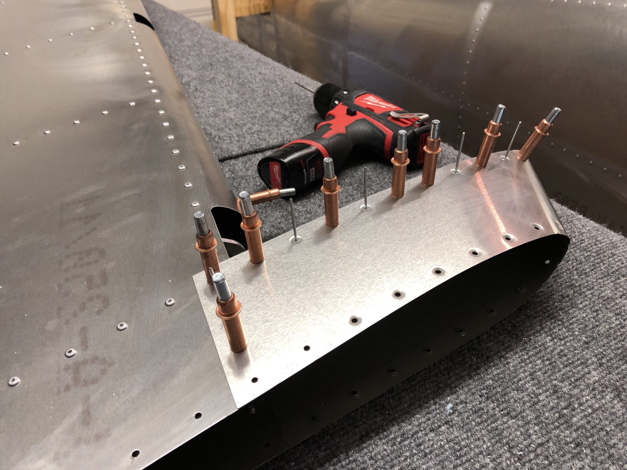
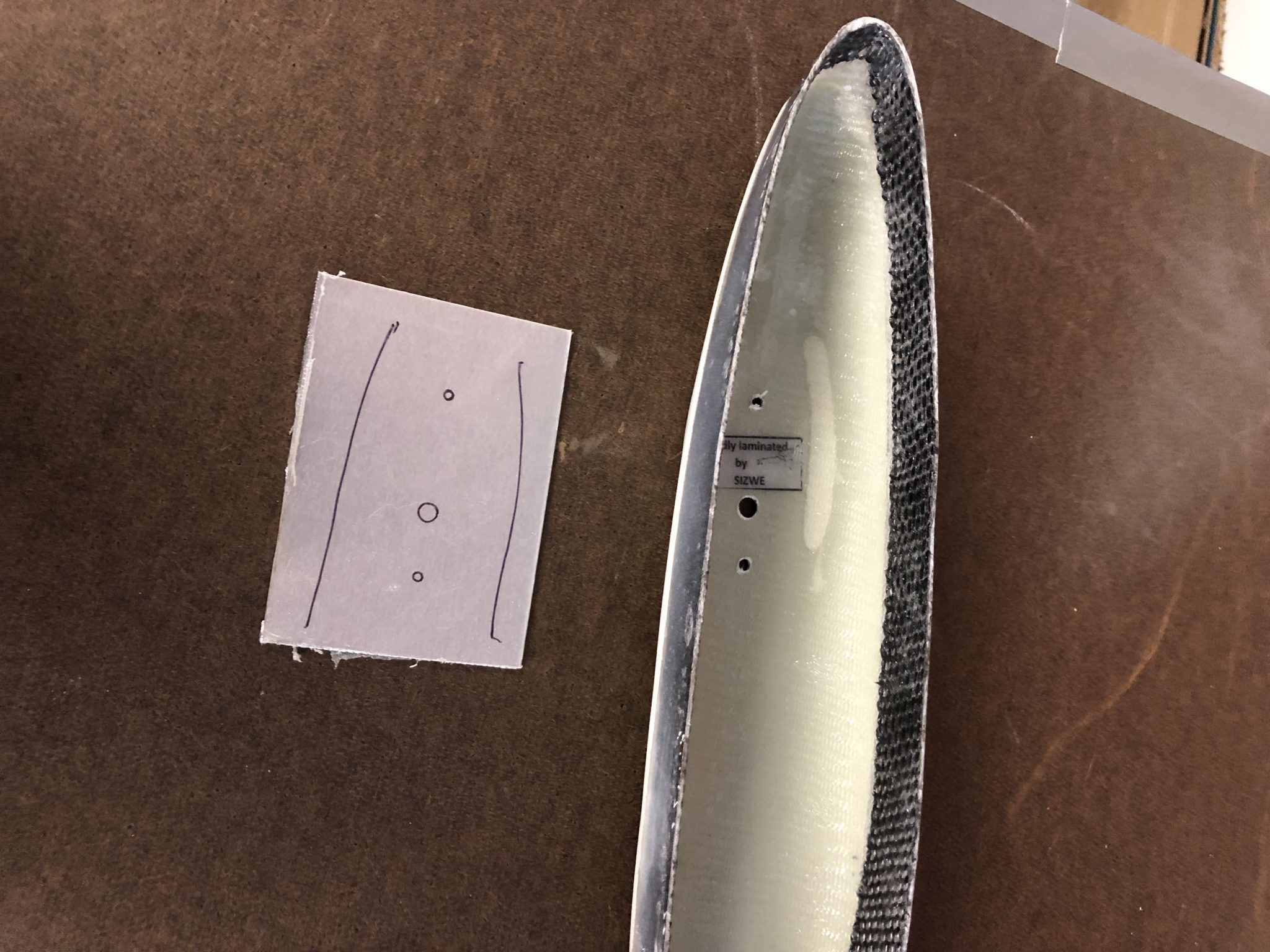
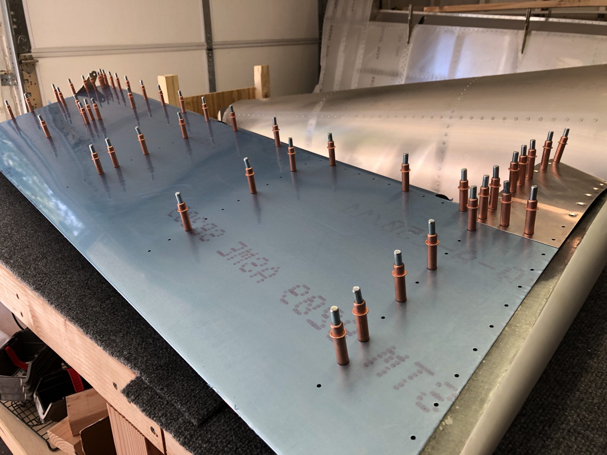
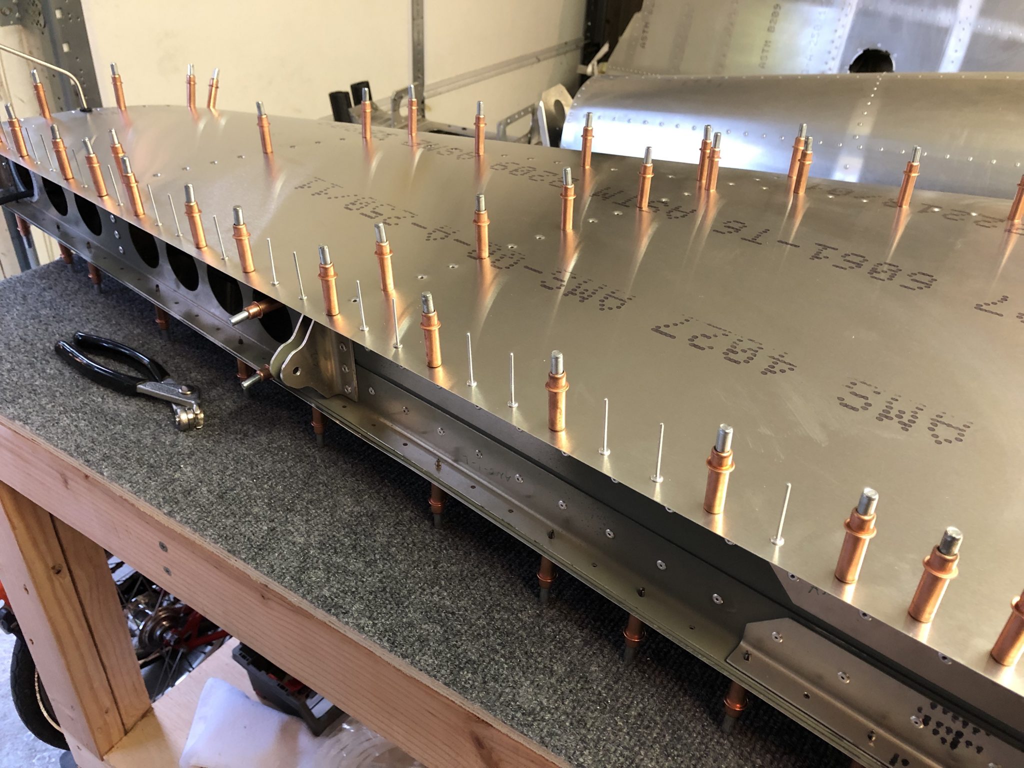
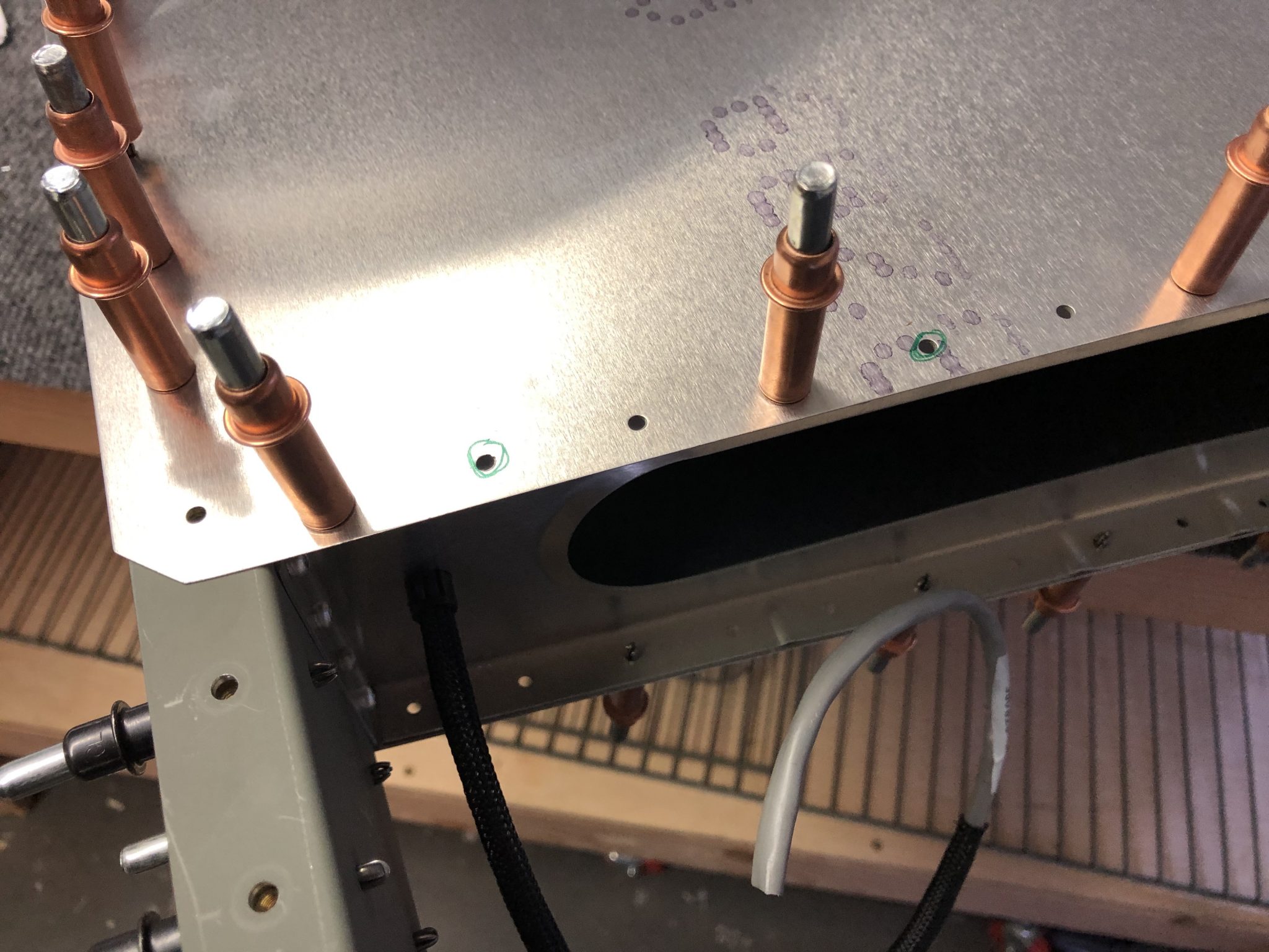
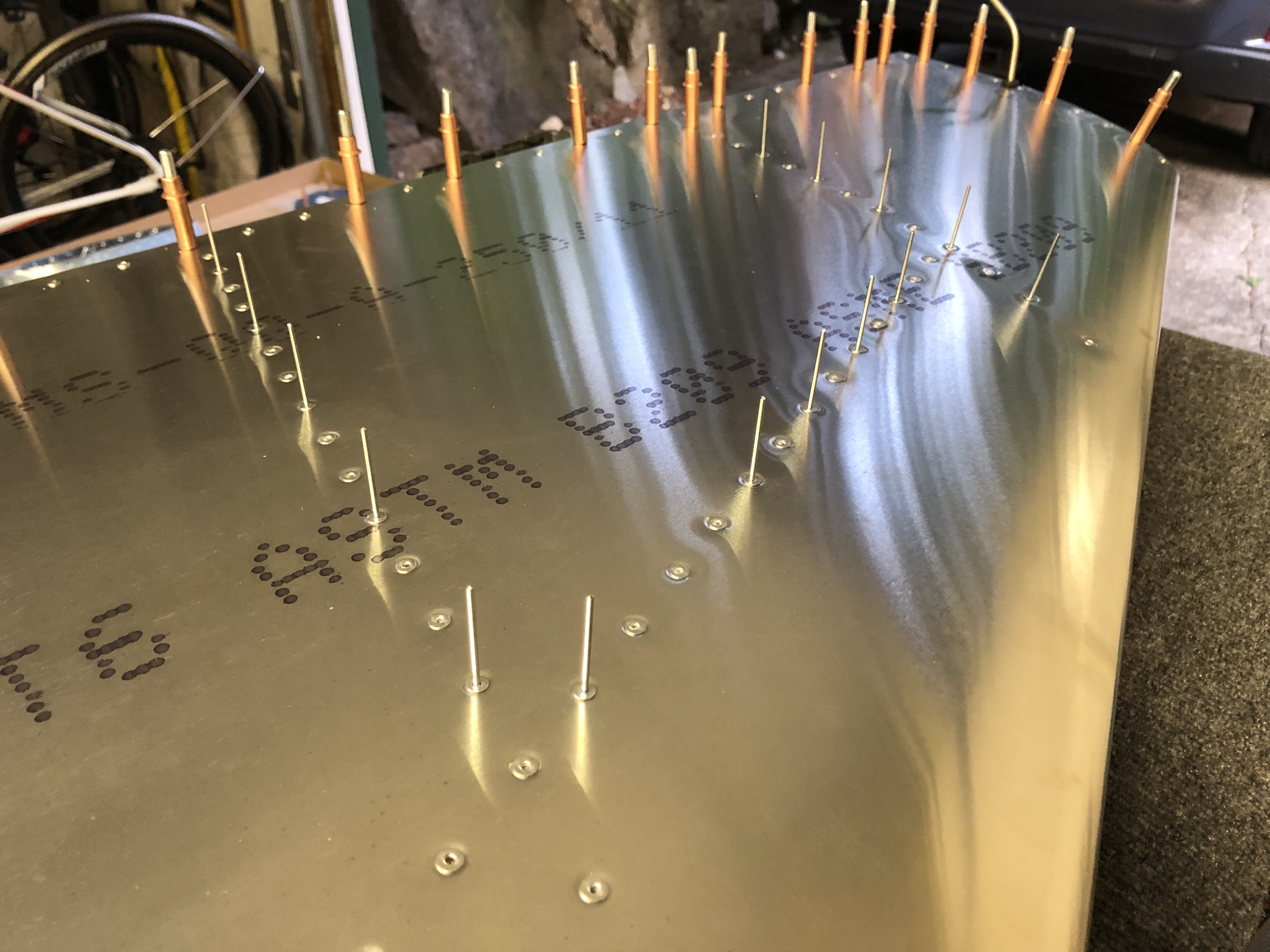
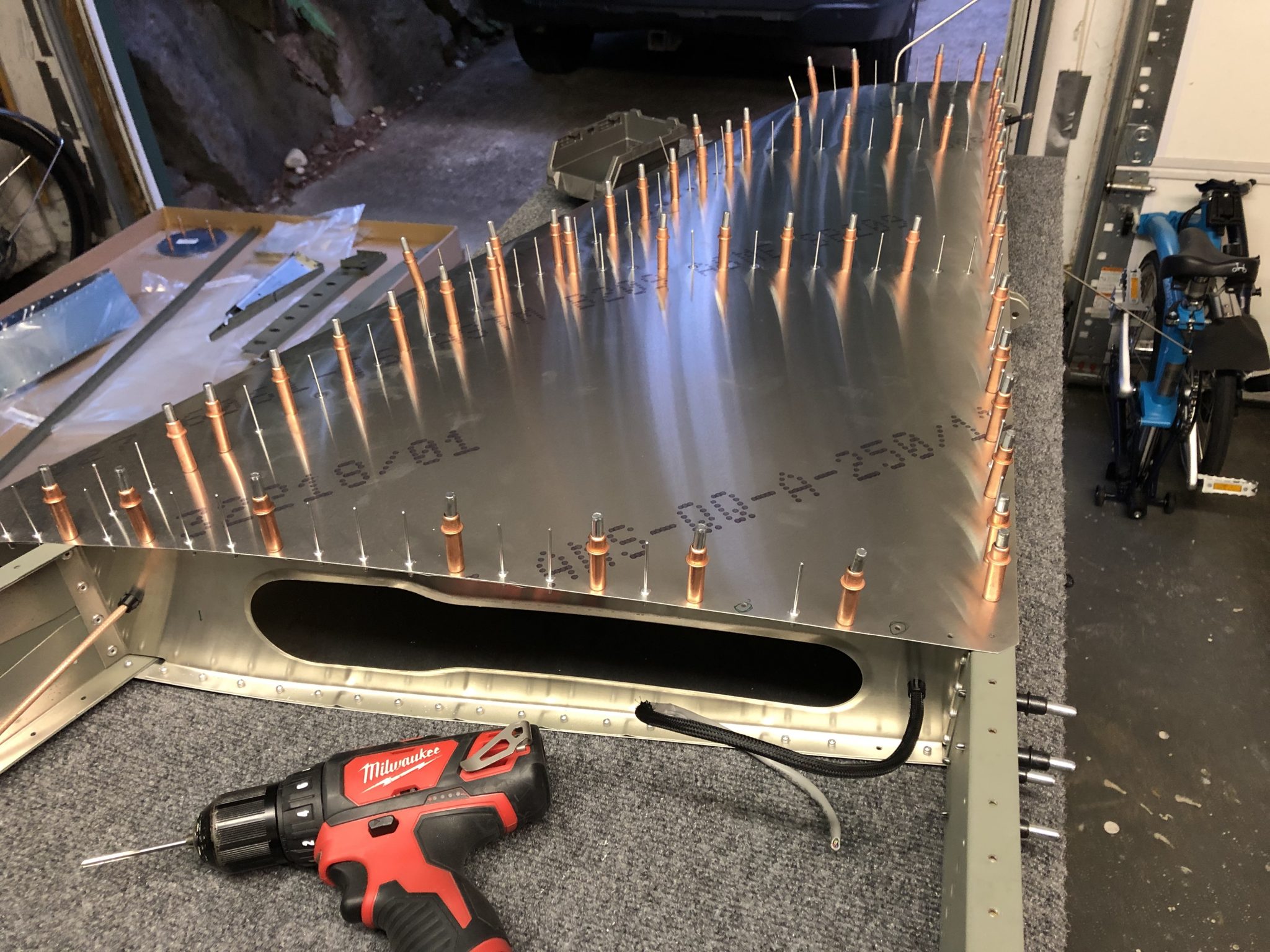
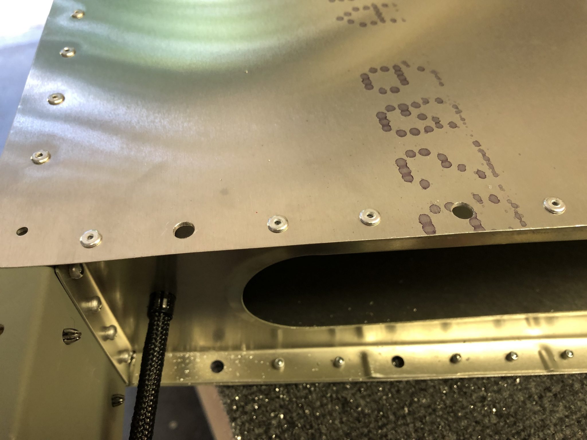
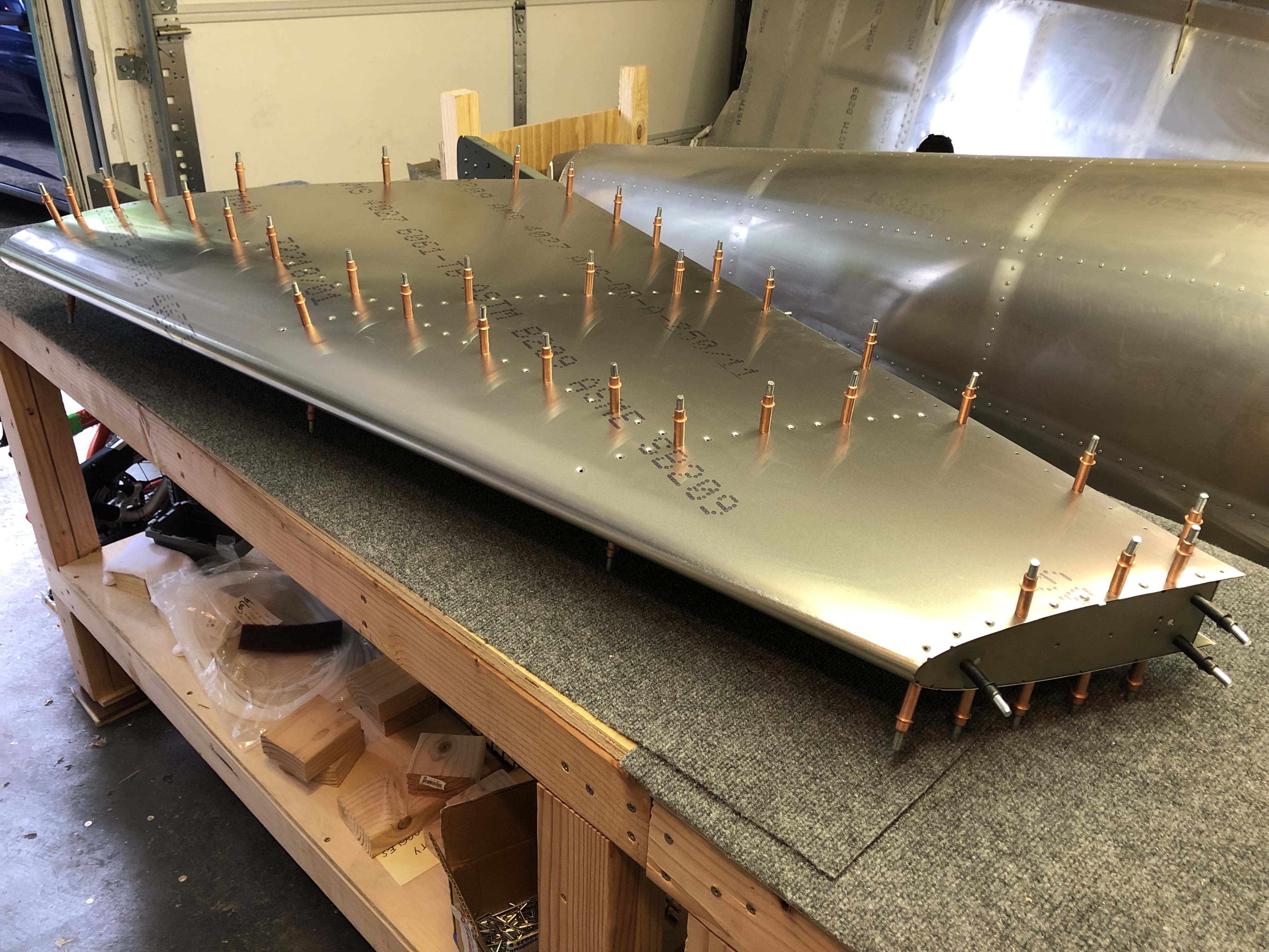
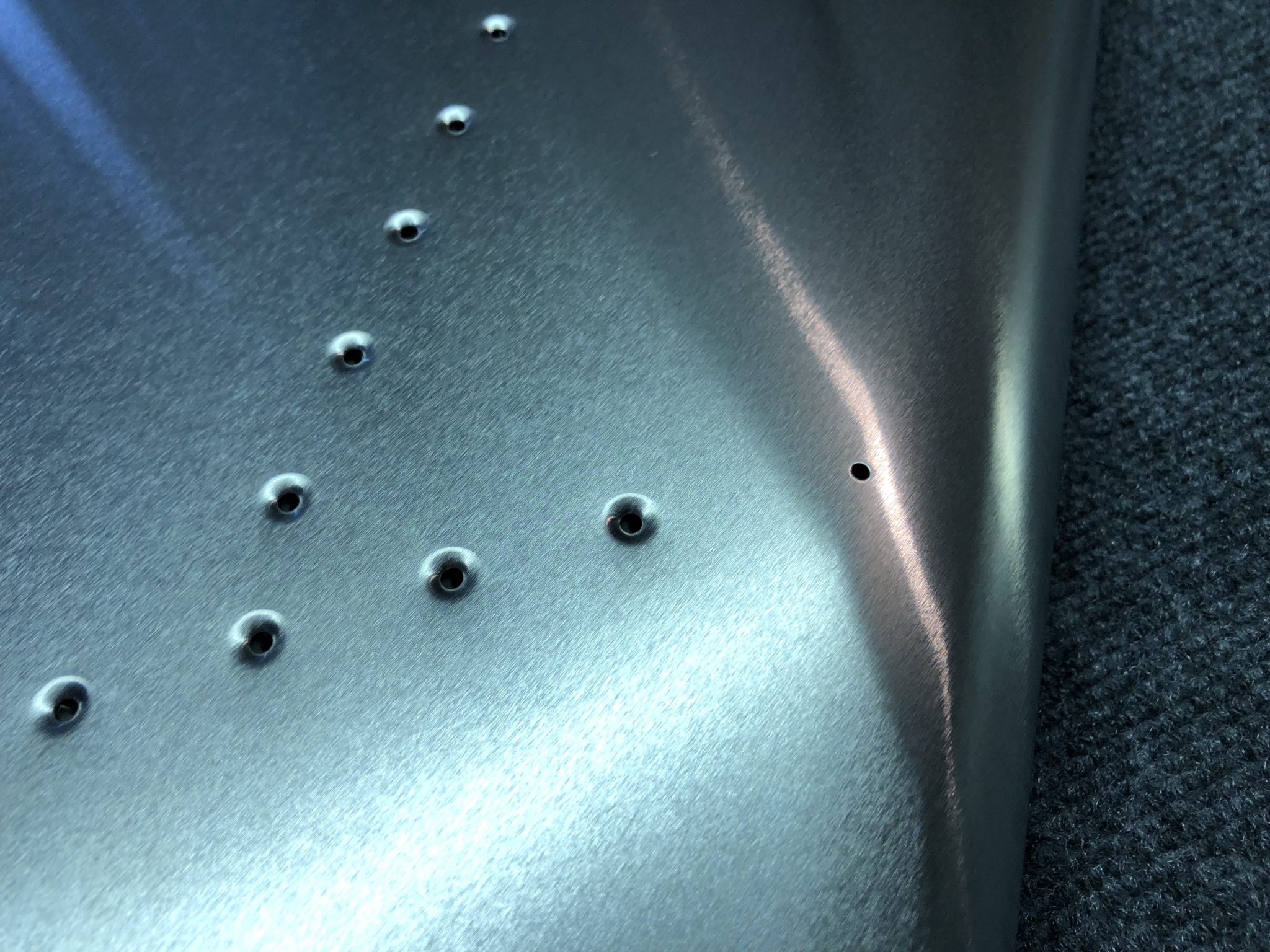
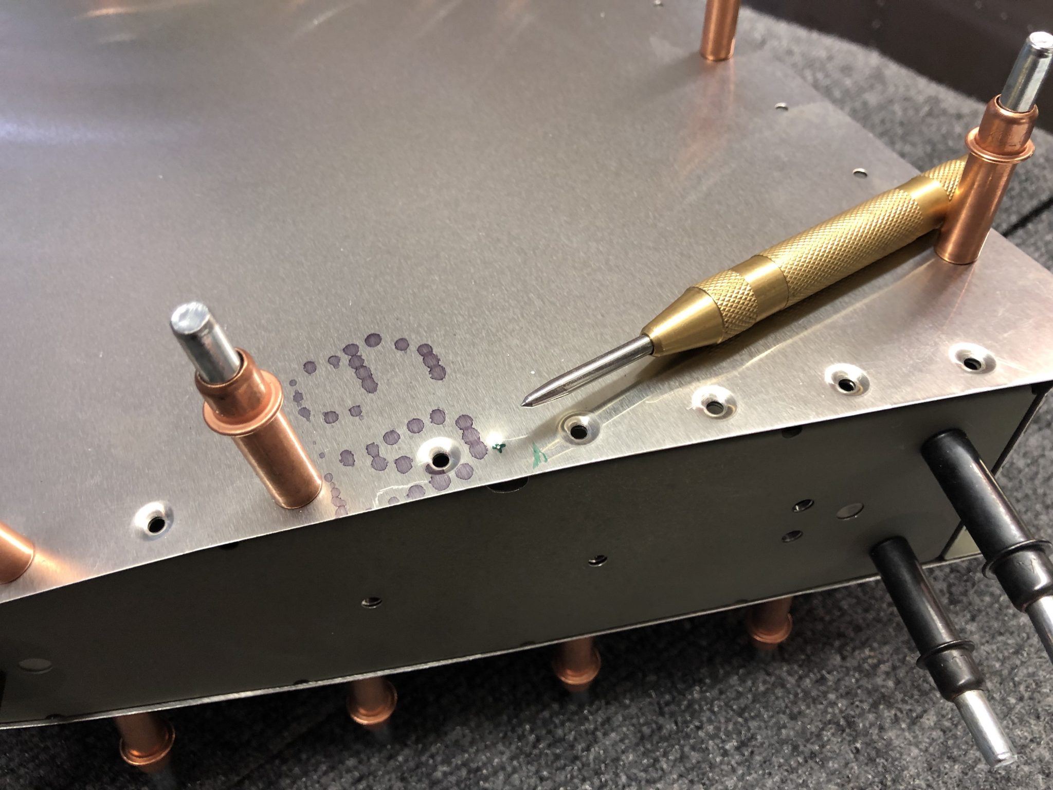
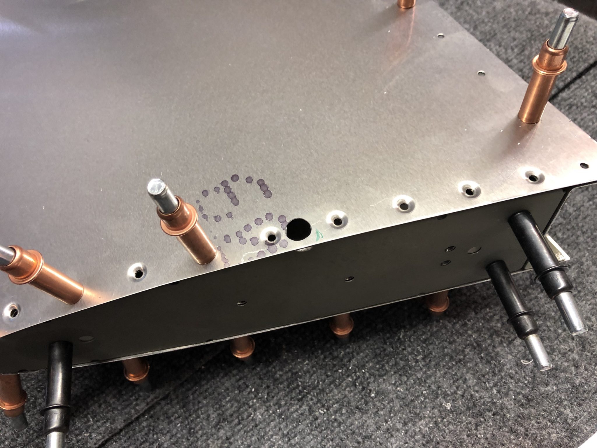
First I lined up the plate with the wing and then did the match drilling of the holes:
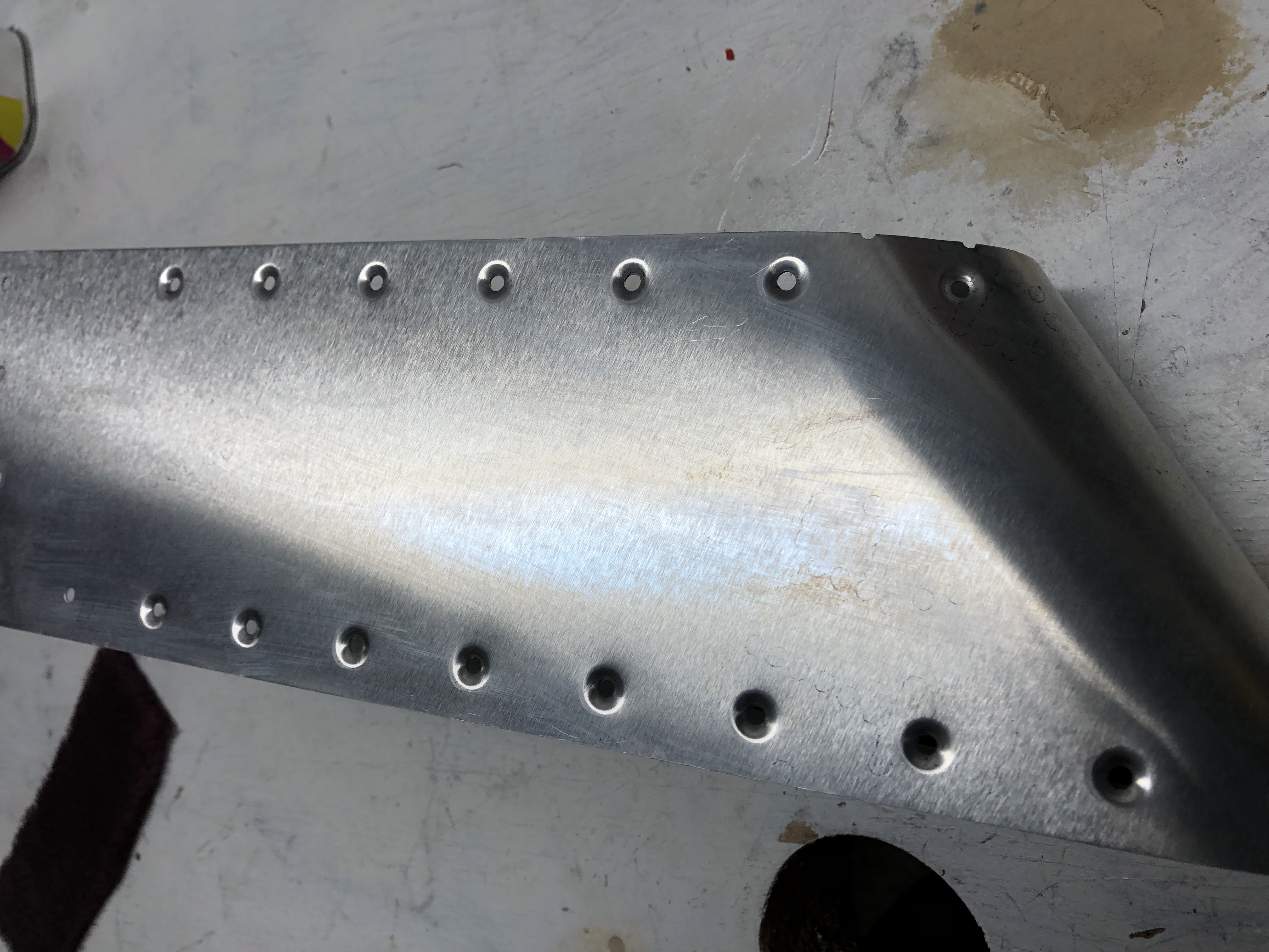
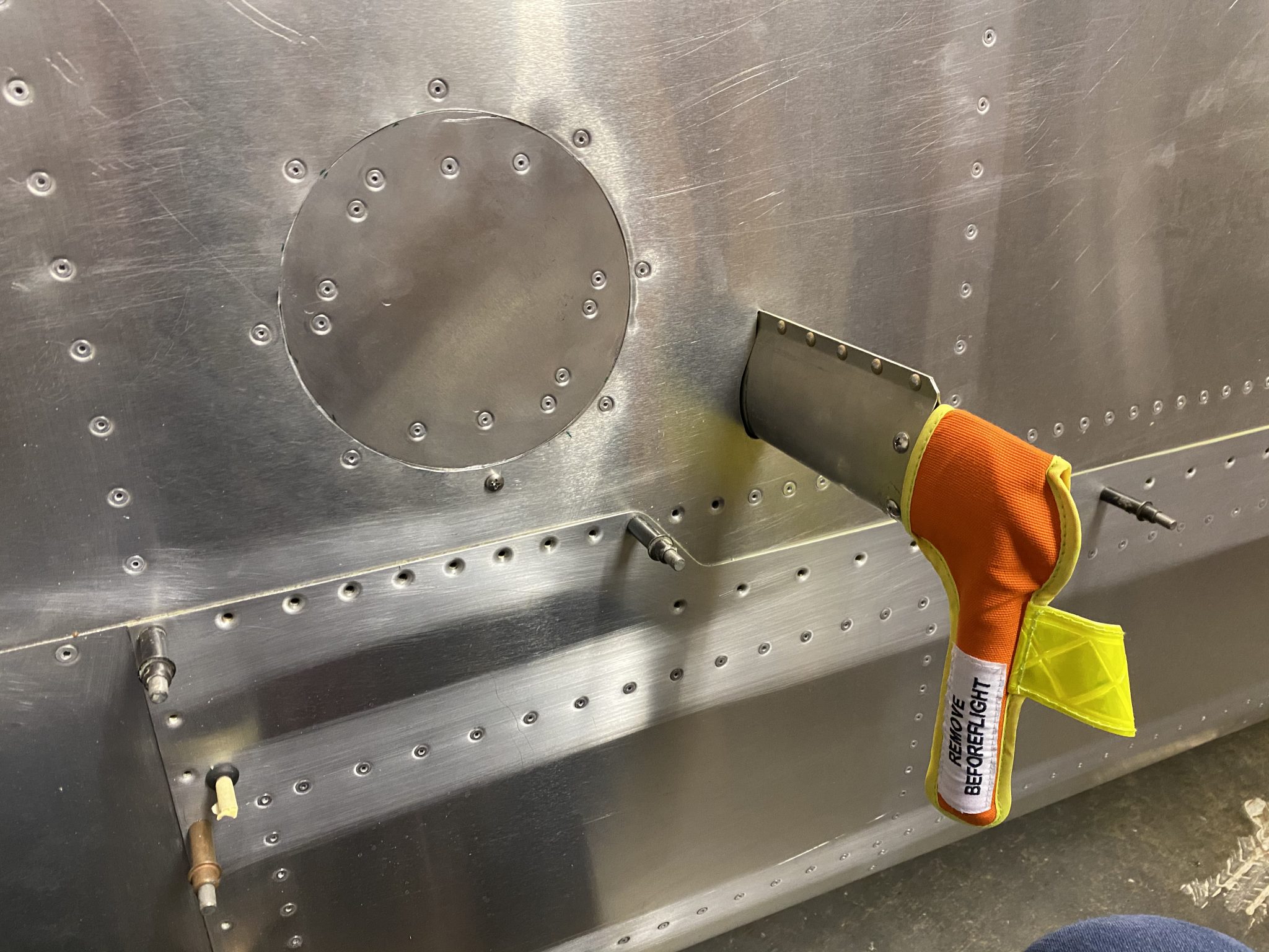
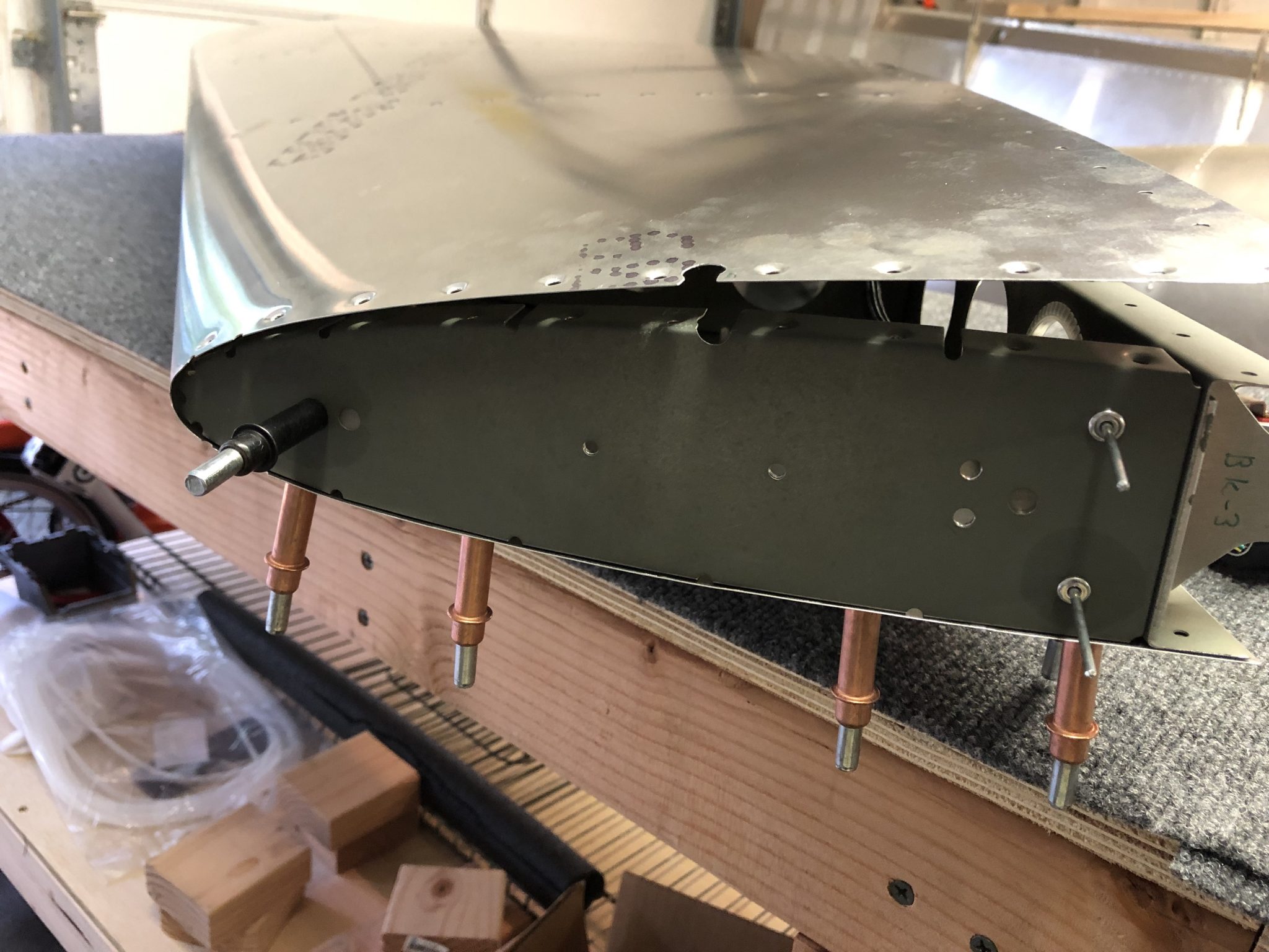
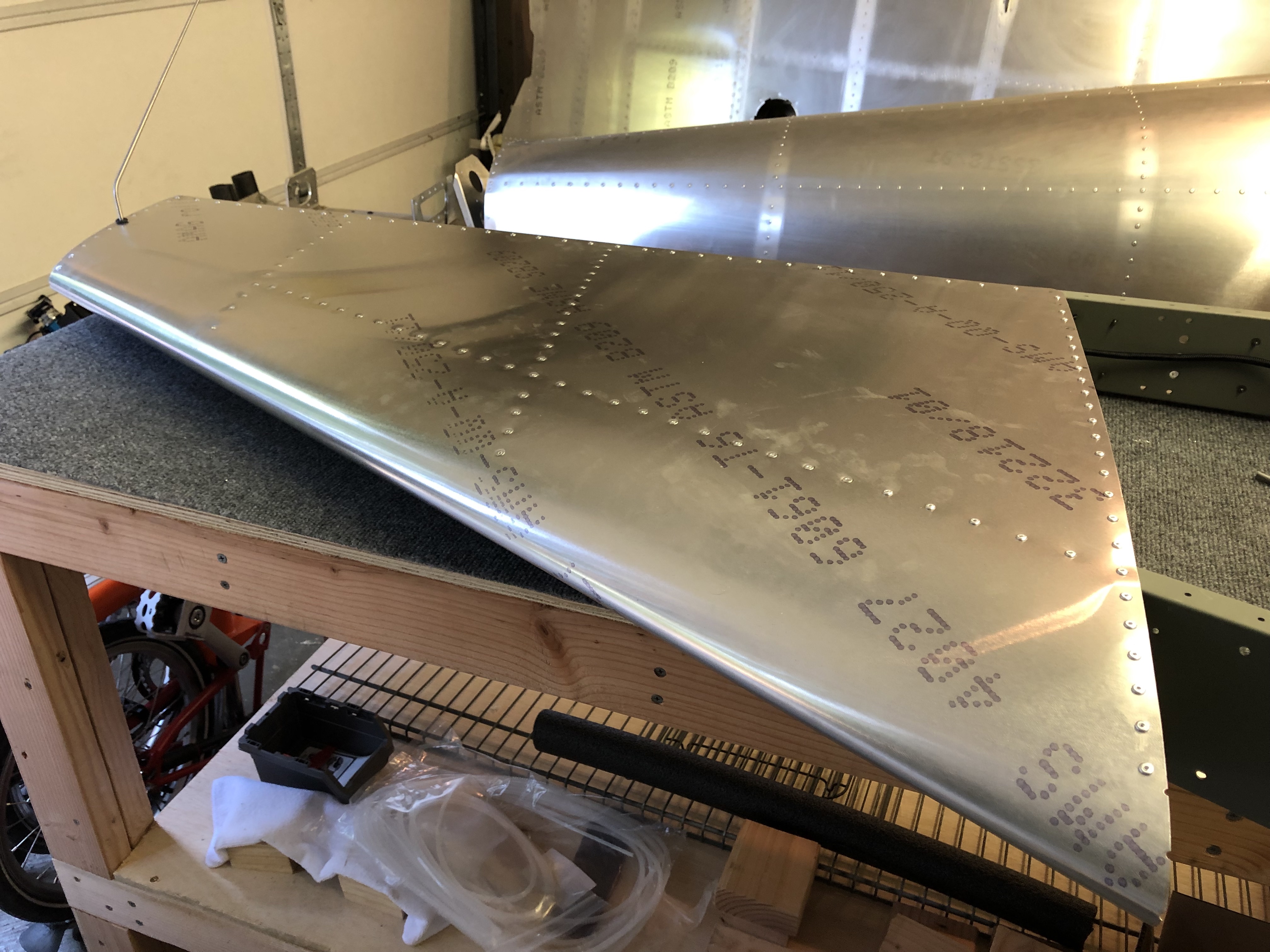
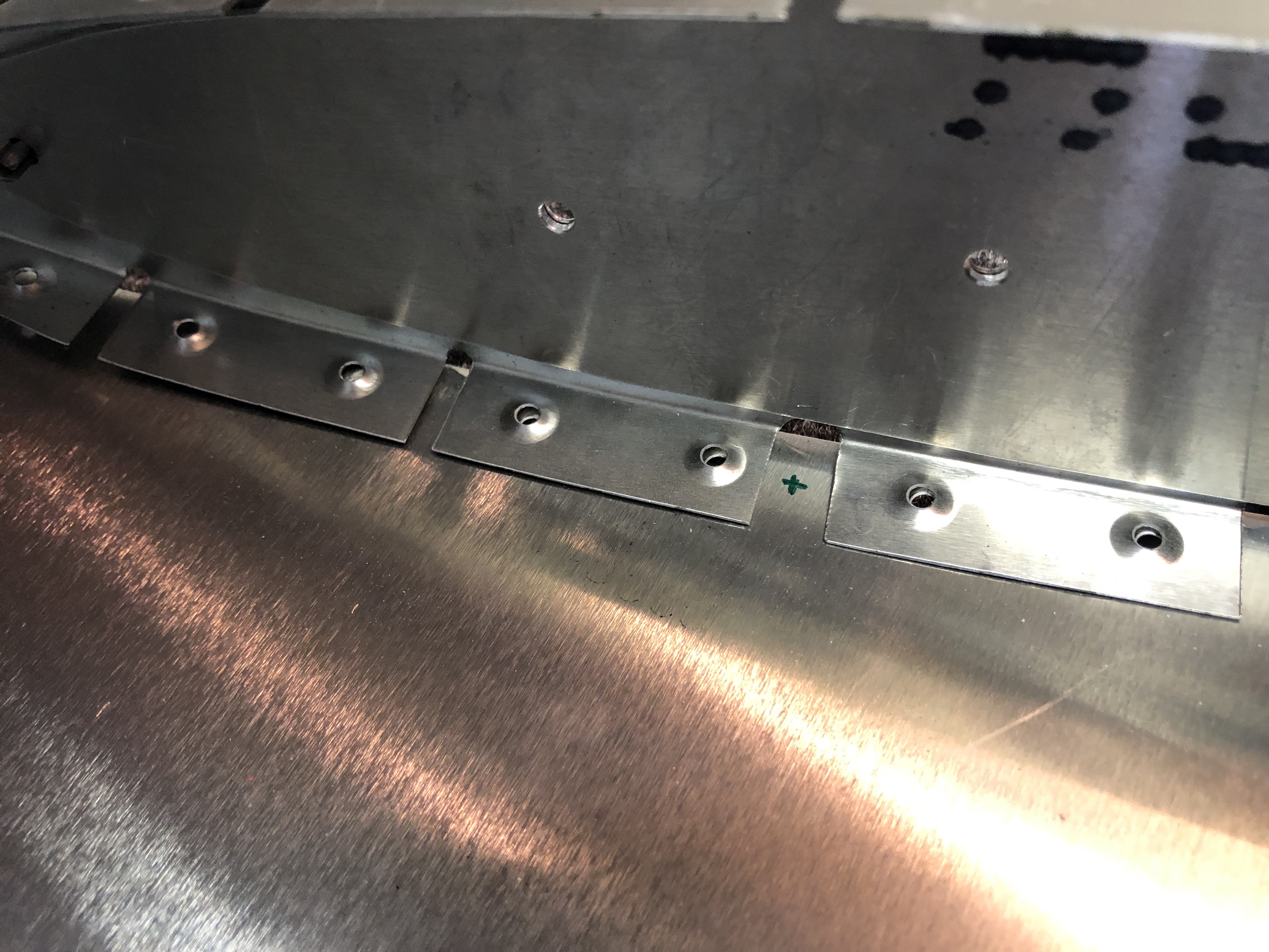
The I dimpled the plate and the matching holes on the wing and riveted it in place.
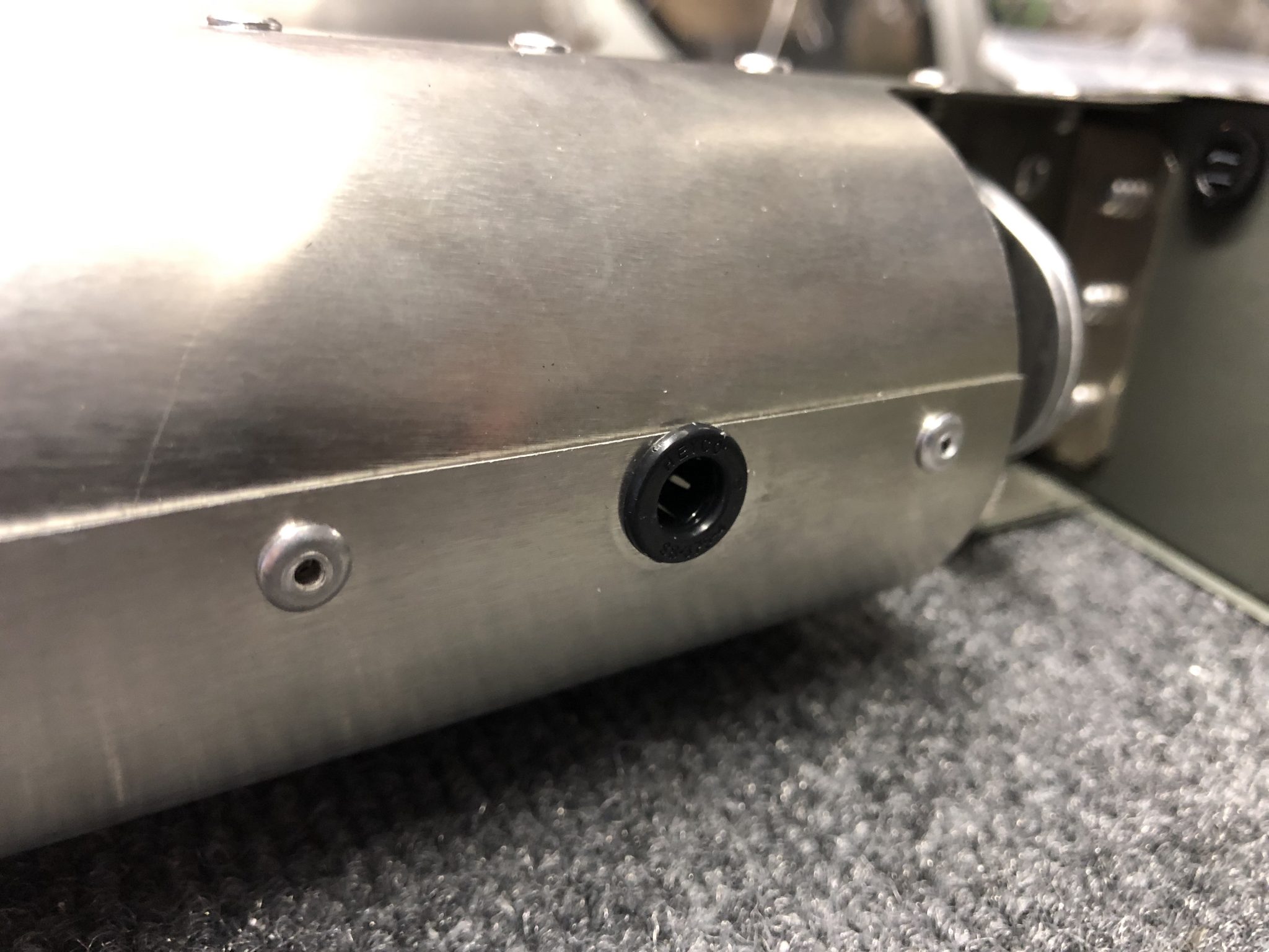
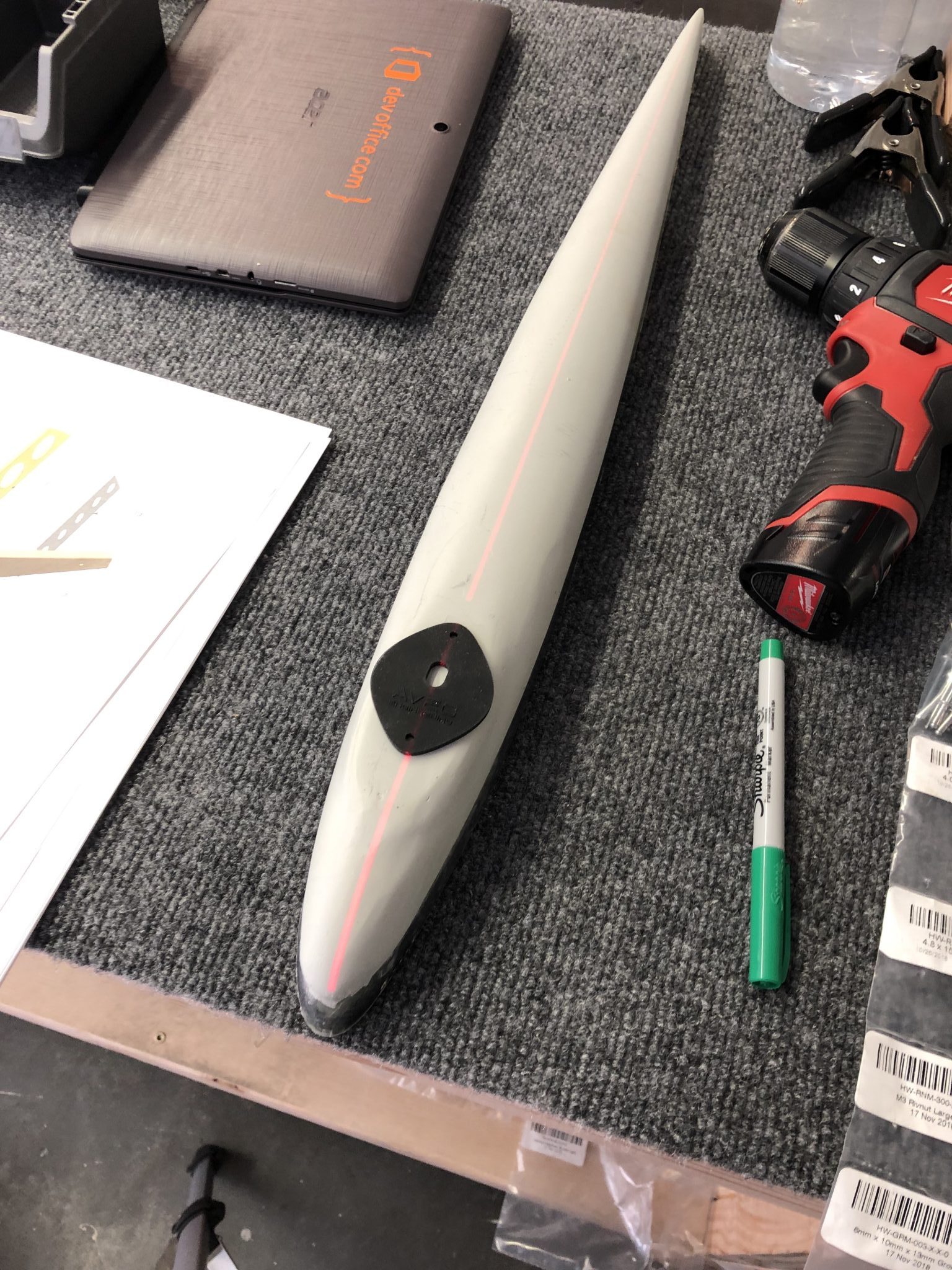
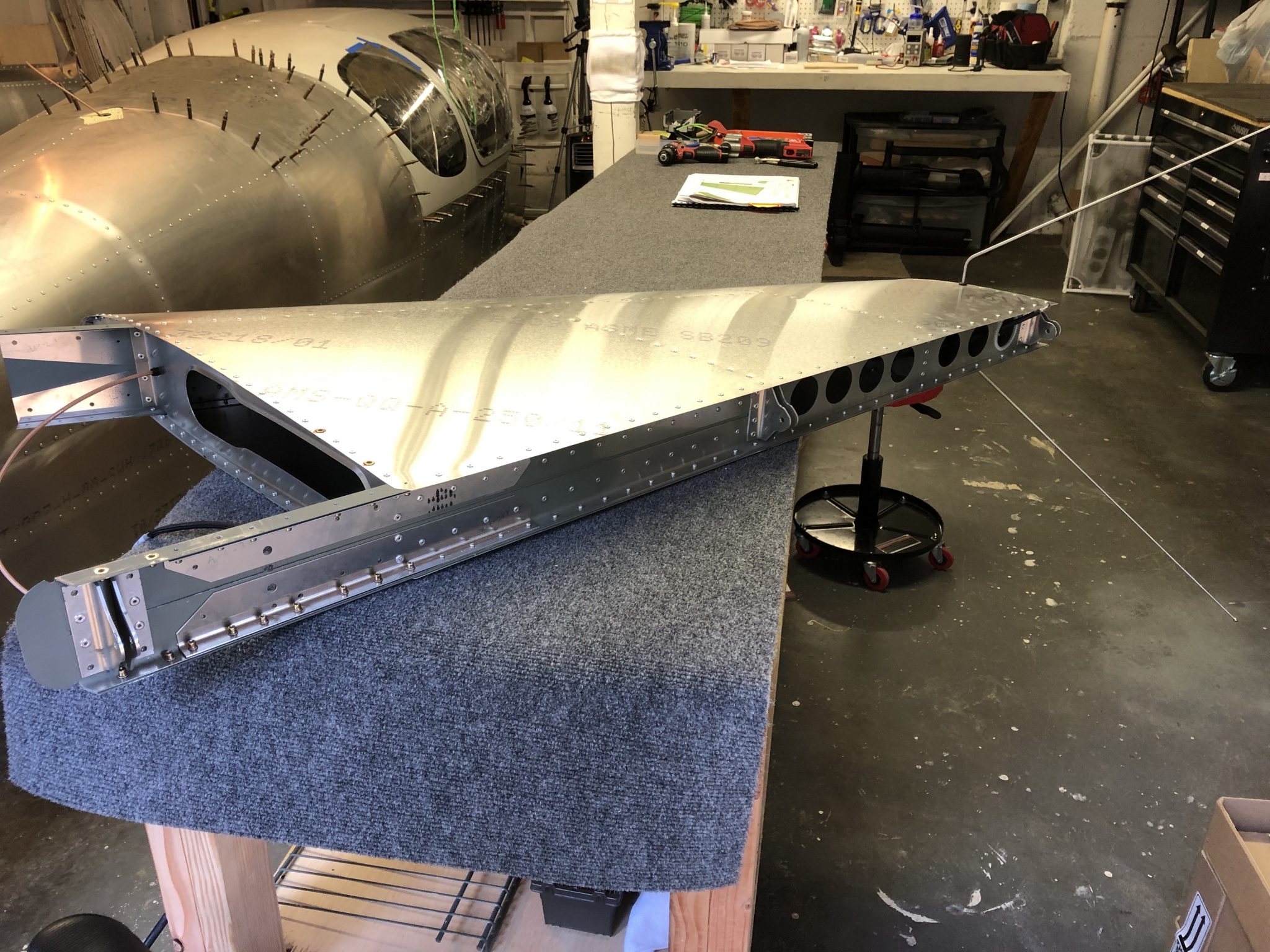
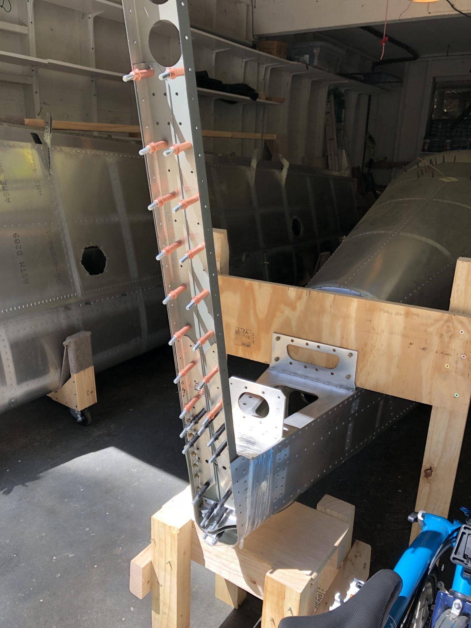
And here is the completed and closed up Pitot Tube and Inspection Plate that holds the regulator:


 ,
,