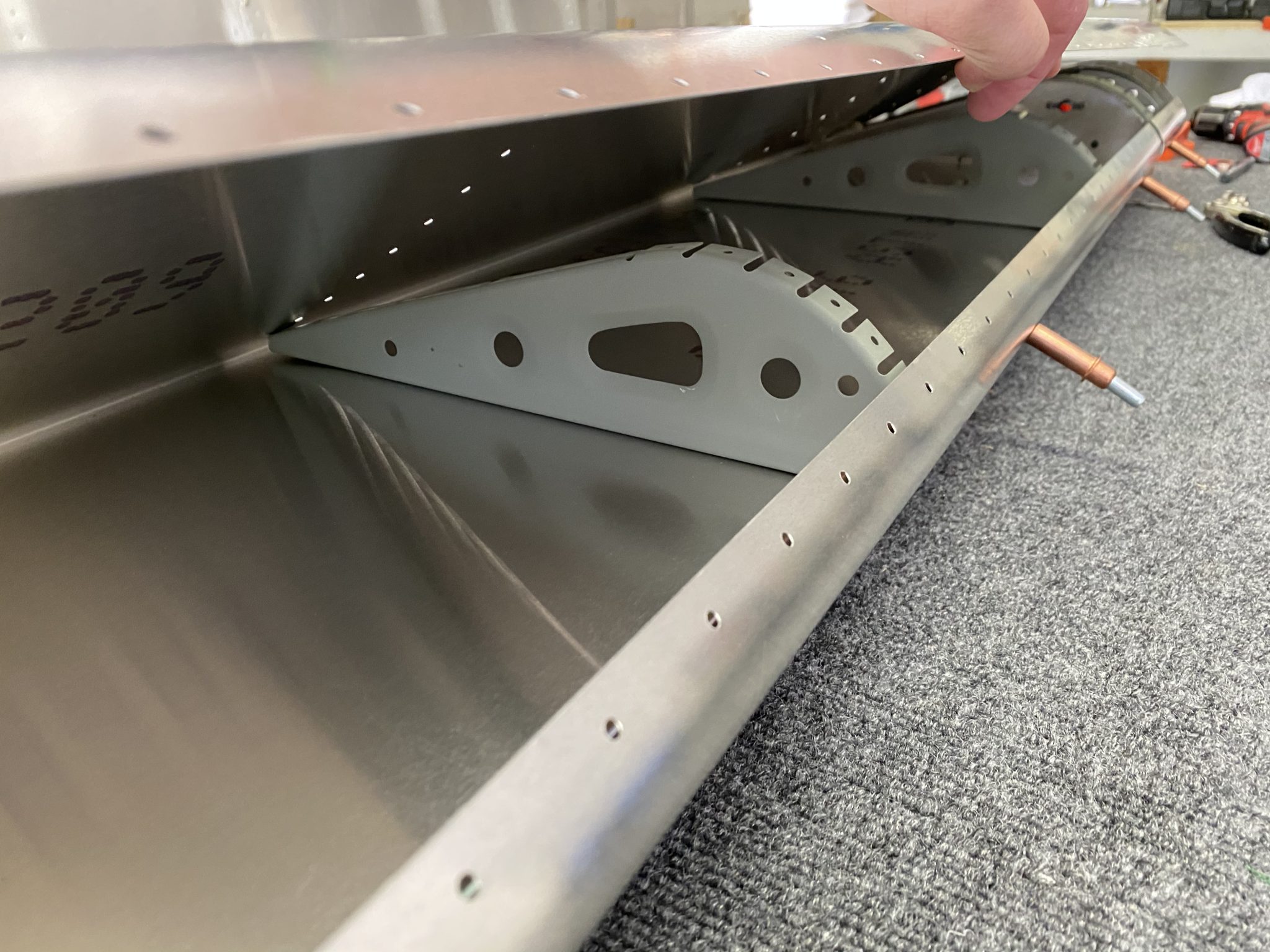
With the ribs for the ailerons prepared, time for me to complete and rivet the ribs and the skins to make a complete Aileron.
The instruction manual on the Aileron is still a bit light, so I first had to figure out the order of things. After first doing it wrong and placing the balance tube in first, I realized that this doesn’t allow to place the ribs. So back out with tube, and in with the ribs first.
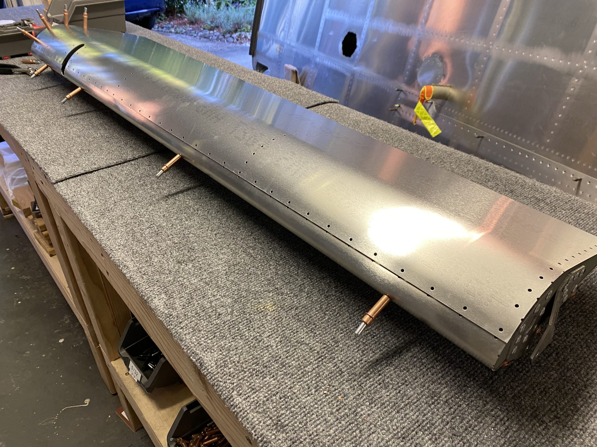
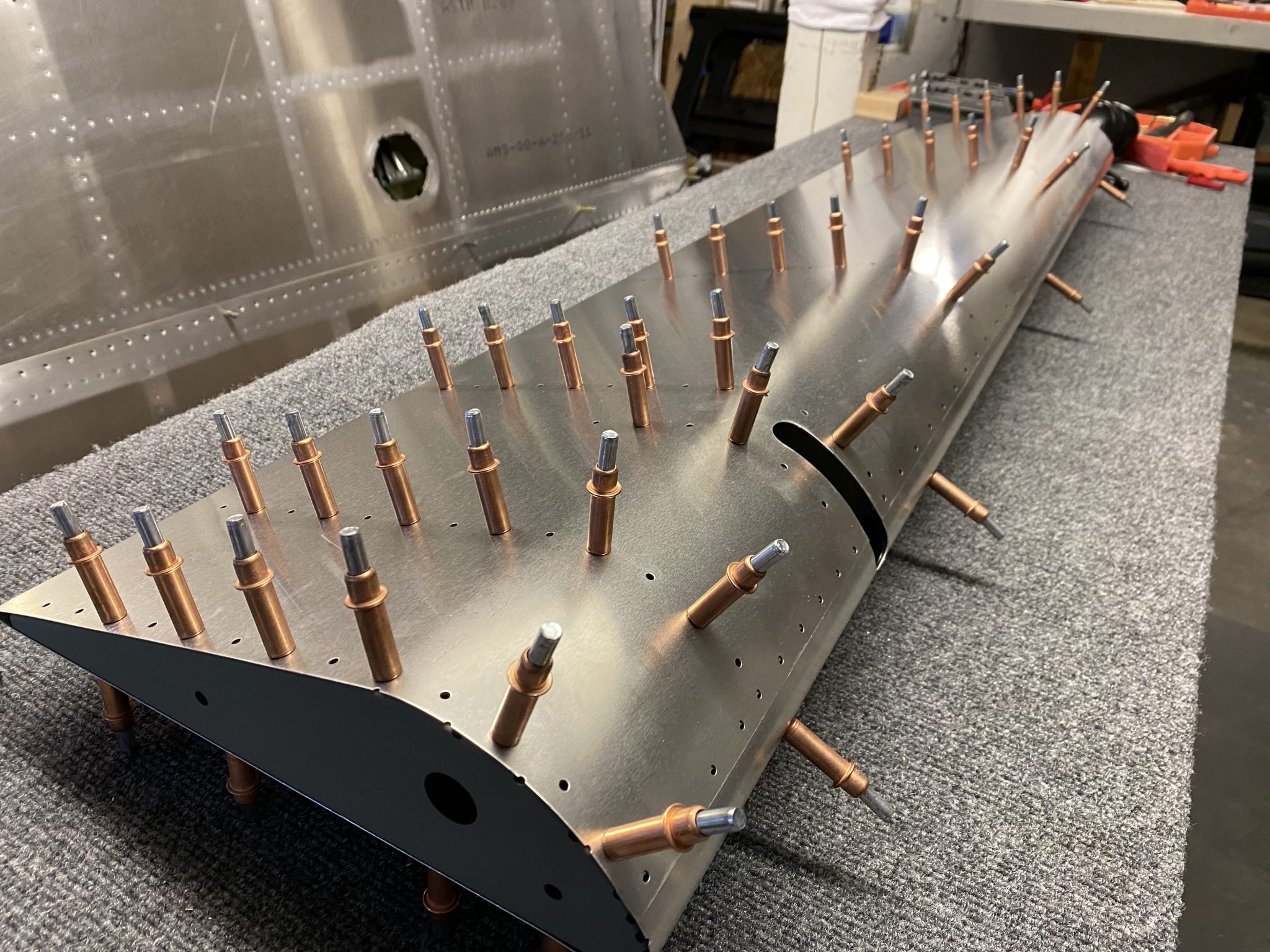
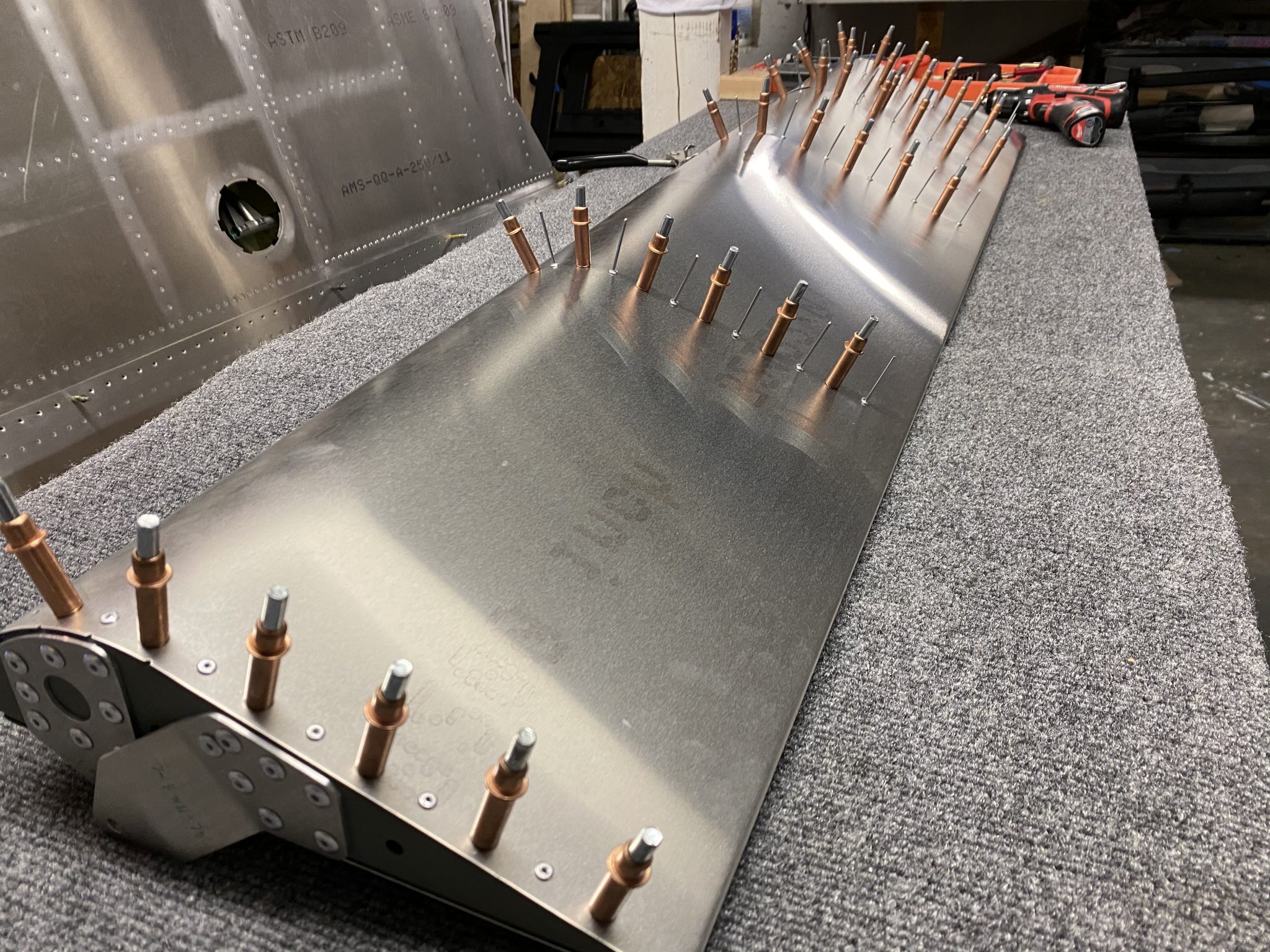
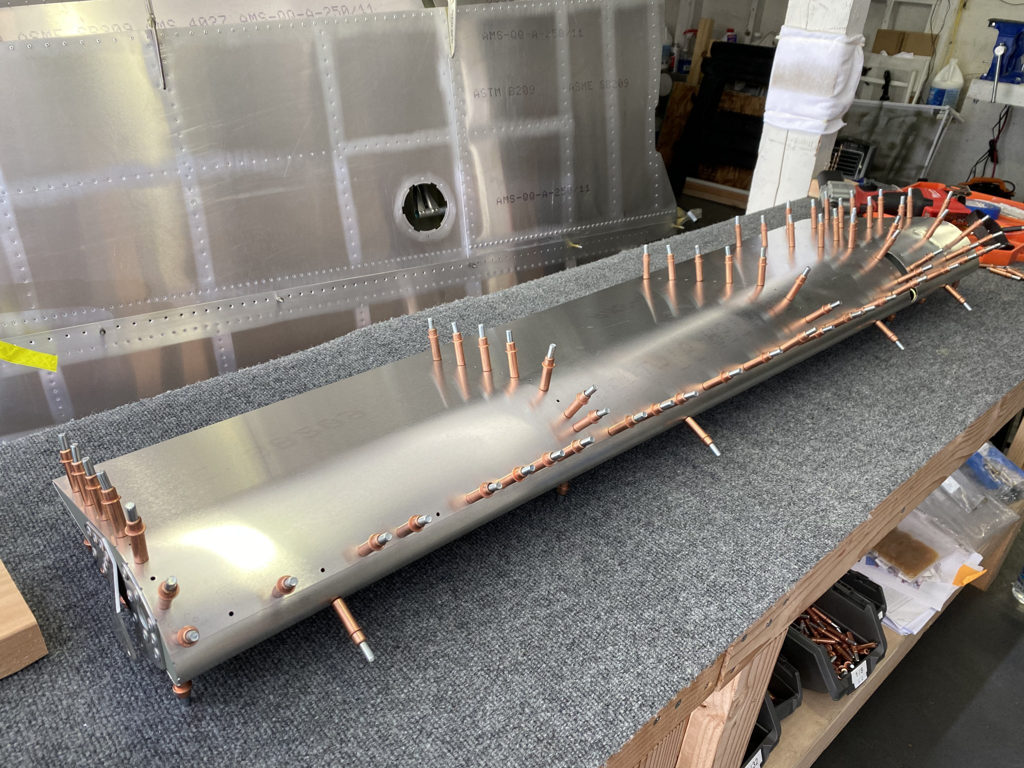
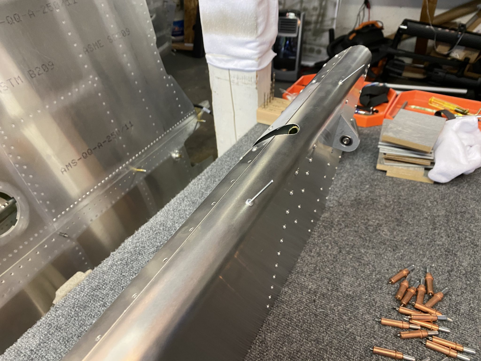
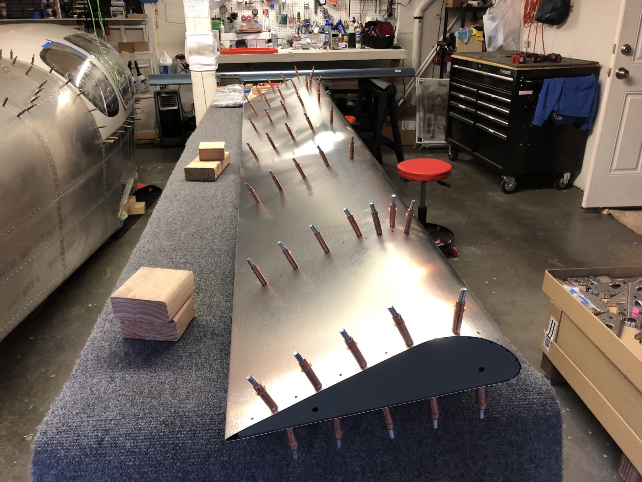
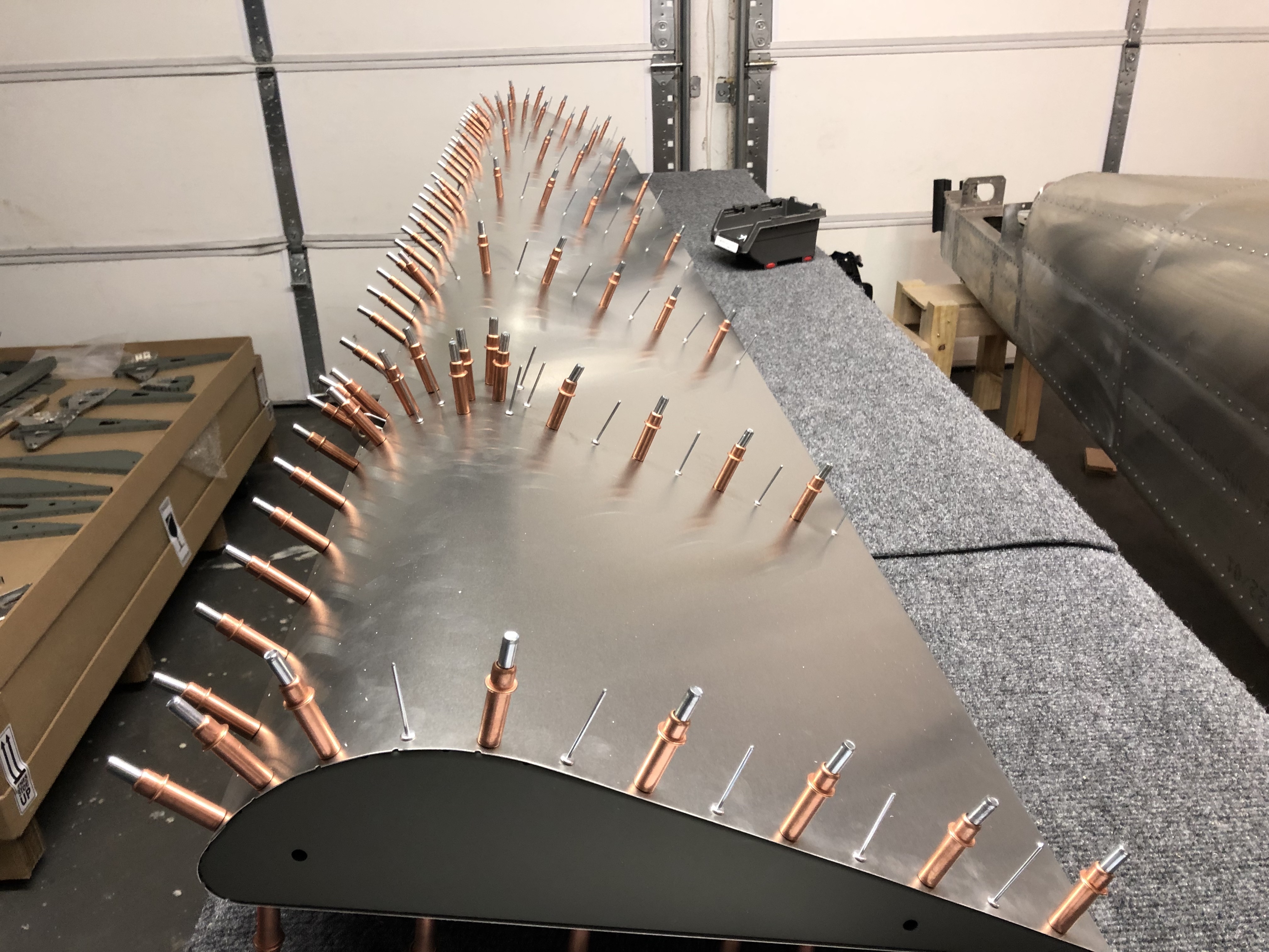
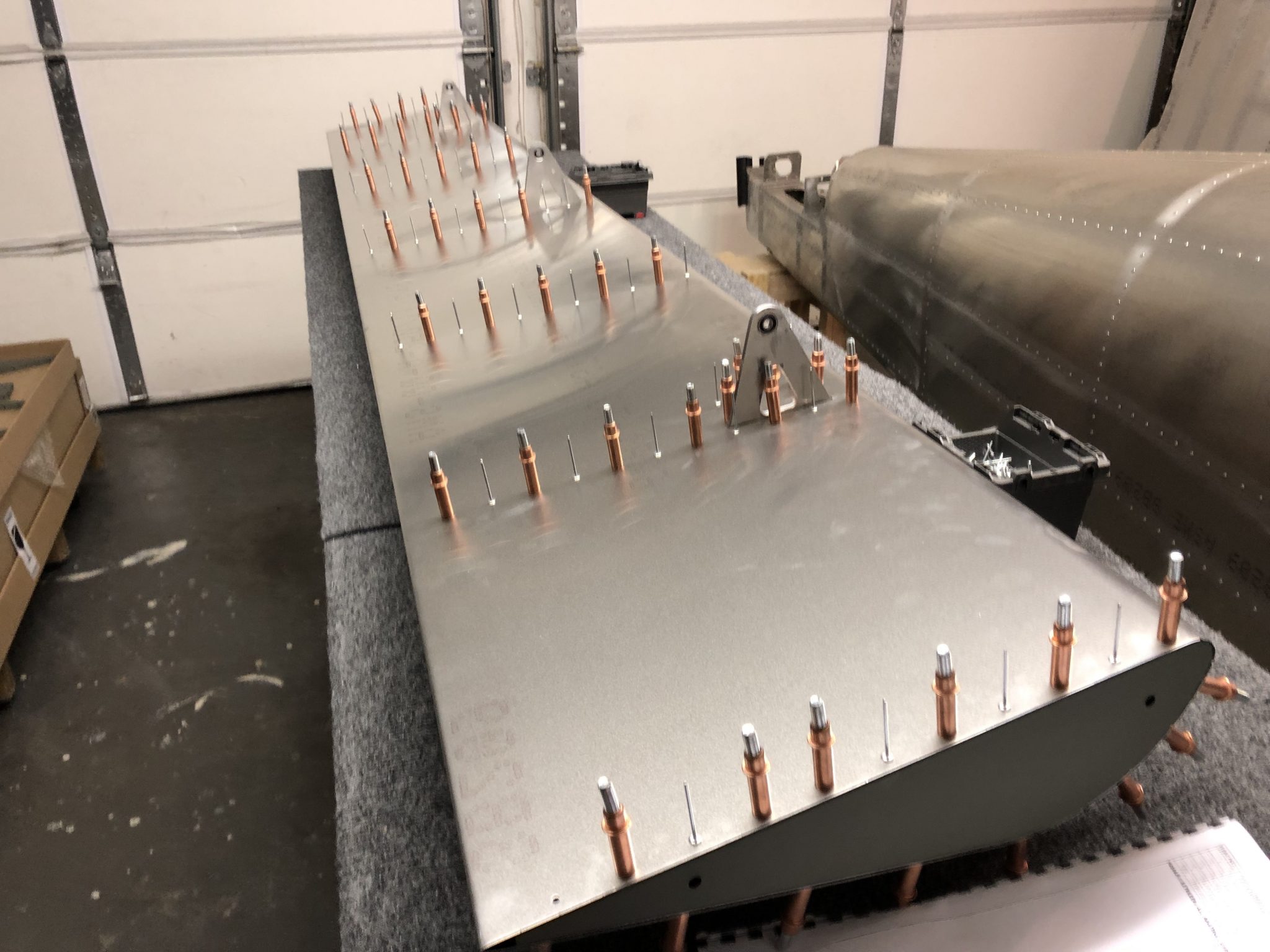
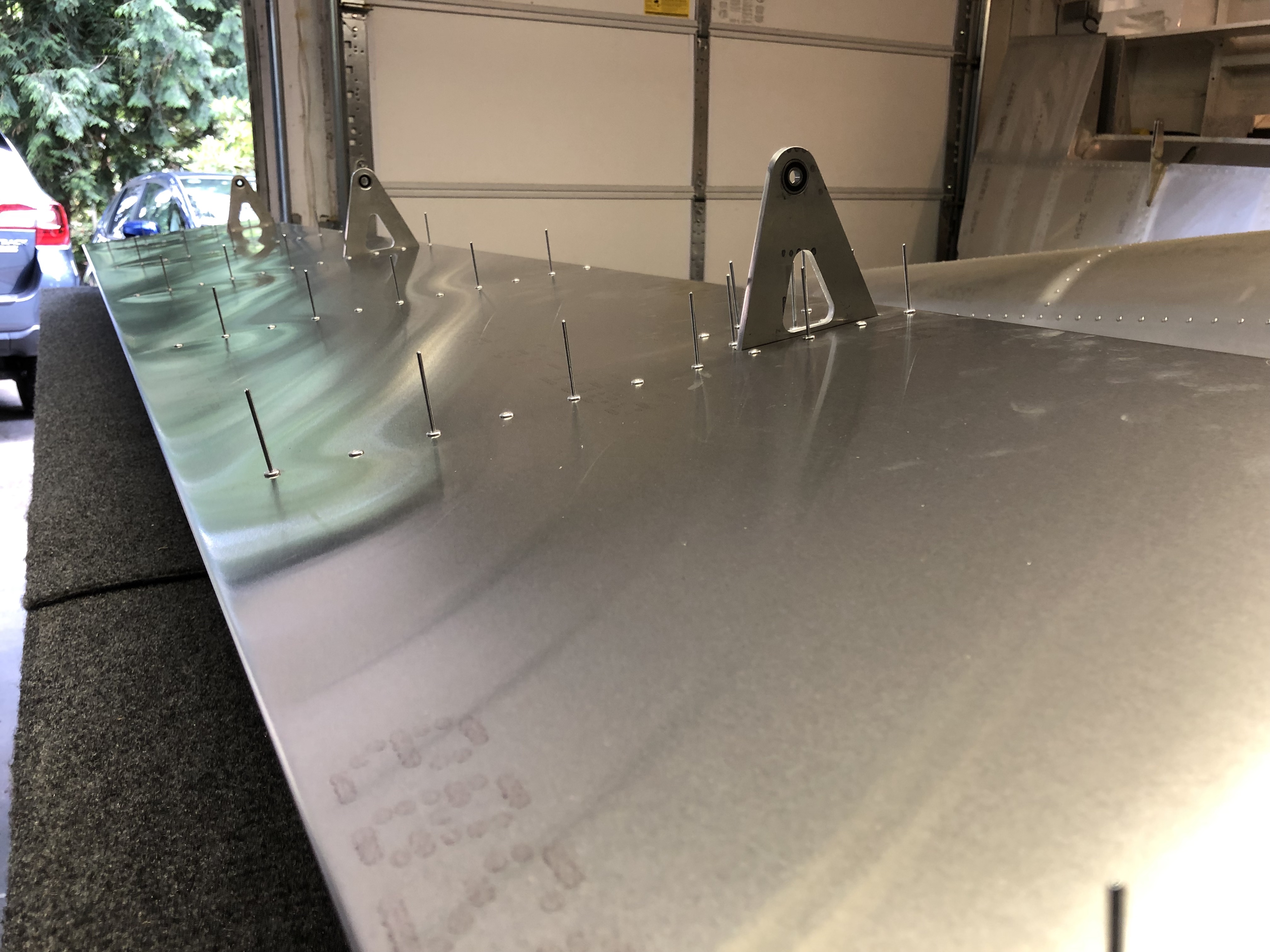
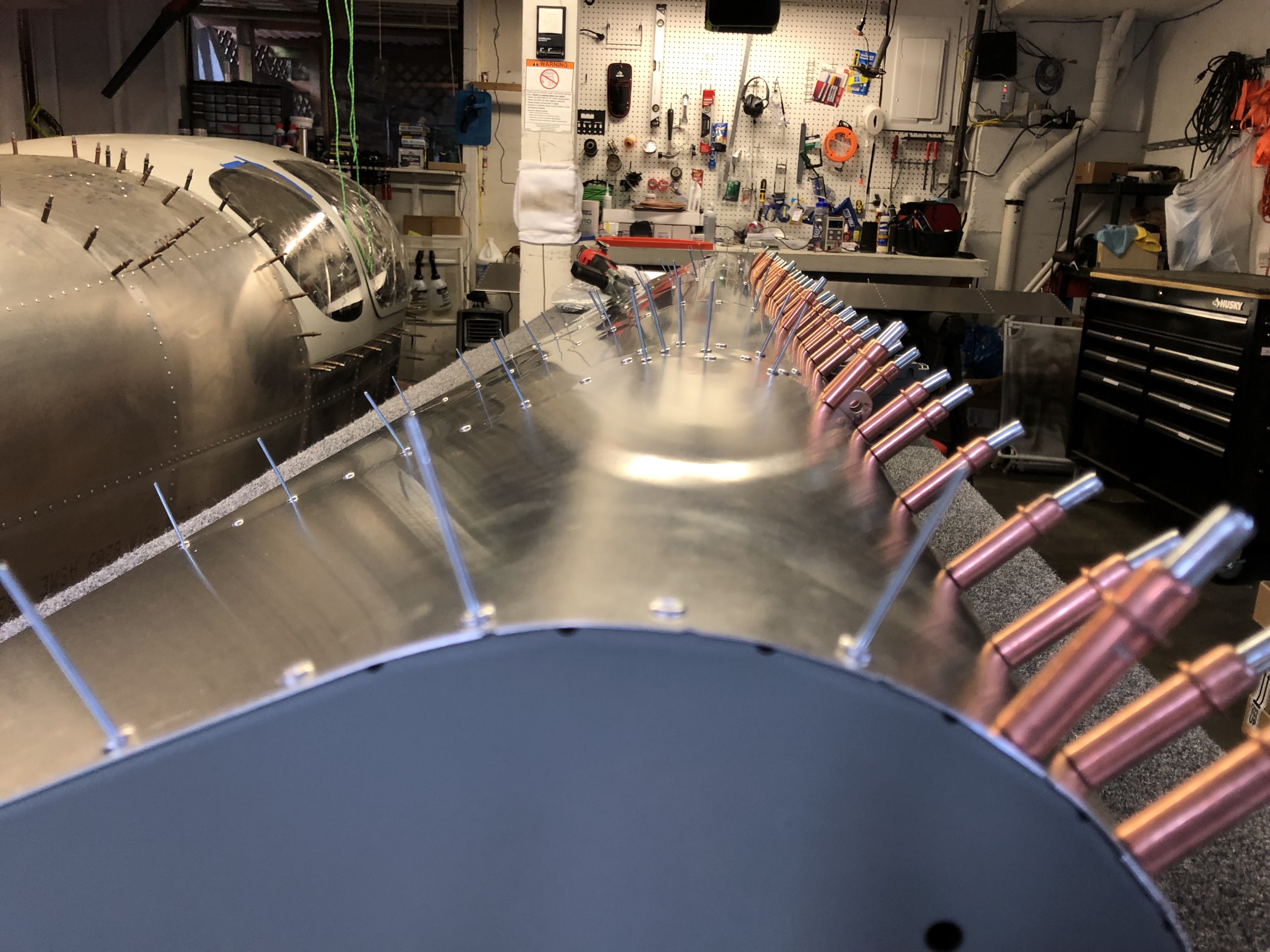
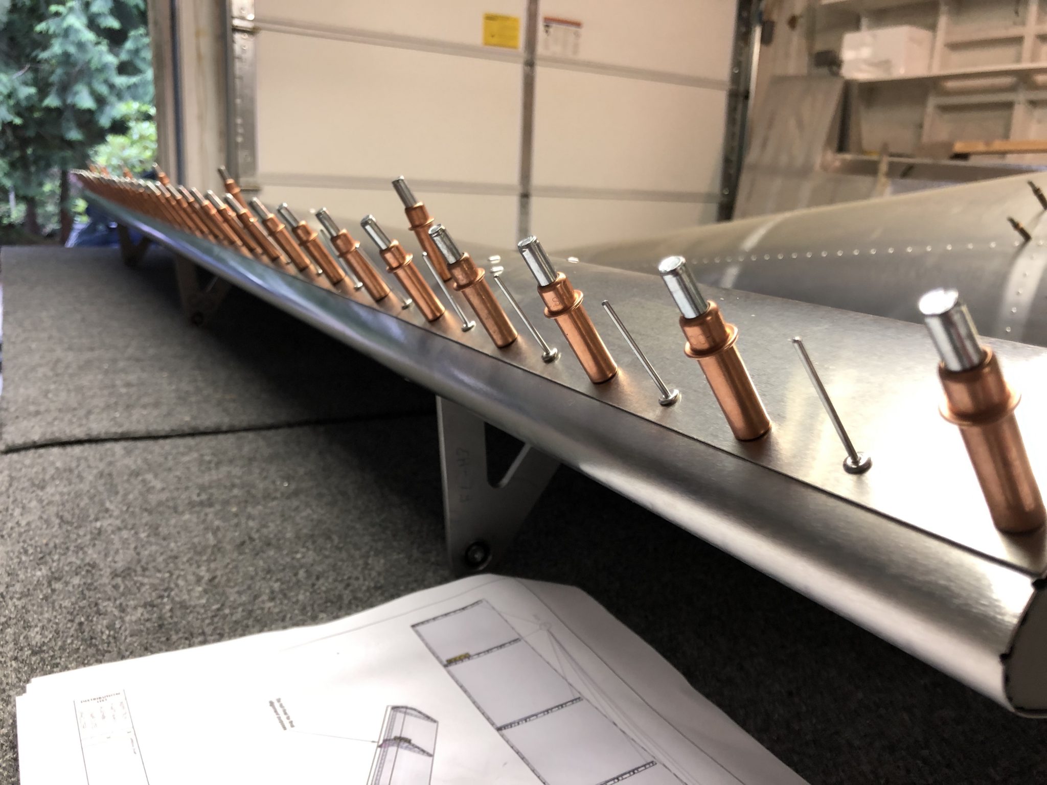
After I aligned all the ribs I inserted the balance tube and lined it up with the rivet holes. Then I clecoed both sides to start riveting the top and bottom of the skins.
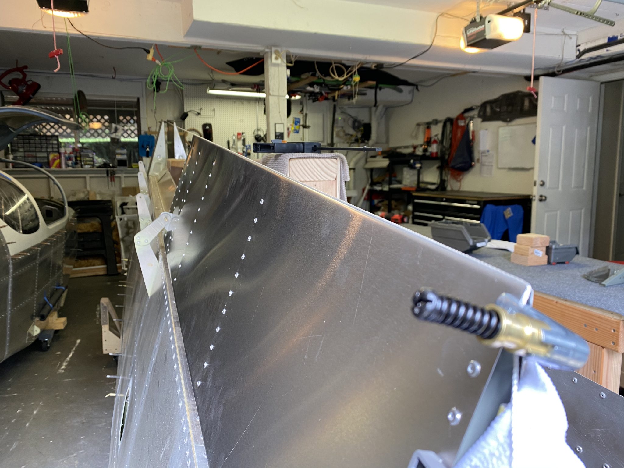
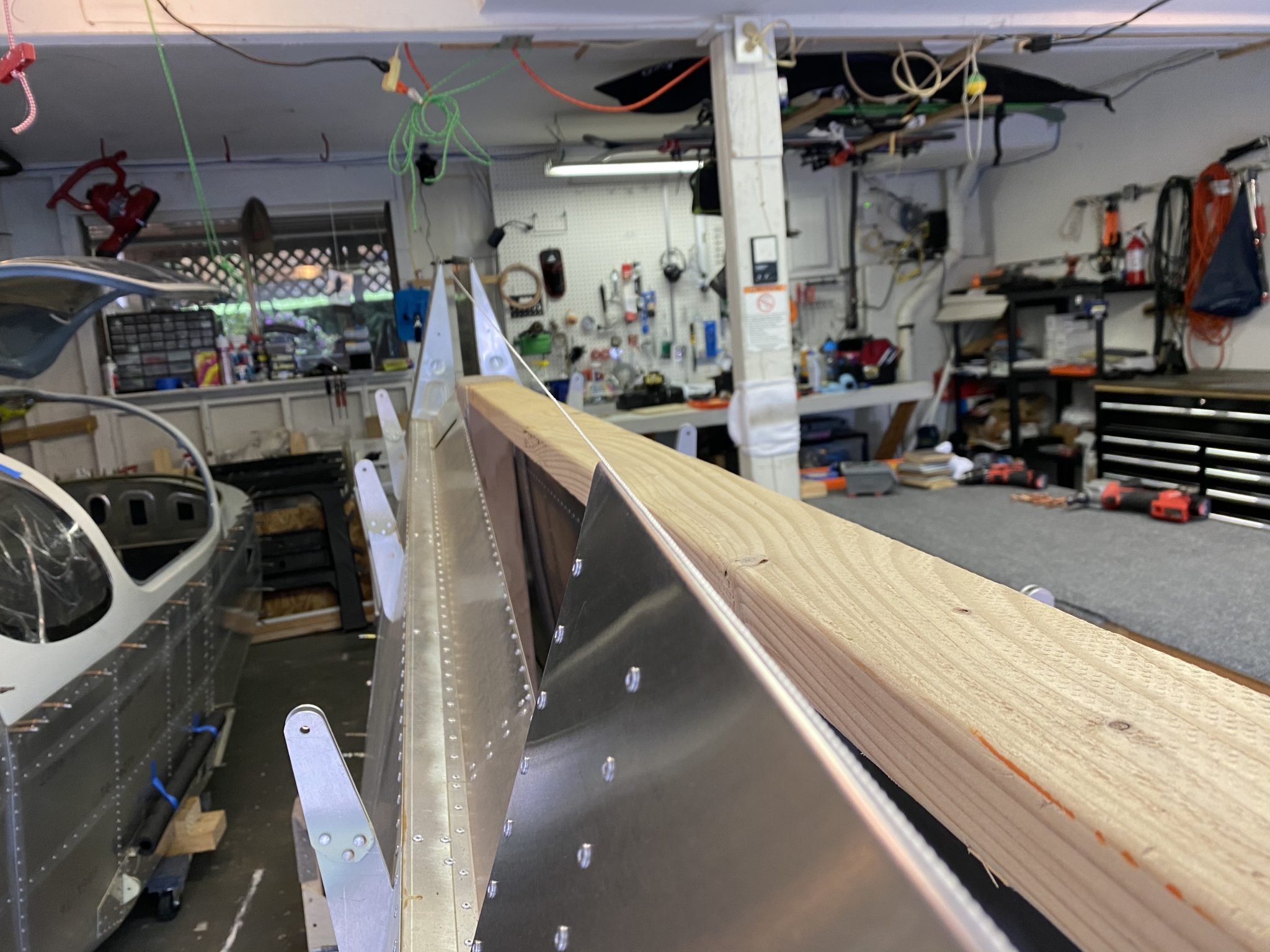
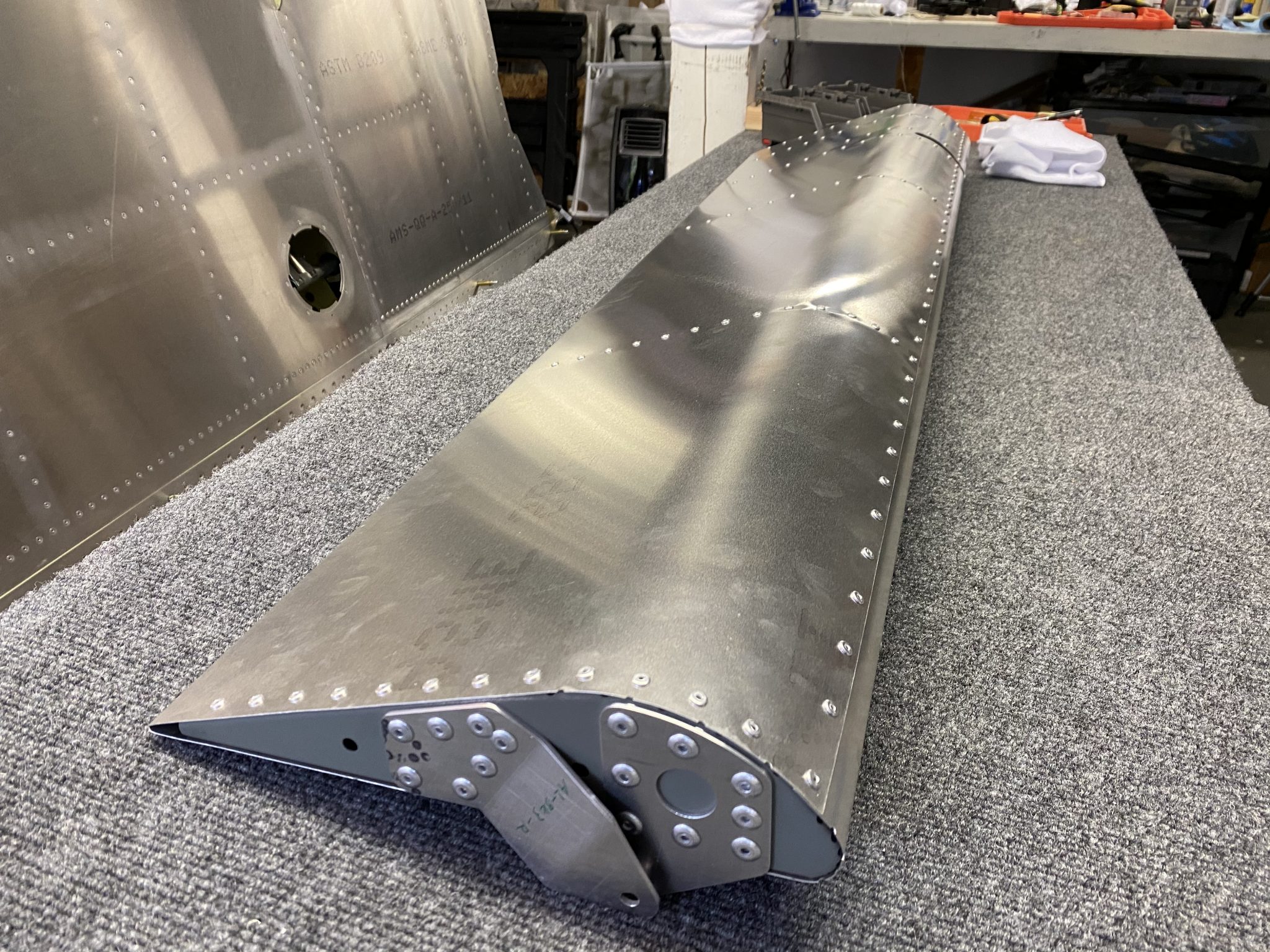
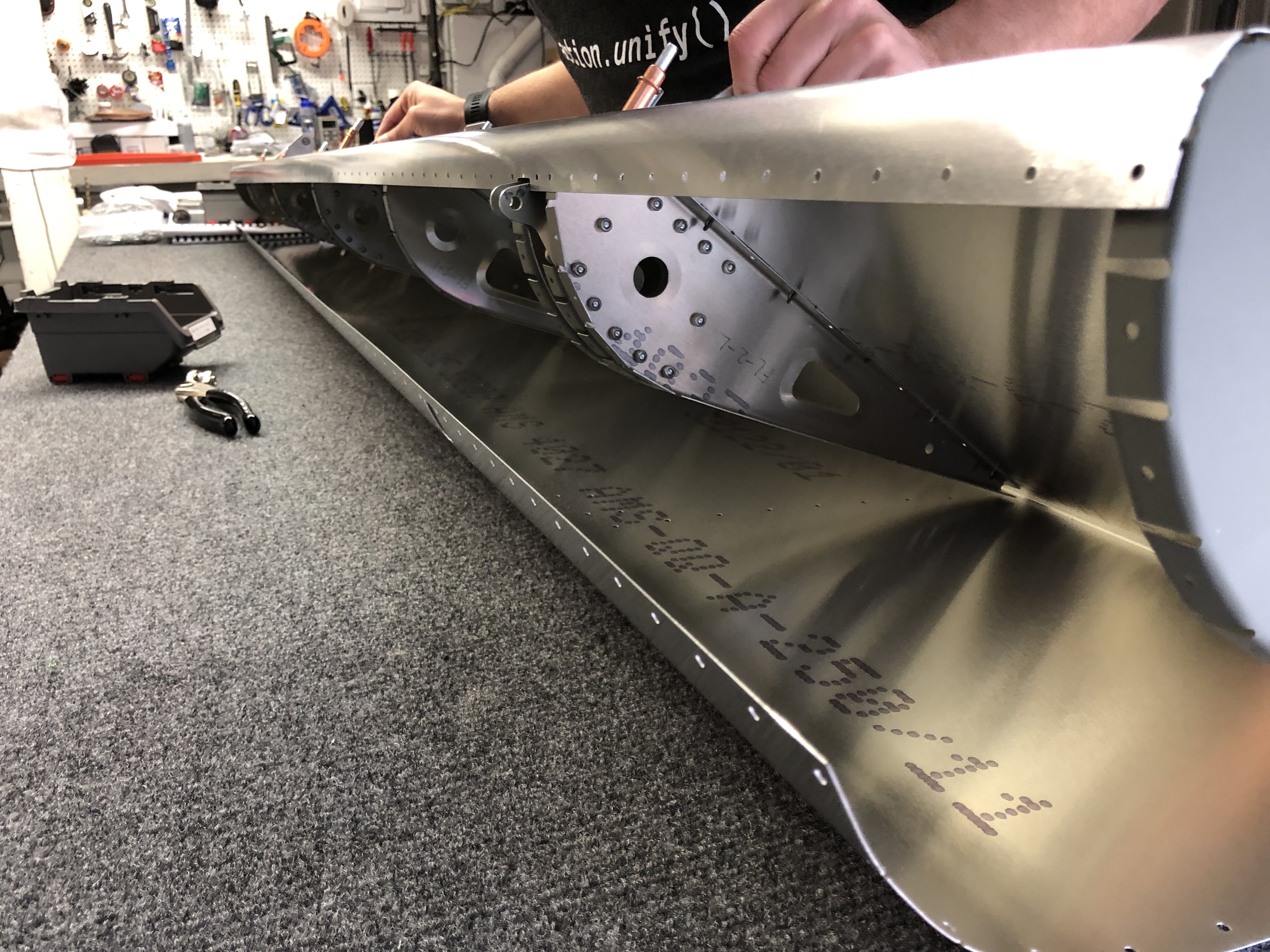
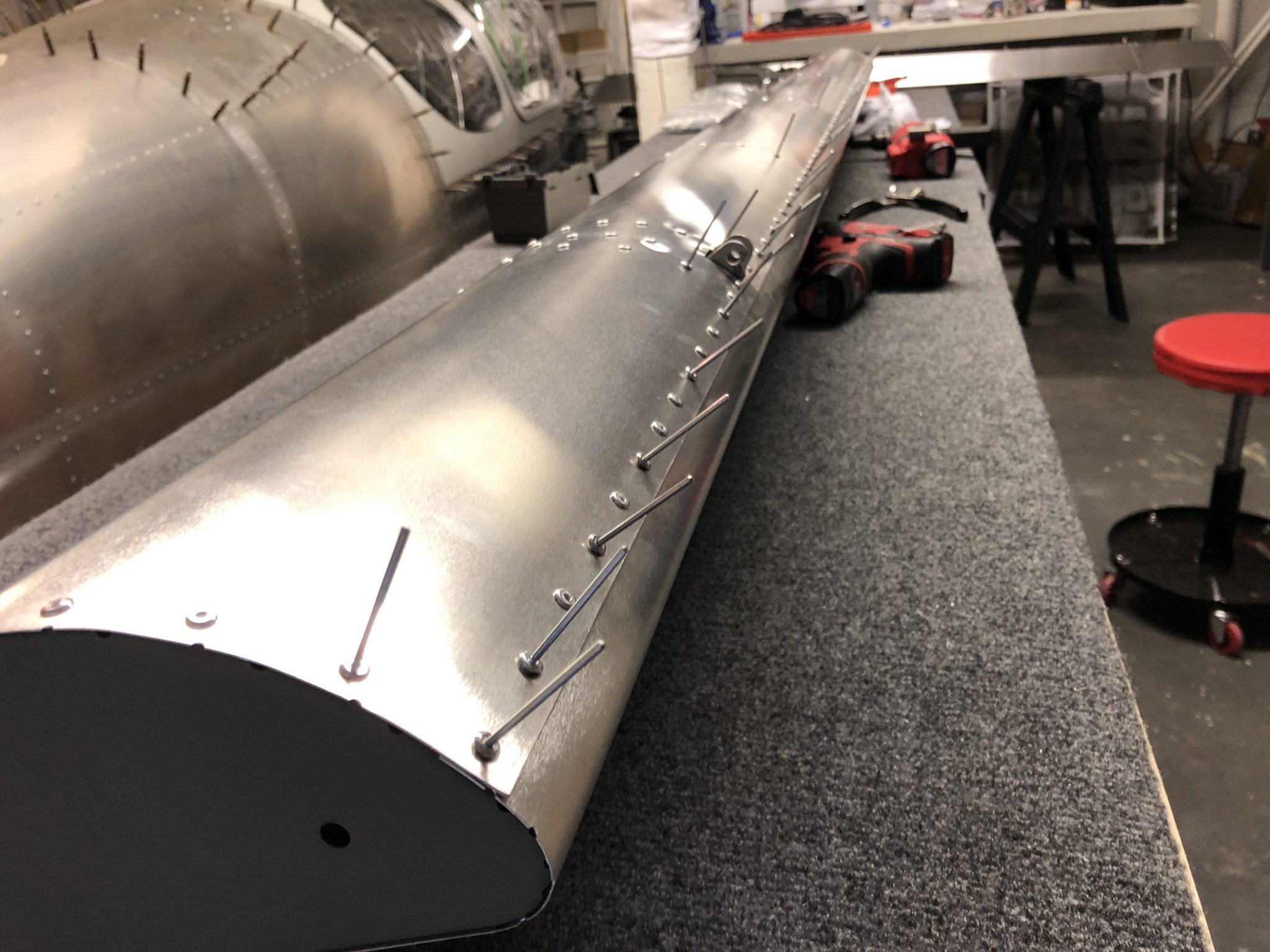
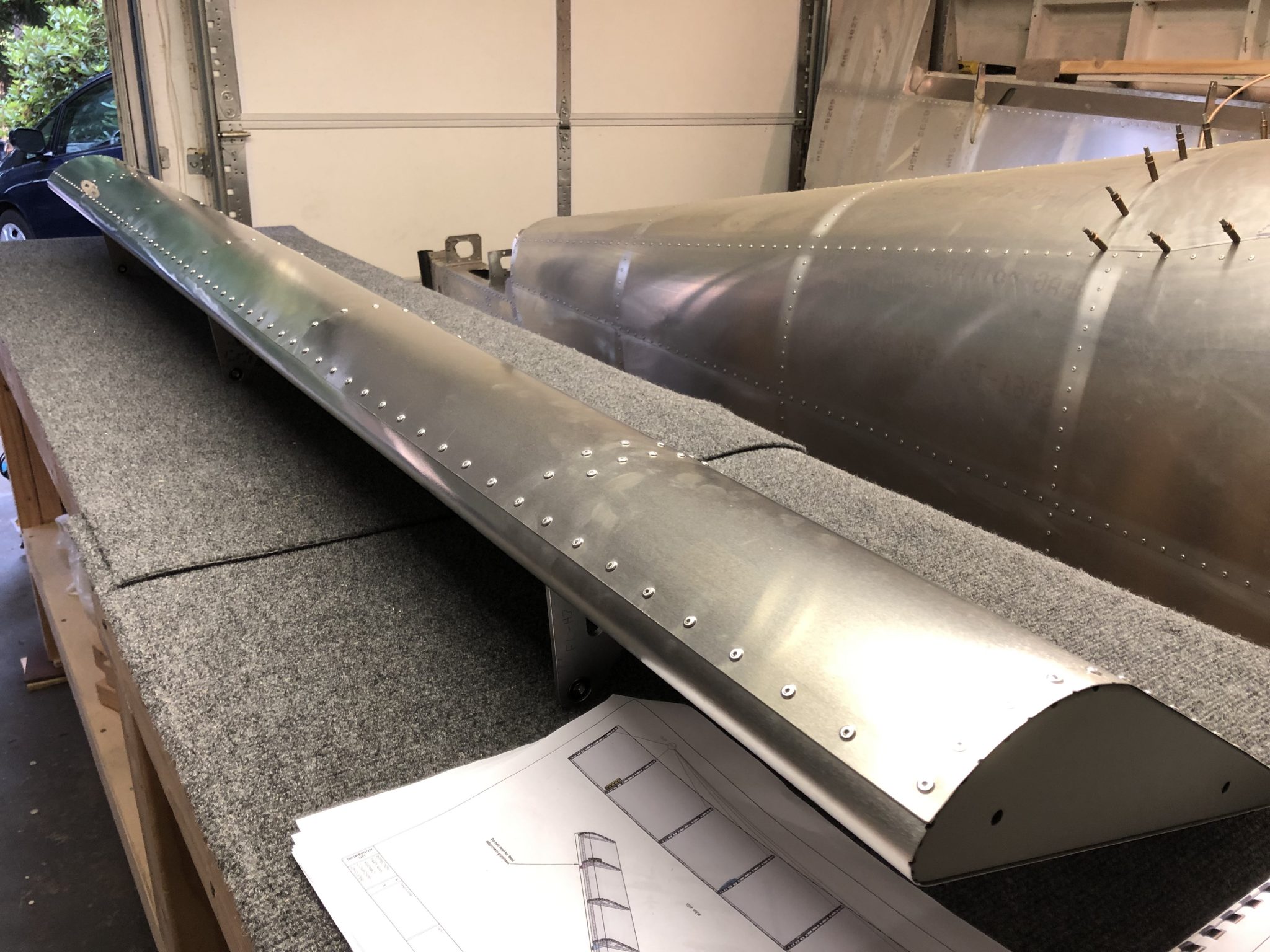
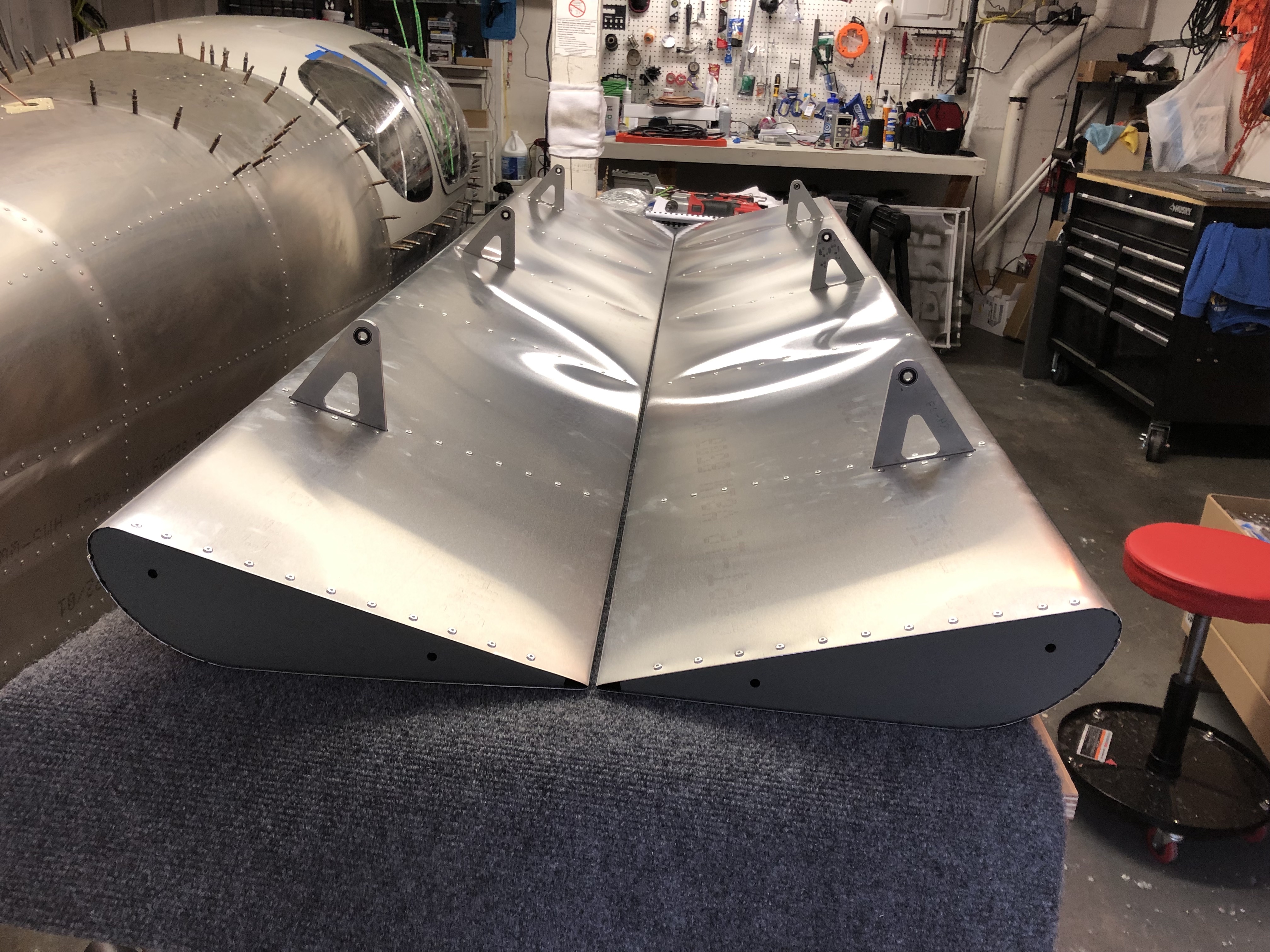
After I was done with riveting the top and bottom of the skins, I took off the clecos from the front and did a test fit on the wings to check the alignment.
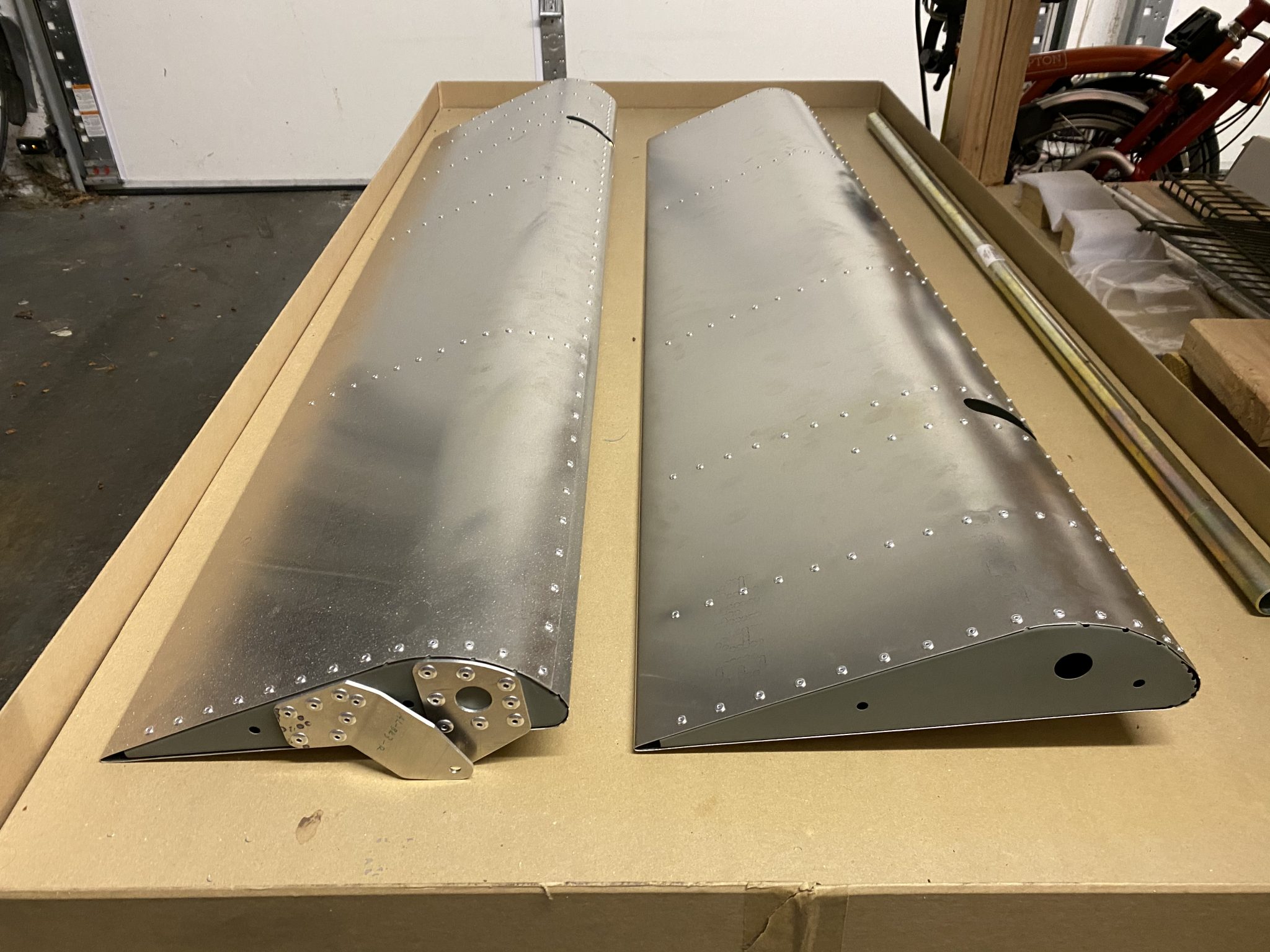
Everything looks good, so I clecoed the front line again and started riveting to finish the Aileron.
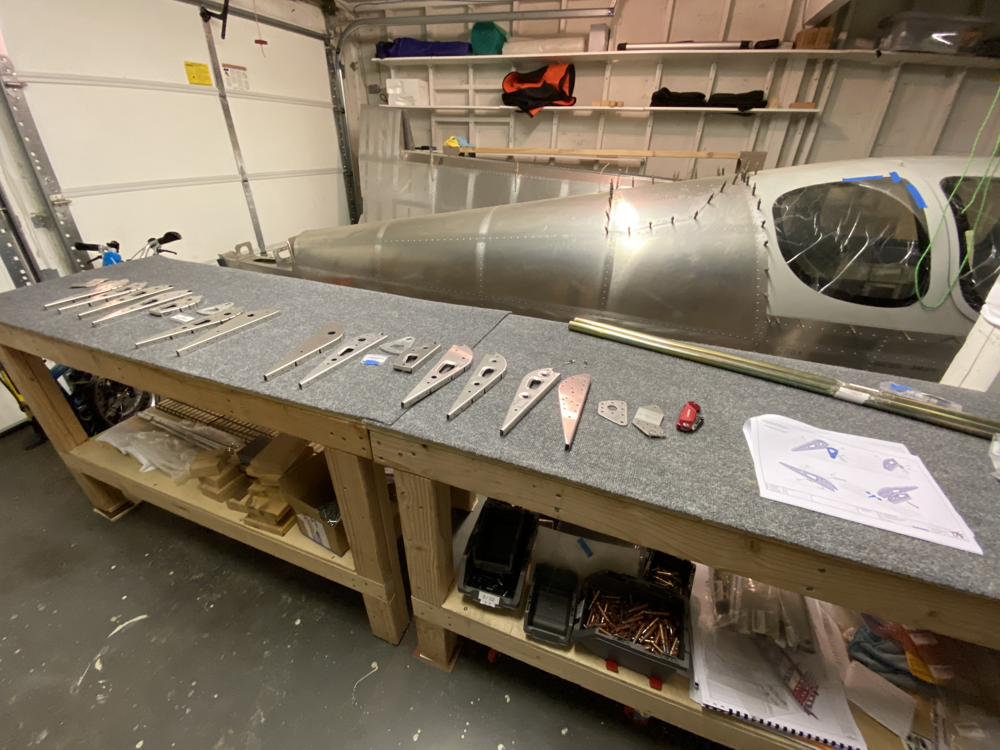
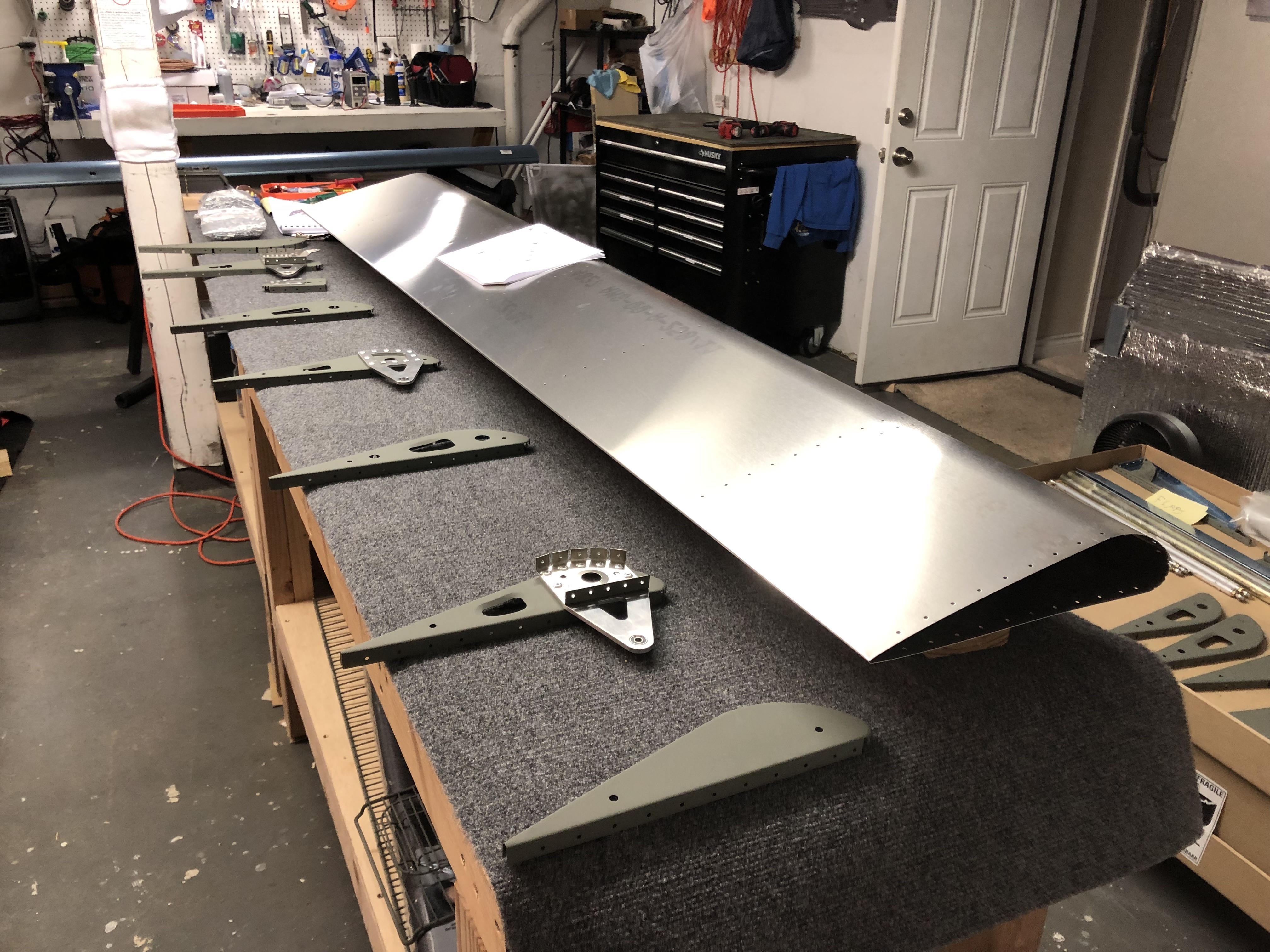
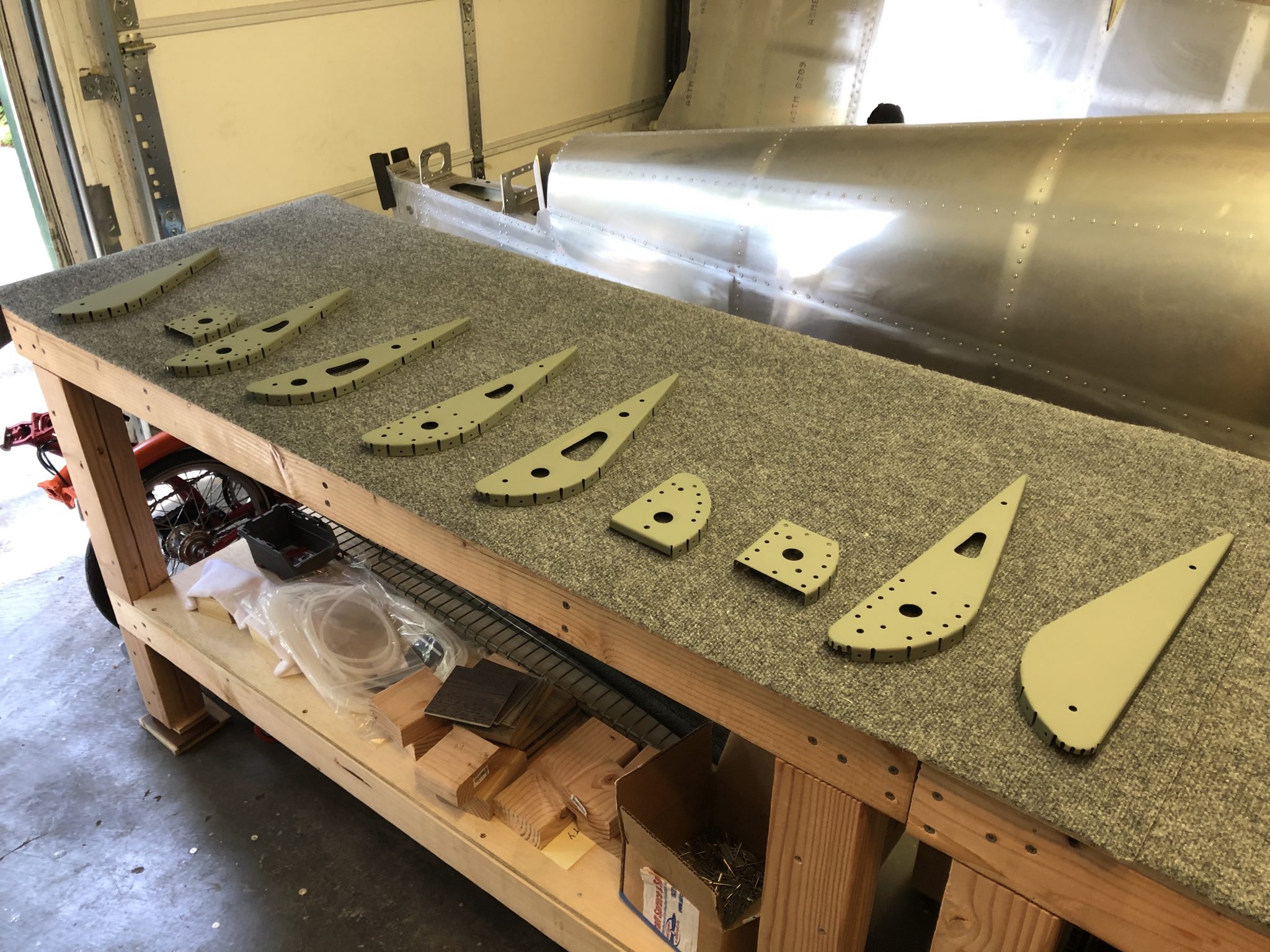
Time to finish off the external control surfaces with the Aileron. I already primed them a while back, so time to assemble the ribs.
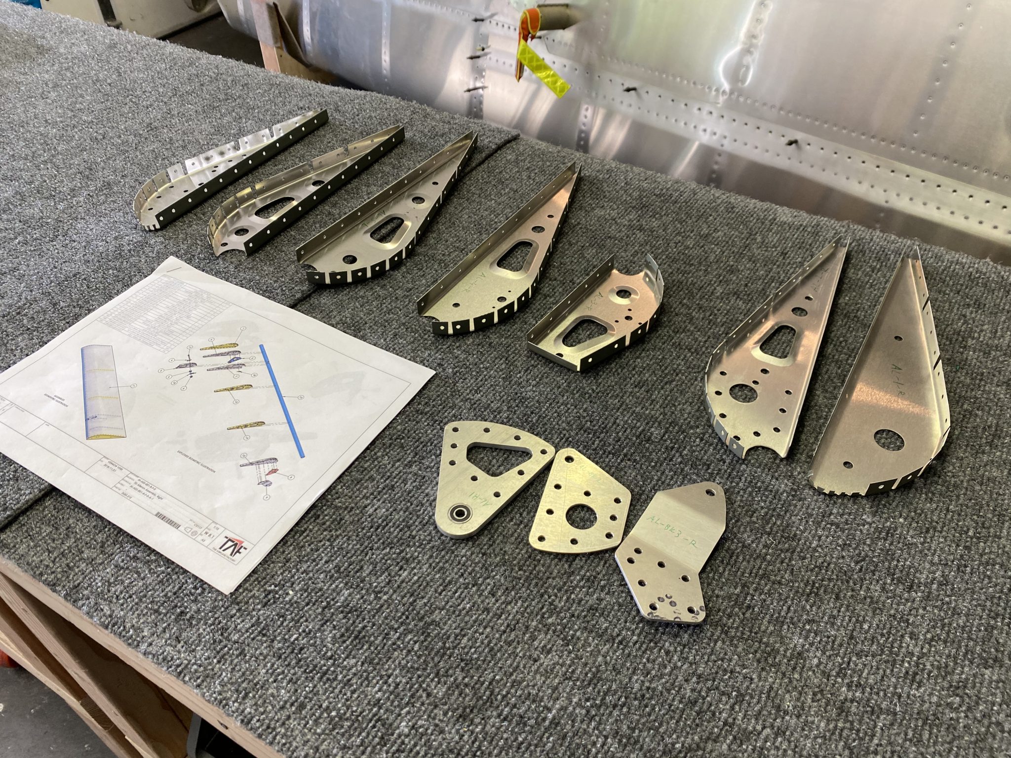
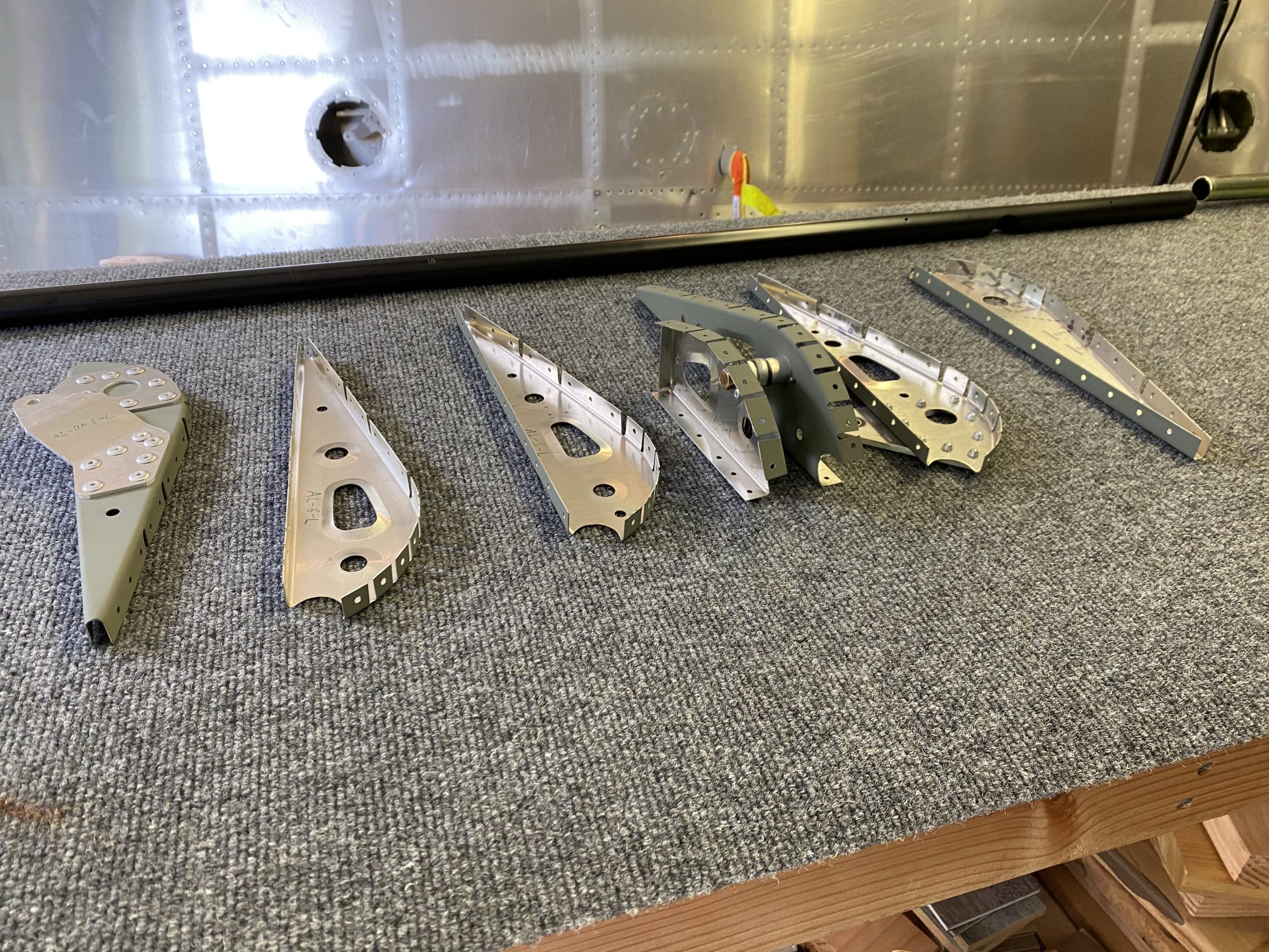
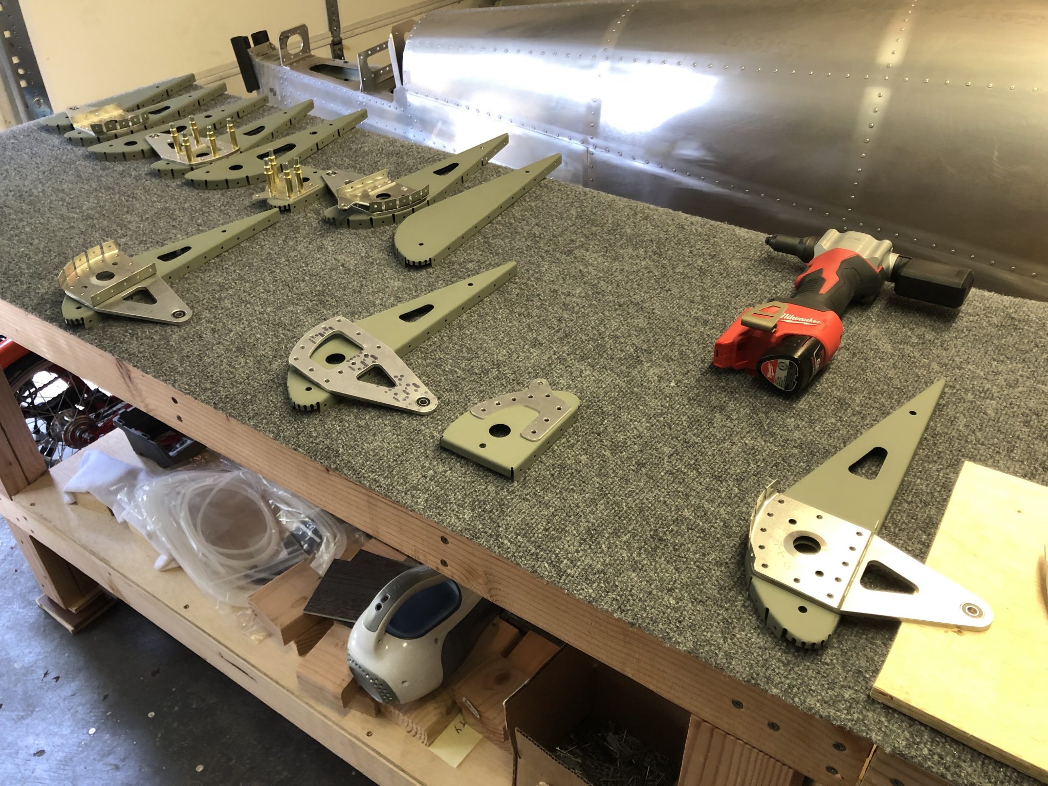
First order of business was sorting the ribs between left and right aileron. Then I checked off all the hardware needed. I already knew from my earlier investigating that the AN bolts for this is in the finishing kit, and the eyebolts are attached to the control rods.
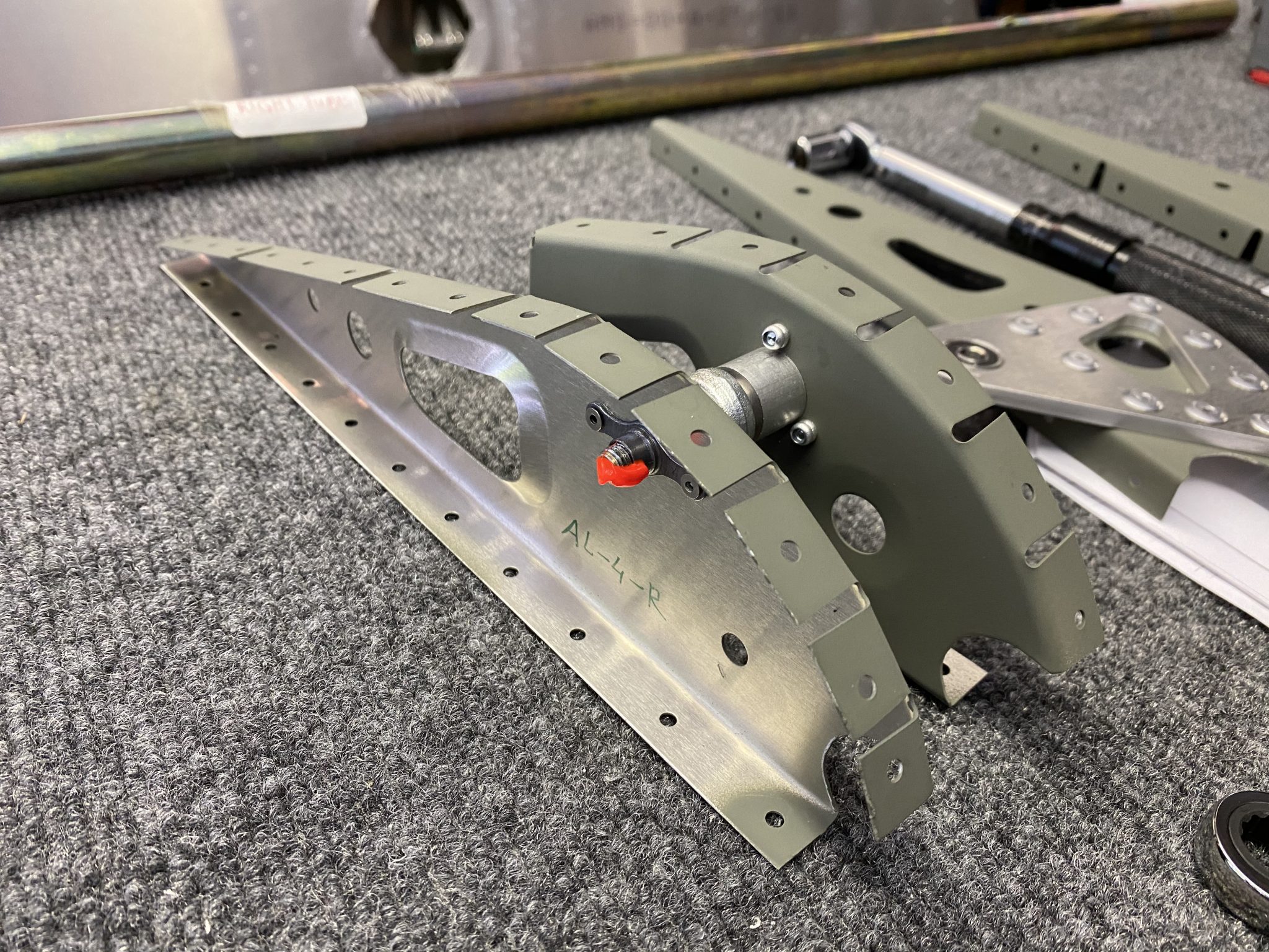
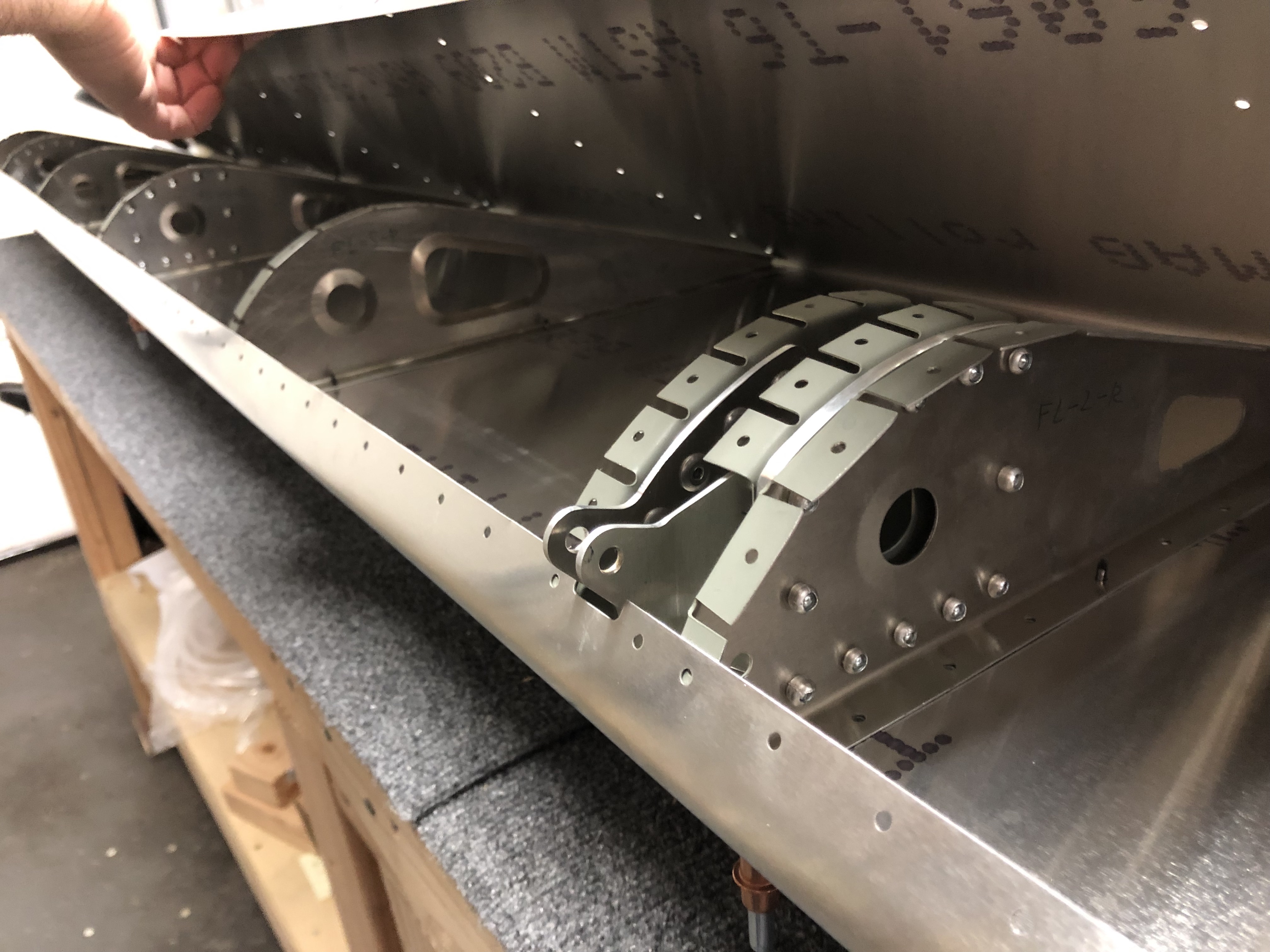
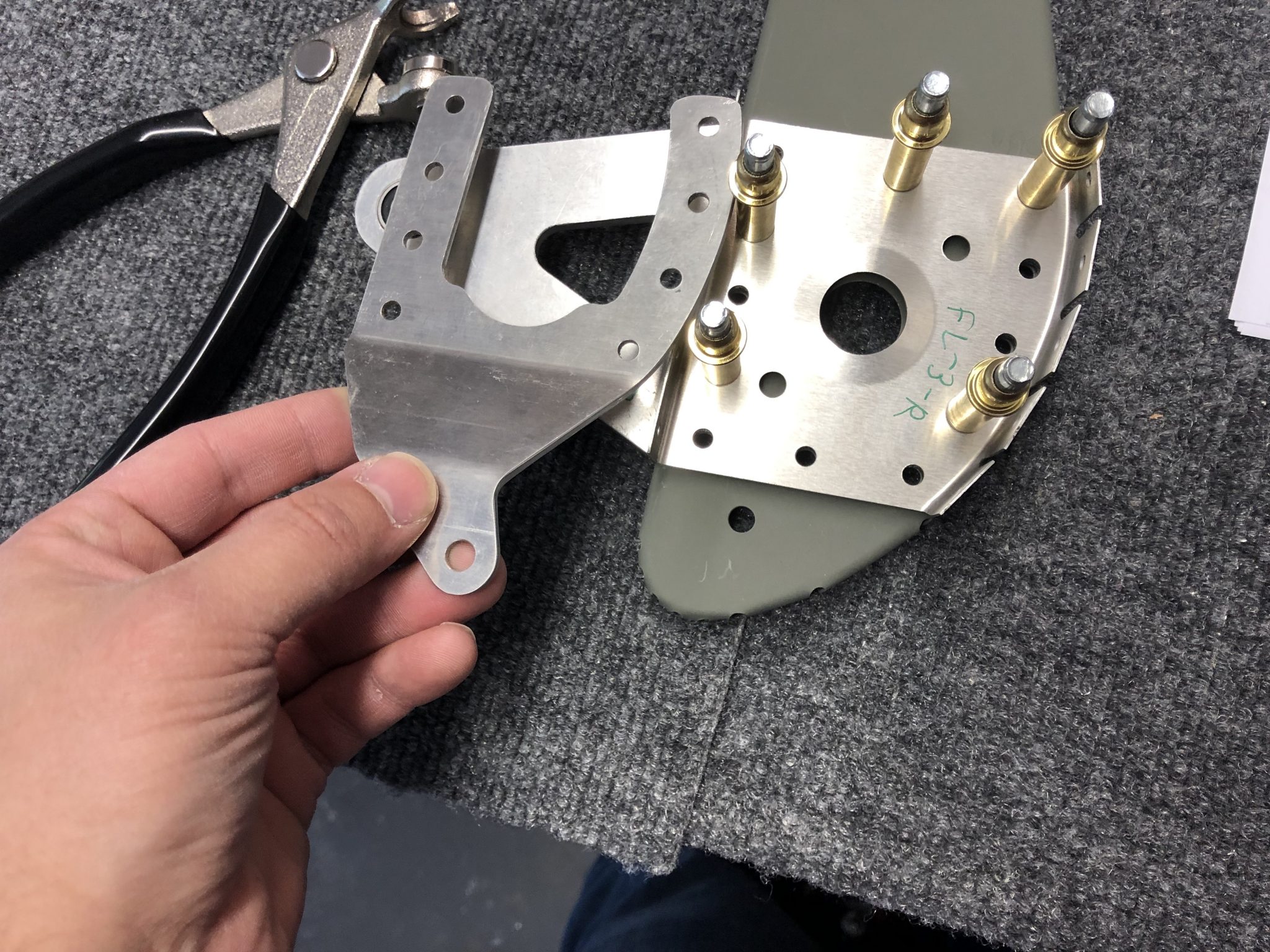
After laying them out, I started riveting the control brackets using the 4.8 mm rivets.
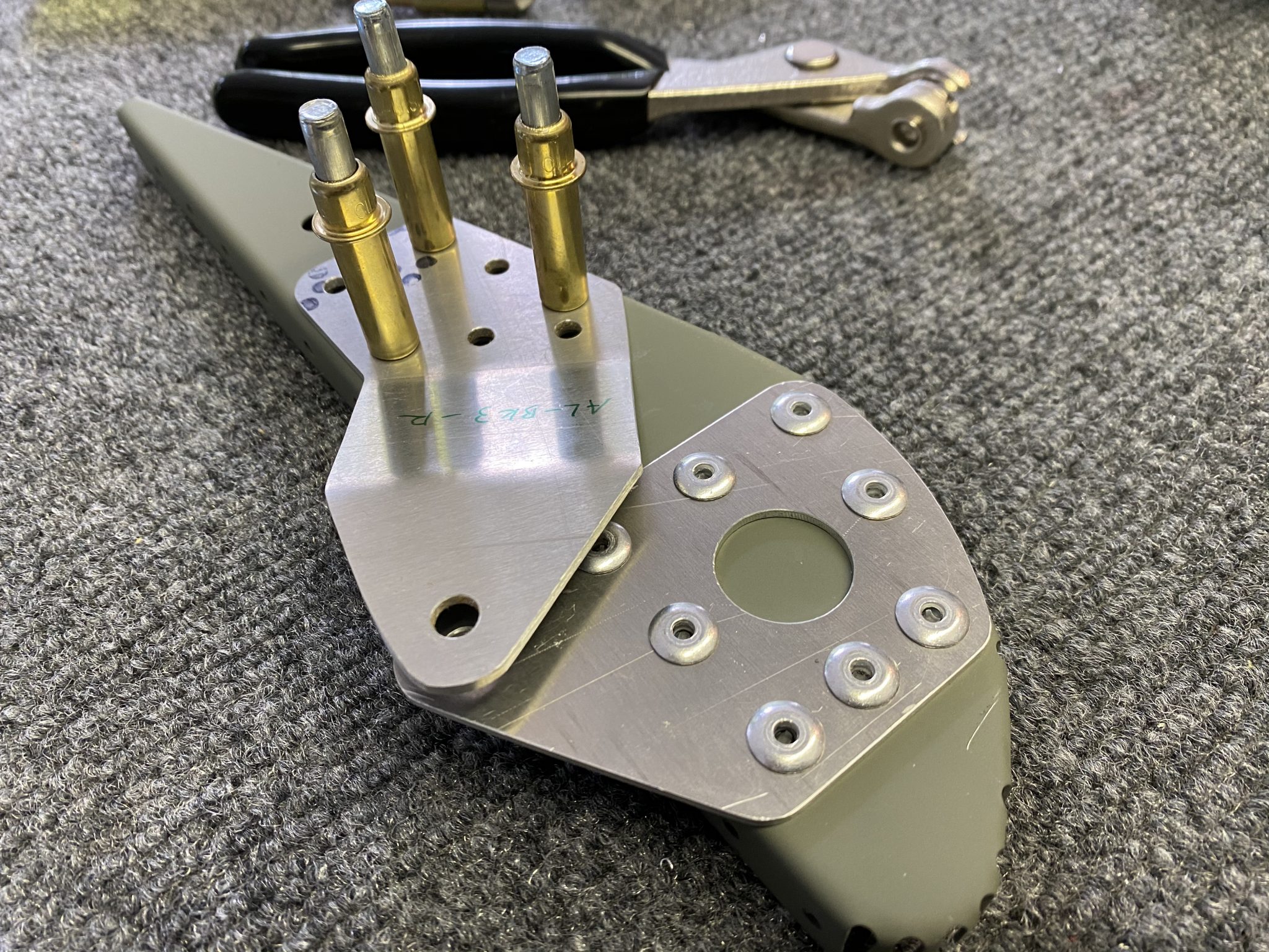
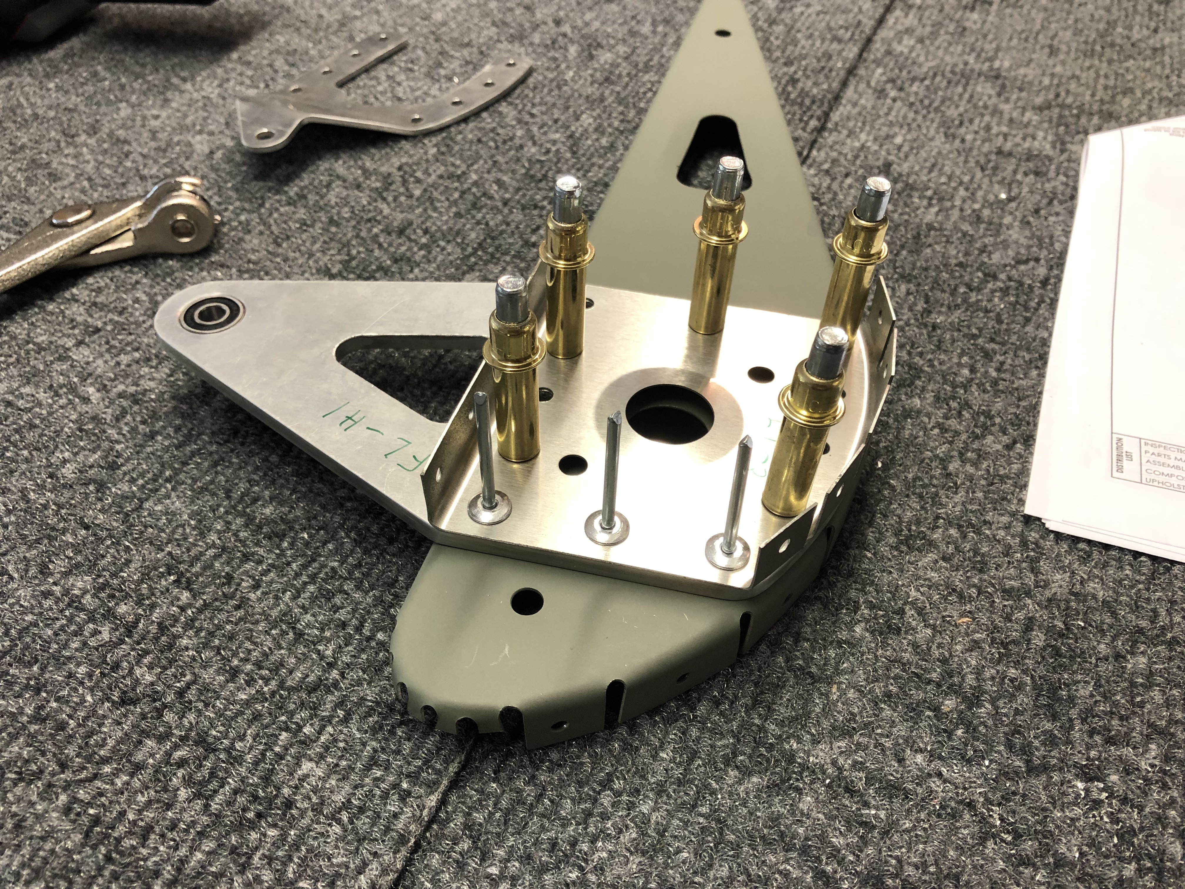
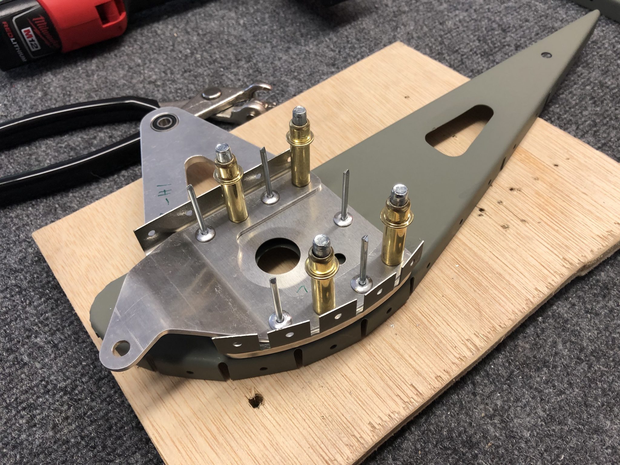
Then for rib 7 I laid out both brackets. The instructions are missing details about this rib, but it was easy to figure out that it uses the remaining 4.8 mm rivets (24 total per the part list, 9 are used for bracket 1, and counting out the holes of bracket 2 and 3, it comes to 24). I also noticed that one bracket slightly overlaps the other, which means that first I had to fully rivet the bracket 3:
With this completed, I then riveted the hinge bracket 2.
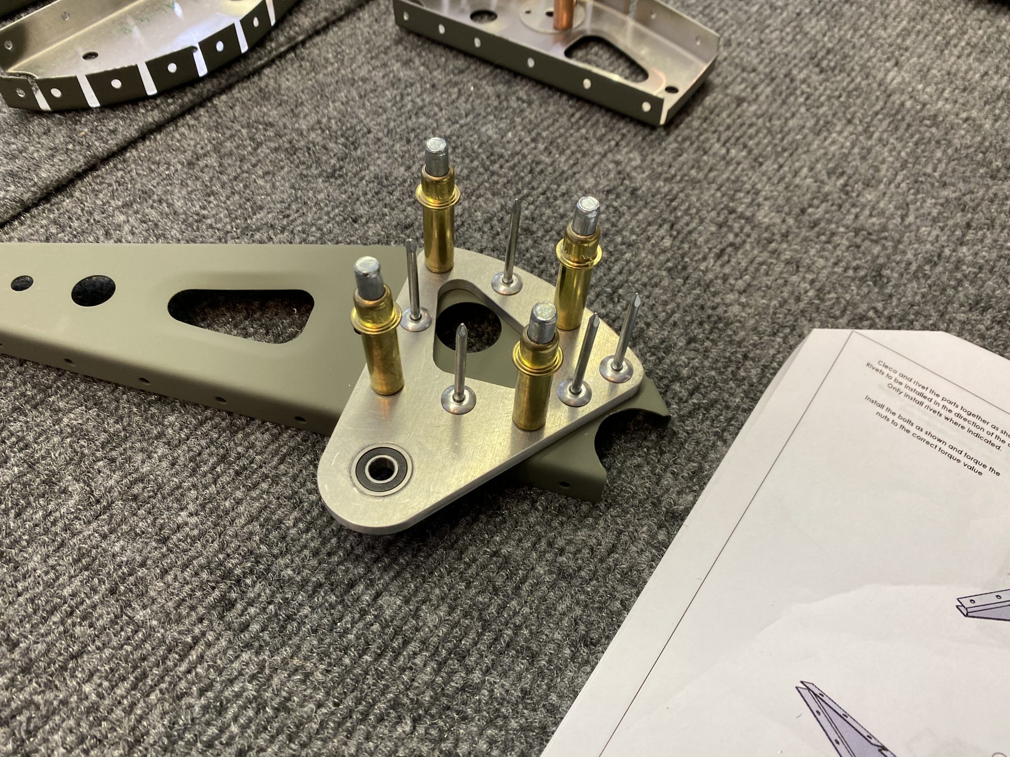
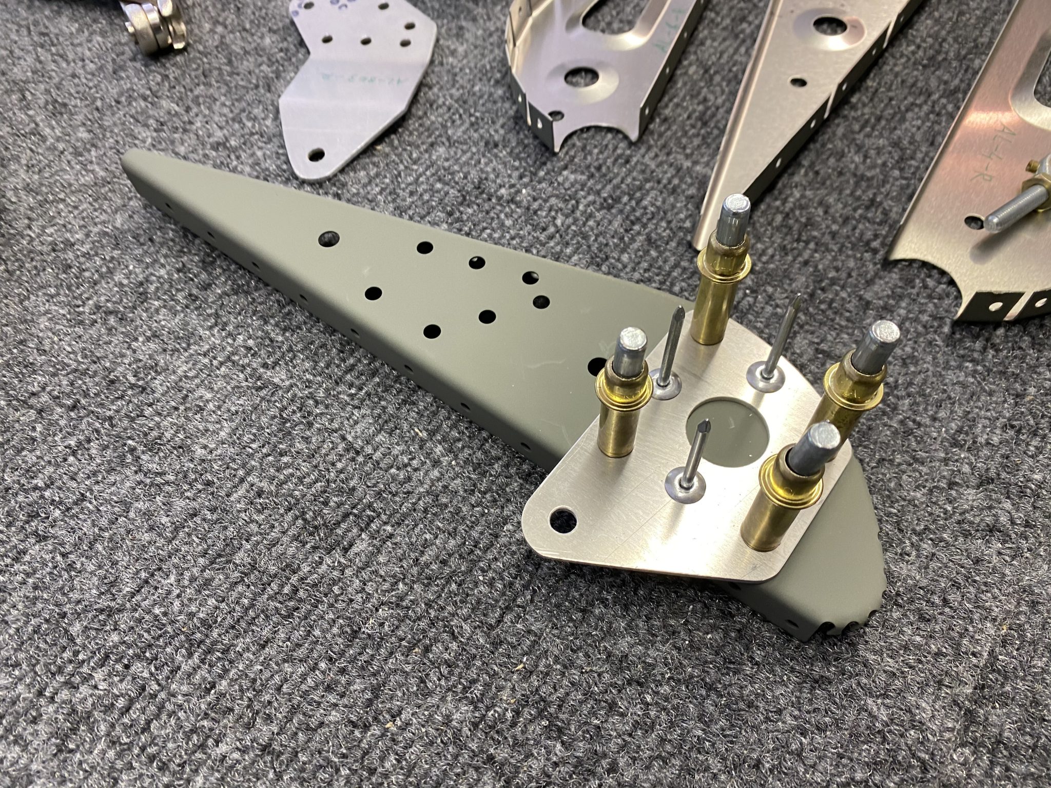
The final rib that needs preparation is the assembly of the Eyebolt attachment that controls the movement of the aileron. I put it all together and then torqued it and placed some torque marker on it.
Then I repeated everything for the left Aileron ribs. Next step will be to lay all the ribs into the skins and rivet it closed.
After a couple of weeks of taking some time off active building while life happens and figuring out and planning out some things, I’m back to actively riveting on the airplane.
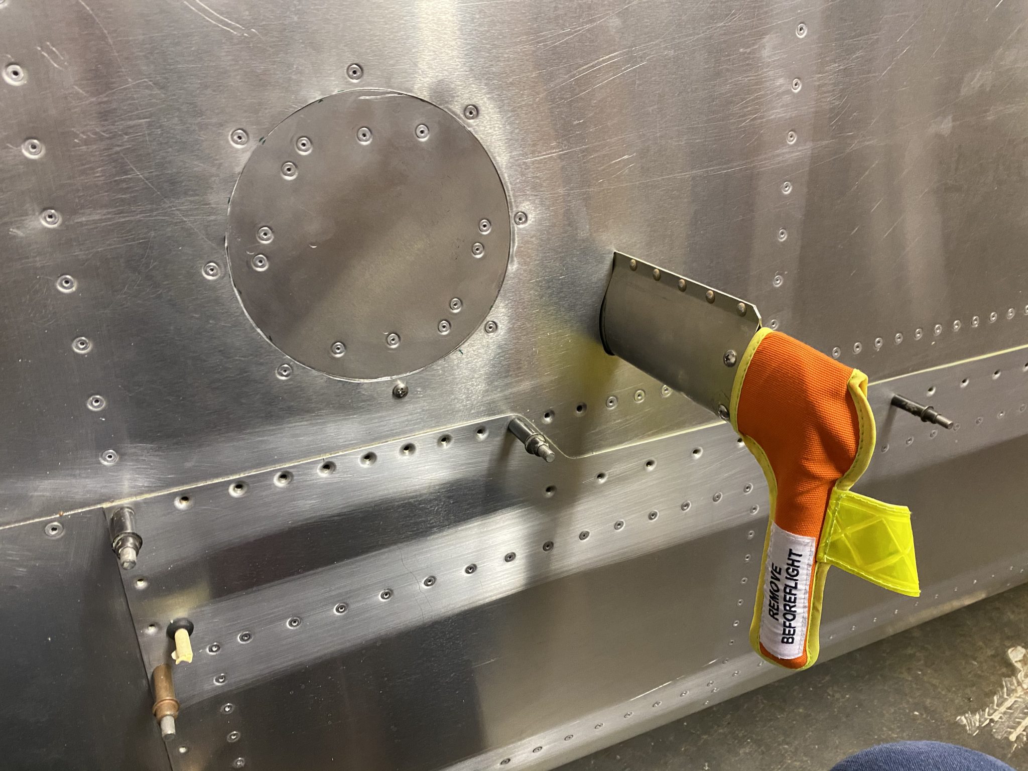
Time to finish the Pitot Tube after having cut the inspection panel hole and running the wiring a few months ago and lots of learnings about new tools, from the wiring, to flaring the tubes and connecting AN fittings.
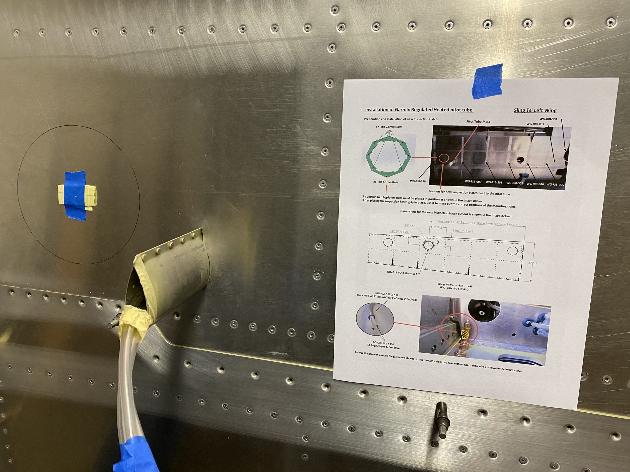
I’m using the Garmin GAP 26 heated & regulated Pitot Tube (GAP 26-20). This version automatically controls whether the Pitot Tube needs to be heated using a regulator controller that is mounted next to the Pitot Tube and will only apply heat if needed based on outside temperatures. This basically will allow me to always turn on the Pitot Tube in my panel as part of my standard operating procedures and the regulator will control whether it actually needs to be heated to prevent icing.
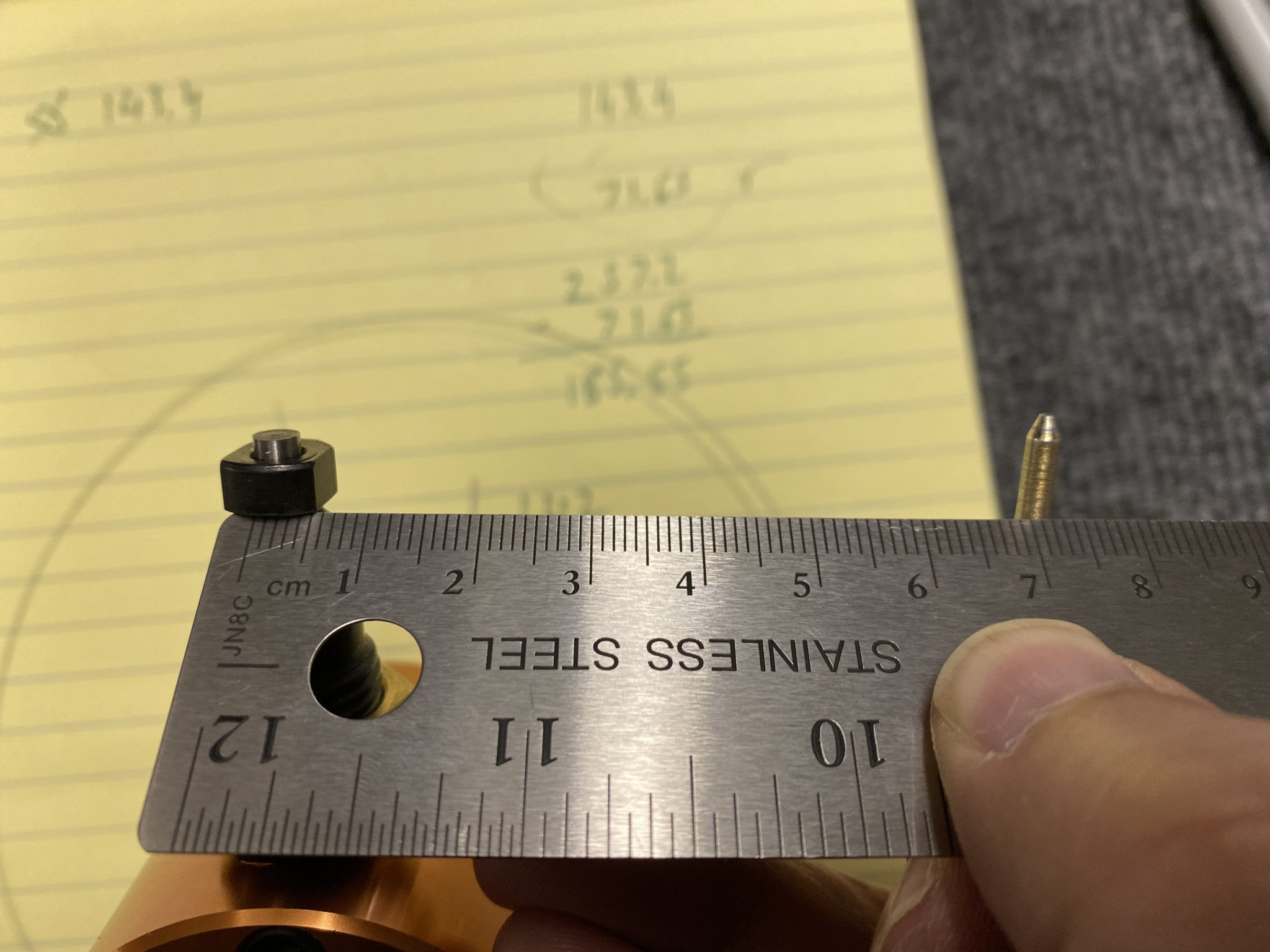
After studying the installation manual to make sure I install it correctly, I measured the tube and had to figure out how far I have to cut it in order to fit.
Fitting the Pitot Tube
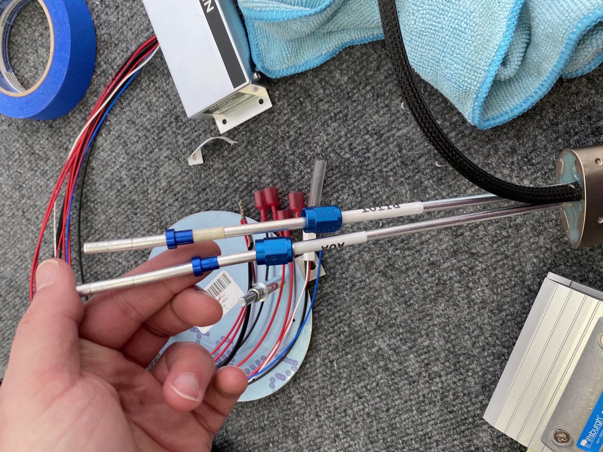
The Pitot and Angle of Attack (AOA) mast are over 12 inches out of the box, and that won’t fit. I made an initial guess and cut a bit shorter, but I was still too long so I made a series of shortenings and test attaching the fittings until I had it dialed in.
In the end, I had the masts cut down to right around 8 1/2 inches. The Garmin manual says to keep a minimum of 8 inches between the probe and transition to non-metalic tubing, so I had a little bit of margin.
Time for flaring the tubes. The AN fittings use a 37 degree flare, so I got a Rigid 377 flaring tool and a metal tubing cutter to cut the tube. Before doing this on the real Pitot Tube, I made some test flares on a spare tube I bought from Aircraft Spruce.
Make sure you put the AN fittings onto the tube before you do the flaring (I may or may not have forgotten it the first time and cut and redo the flare once).
After I had that dialed in, I did another test fit to get the length correct, accounting for the bend towards the tube and then mounted the fittings.
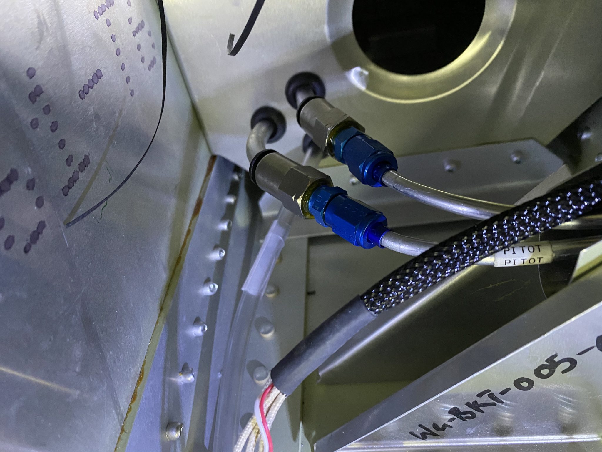
Final fit and connecting to the nylon tubes inside the wing after having cut the nylon tubes.
Installing the regulator and wiring
With the Pitot Tube itself installed, time to finish the regulator and wiring that controls the heating of the Pitot Tube.
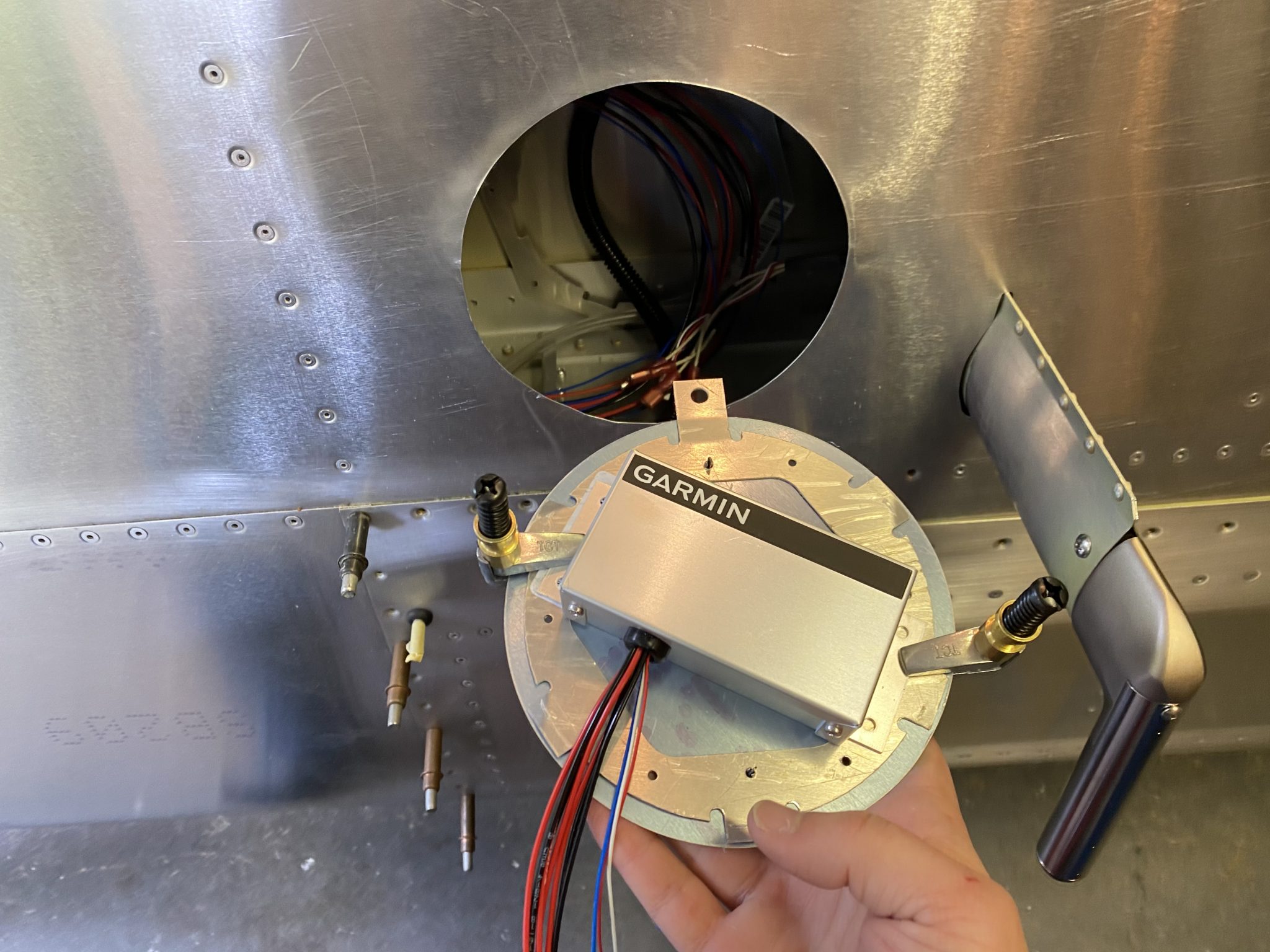
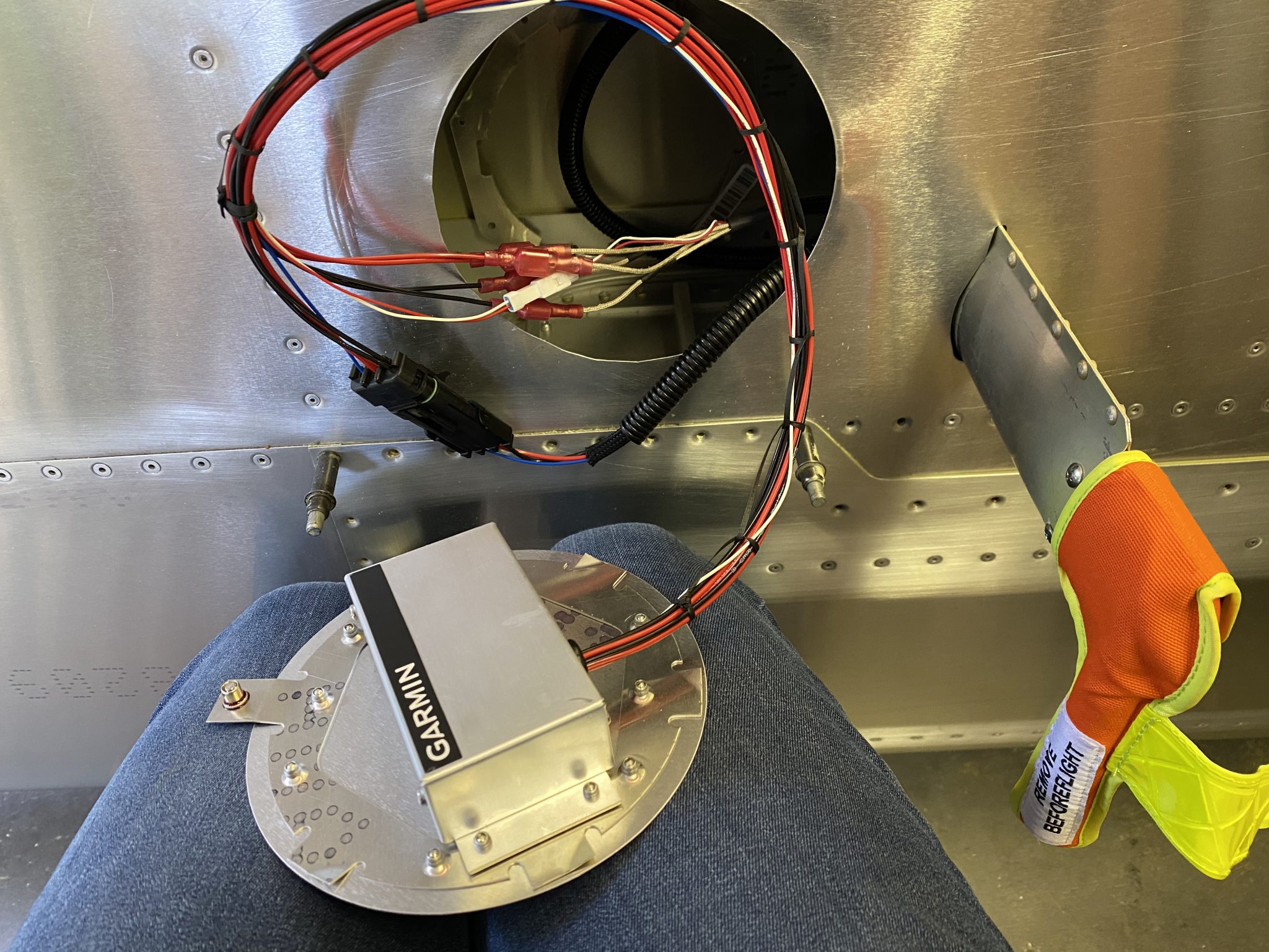
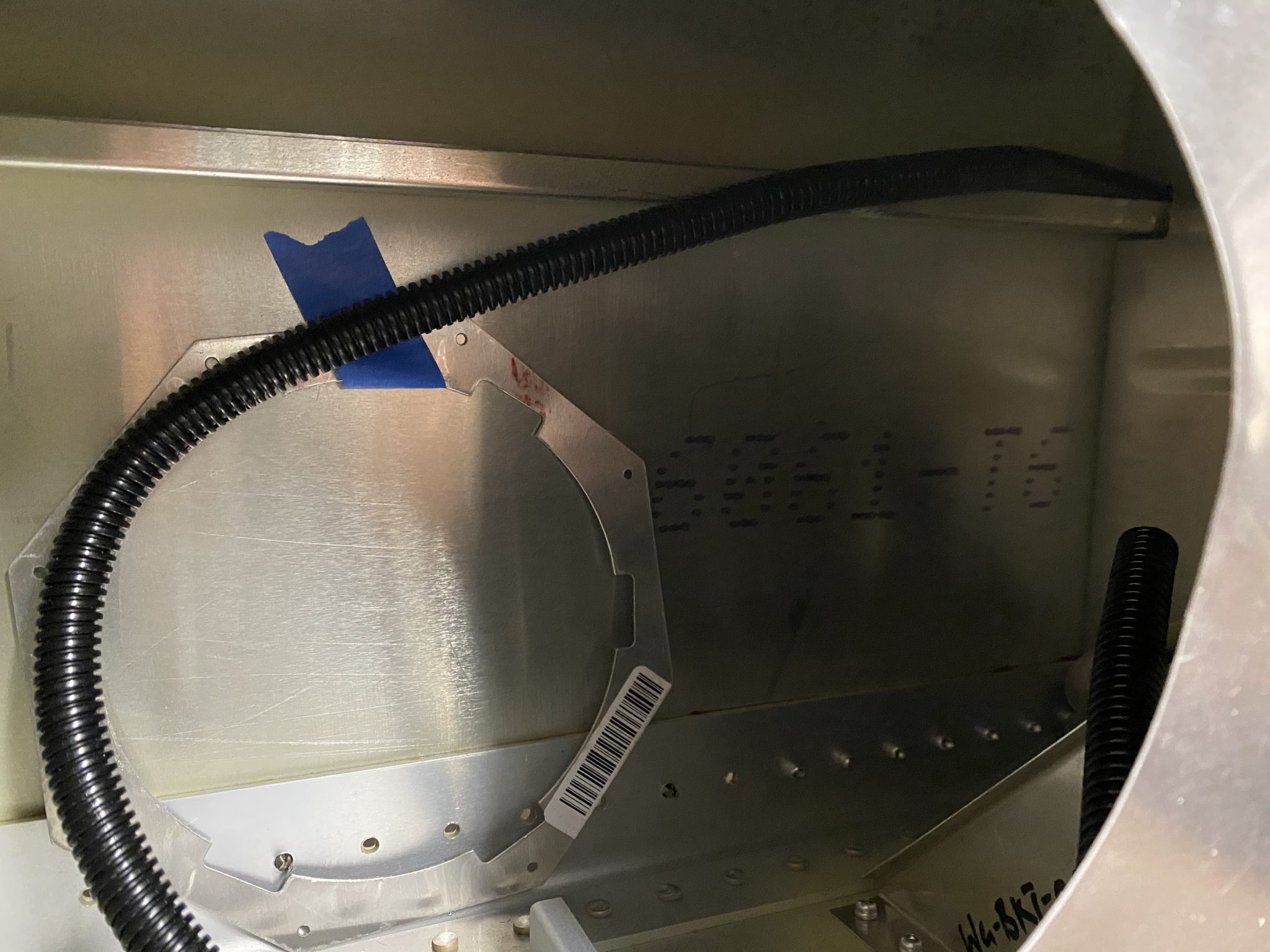
As I explained previously, I plan to mount the regulator unit onto the inspection panel plate, so I did some measuring and orienting to make sure the twist action of the round plate wouldn’t interfere with the wires coming out of the regulator.
Here is the final orientation that I figured out would work best (the screw will mount to the bottom, so the wires will come out the top):
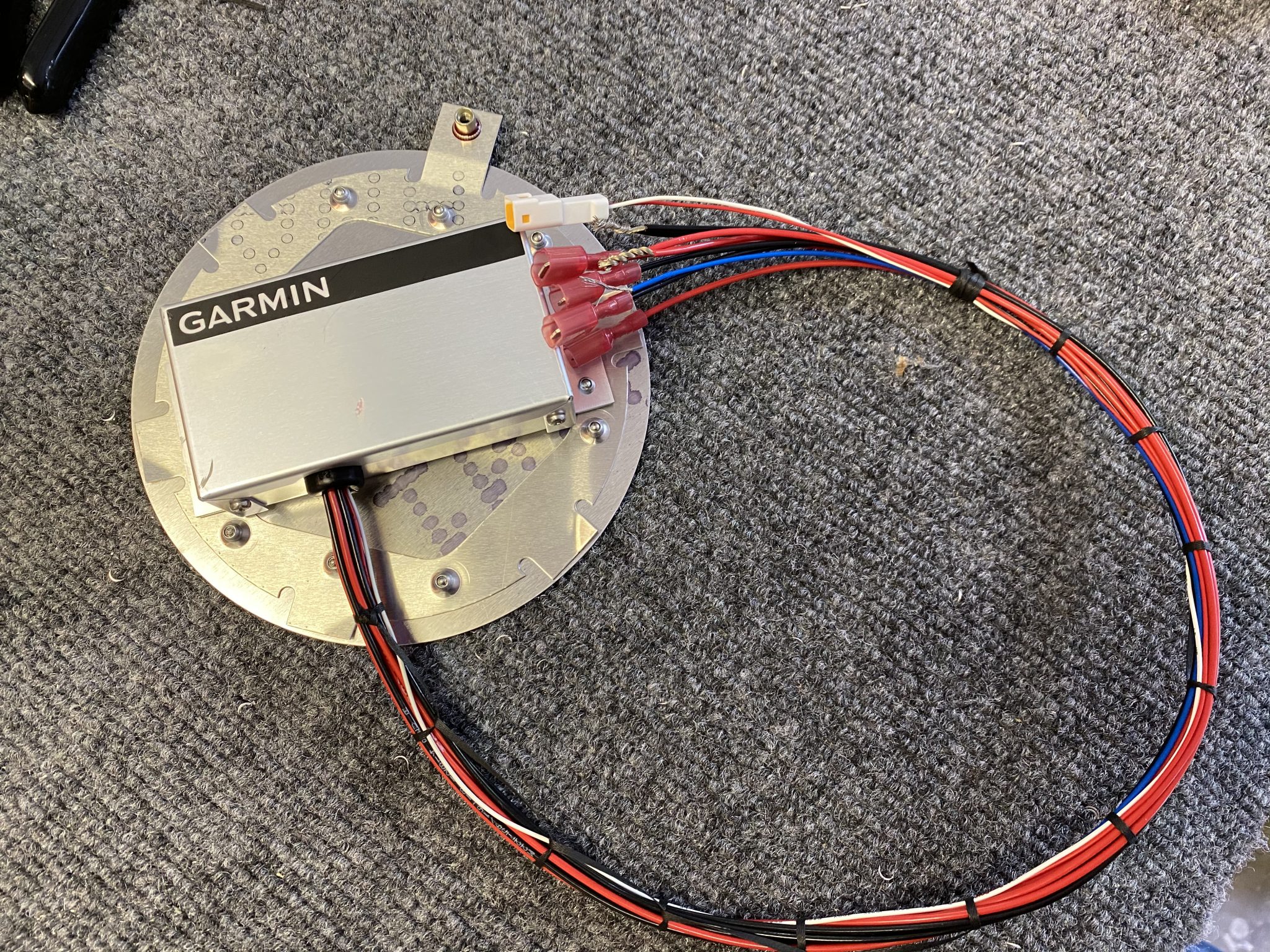
I contemplated between screwing or riveting it on, but I figured that it’s unlikely that it will need to be changed out frequently, so I riveted it onto the plate.
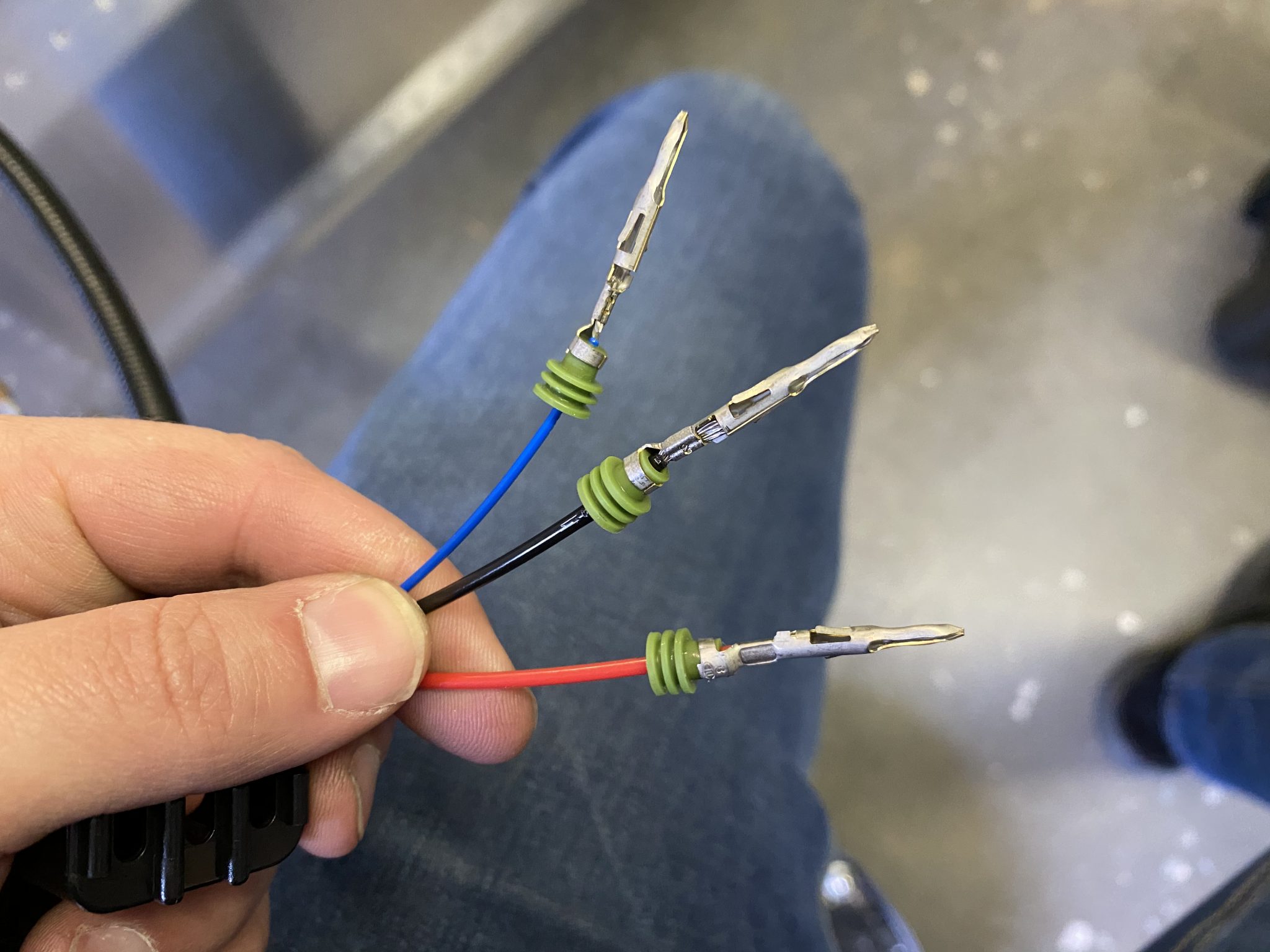
The last part was to create a connection from the regulator to wires I ran through the wings. I used some weatherpack connectors for this, which create a waterproof connection and a solid crimp, similar to the Delphi GT 150 that Midwest Panel uses to connect the wiring harness.
Final completed connection between the regular, the Pitot Tube and the wires running to the center.
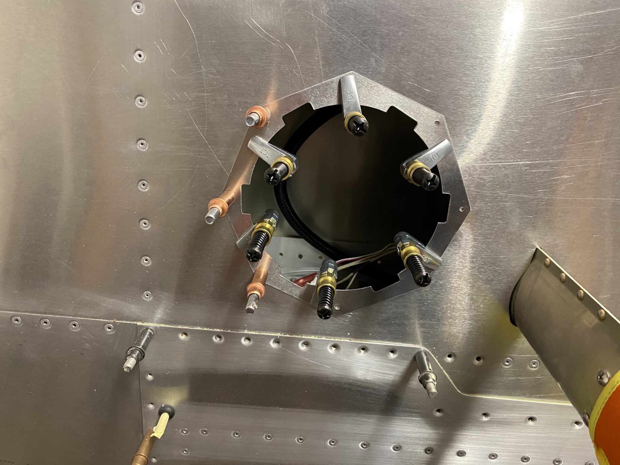
Installing the plate to the wing
The last and final part of the installation was to mount the inspection panel plate onto the wing. I did this last to prevent scraping up my arm while I had to do all the mounting inside the wing, since the backing plate that holds the plate in place has a series of pokey corners that love to eat airplane builder blood.
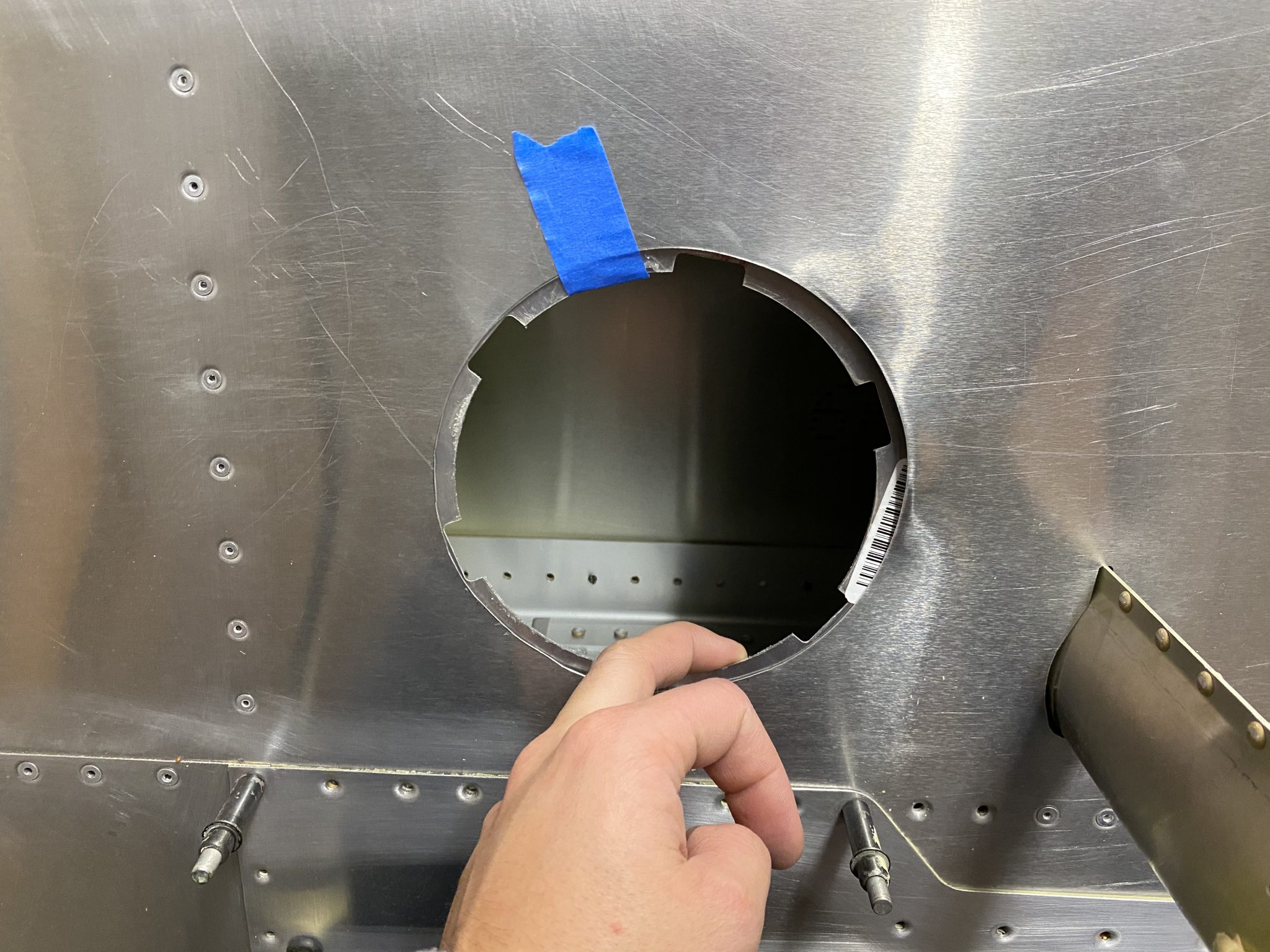
First I lined up the plate with the wing and then did the match drilling of the holes:
The I dimpled the plate and the matching holes on the wing and riveted it in place.
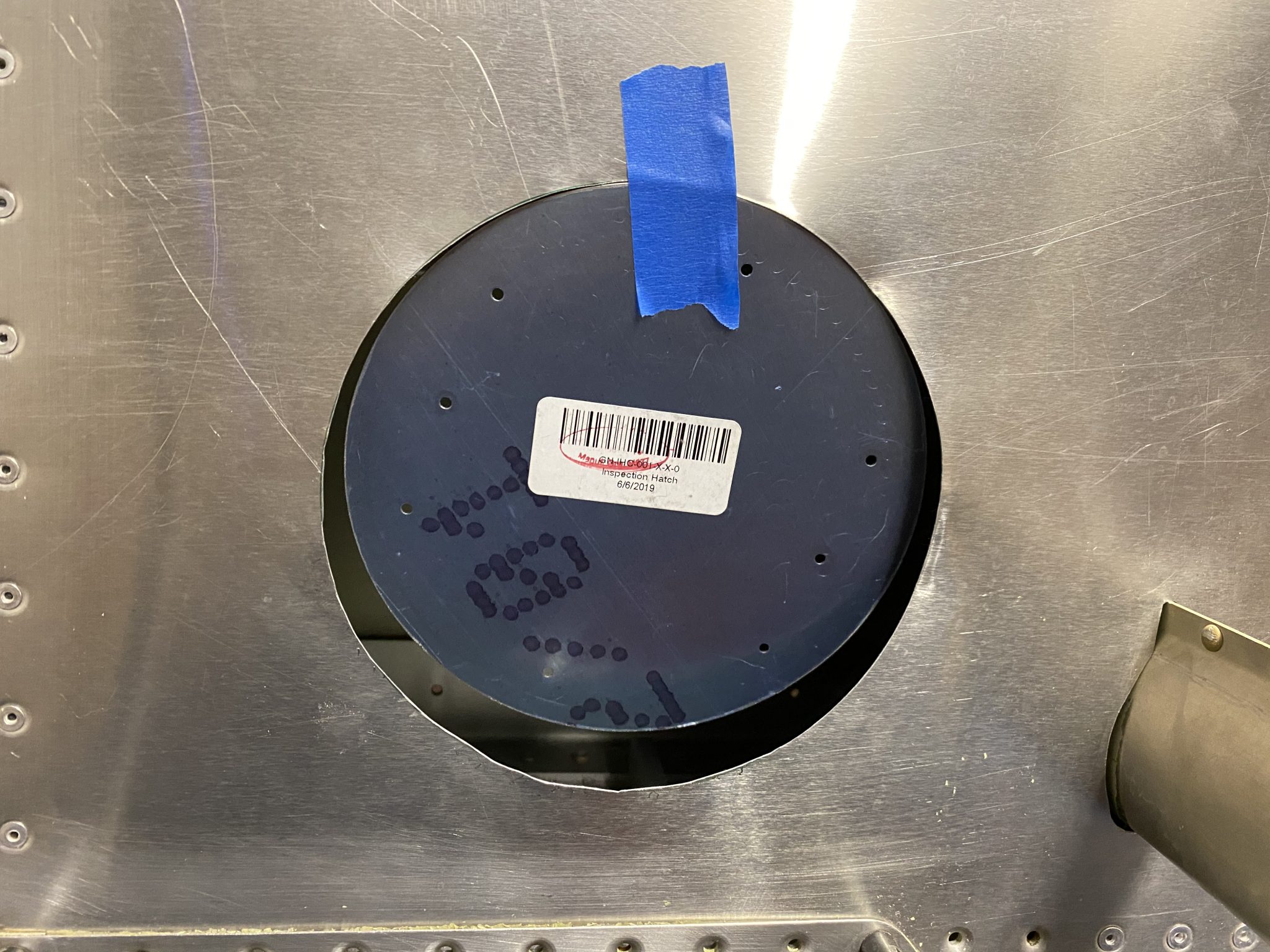
And here is the completed and closed up Pitot Tube and Inspection Plate that holds the regulator:
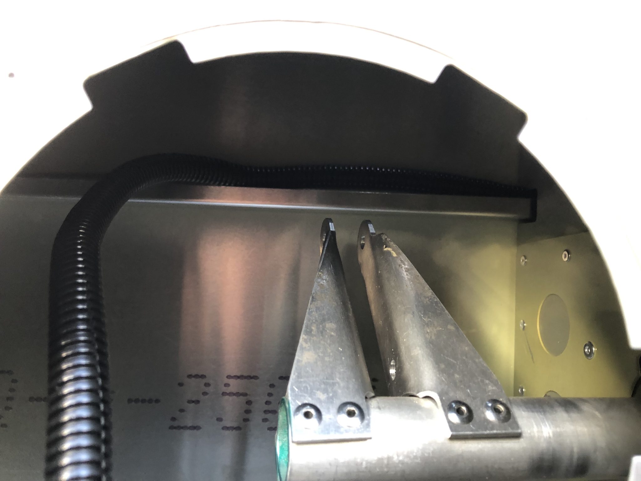
I figured out where I want to run the wires a while back after some tinkering and I am using one of the strut channels for the length of the wing, except the very end at the wing-walk where I had to make one curve down the bottom.
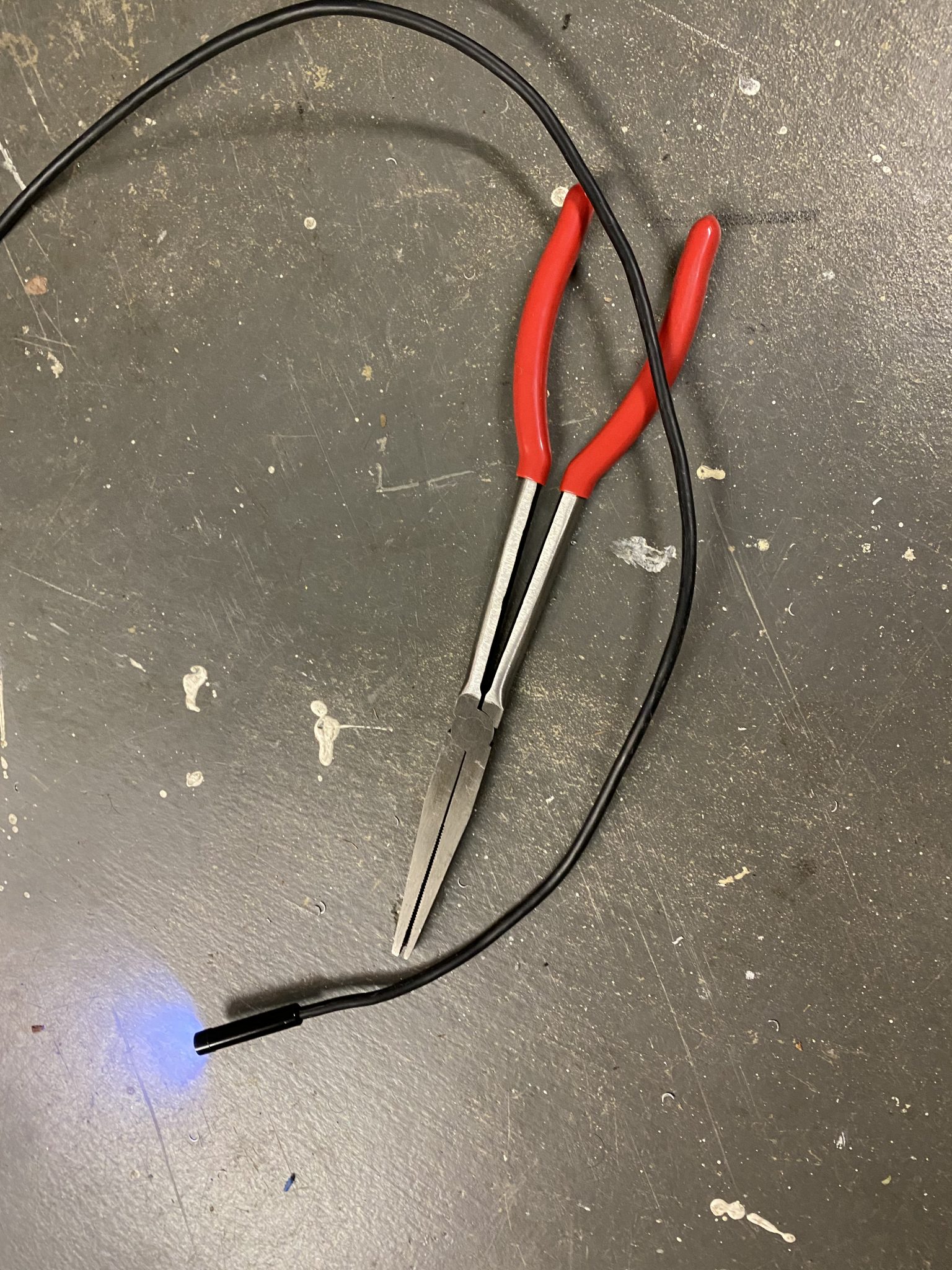
The hardest part was figuring out a good way to come out the bottom where the wing-walk is, since the strut channel doesn’t go through there. On the last picture above, you can see when I finally managed to grip on to where I want the loom to come out of with the help of some duckbill pliers, which were a suggestion from my EAA chapters Technical Counsellor when he visited a few months ago.
Running the wire
With the question of where to run the wire solved, onto actually running the wires.
I am installing the Garmin GAP 26 Heated/Regulated Pitot Tube, which comes with a Regulator that needs to be installed next to the Pitot tube and controls whether the Pitot tube actually needs to be heated.
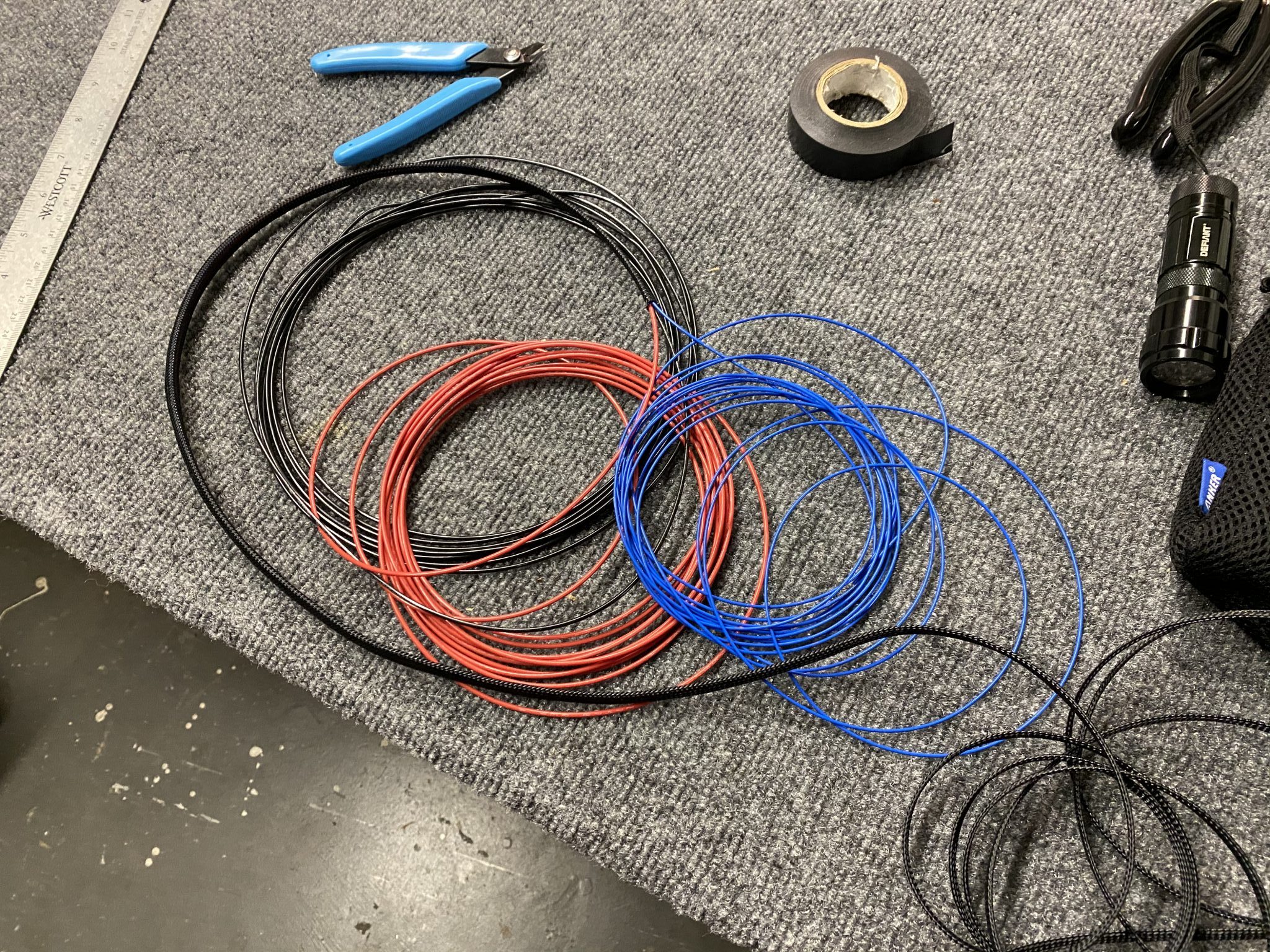
For this, there are three wires to run – two for the power and one for the discreet output, which integrated into the Garmin G3X Panel to show when the Pitot Tube is actually heated.
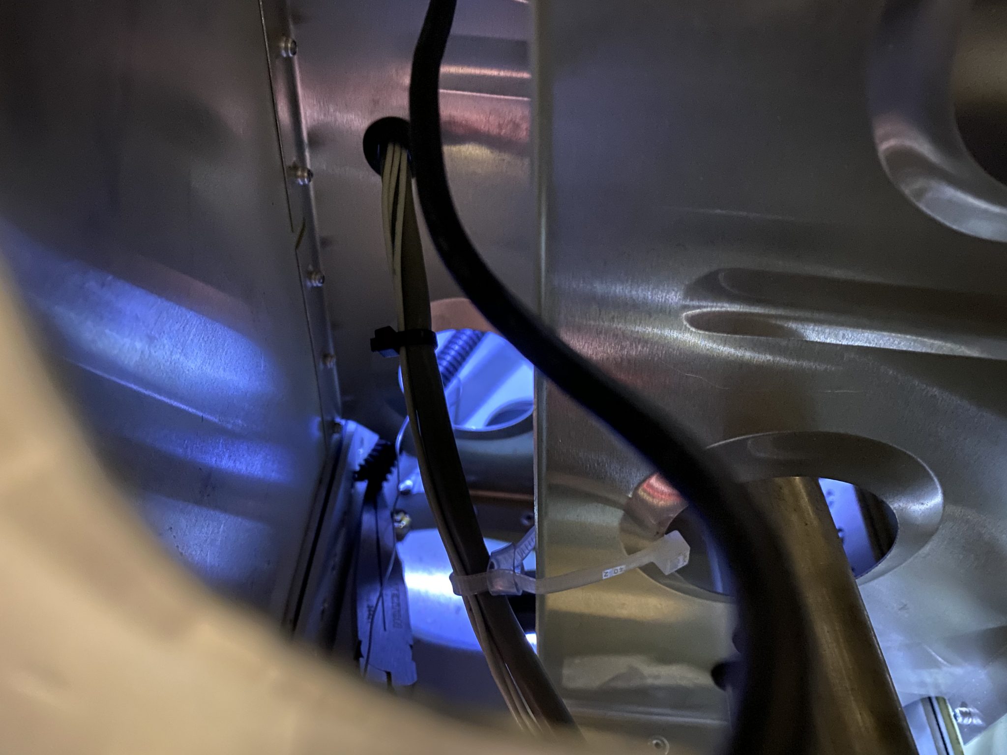
I ran the three wires through some braided sleeving to give them some extra protection and make running them through the wire channel easier in one go.
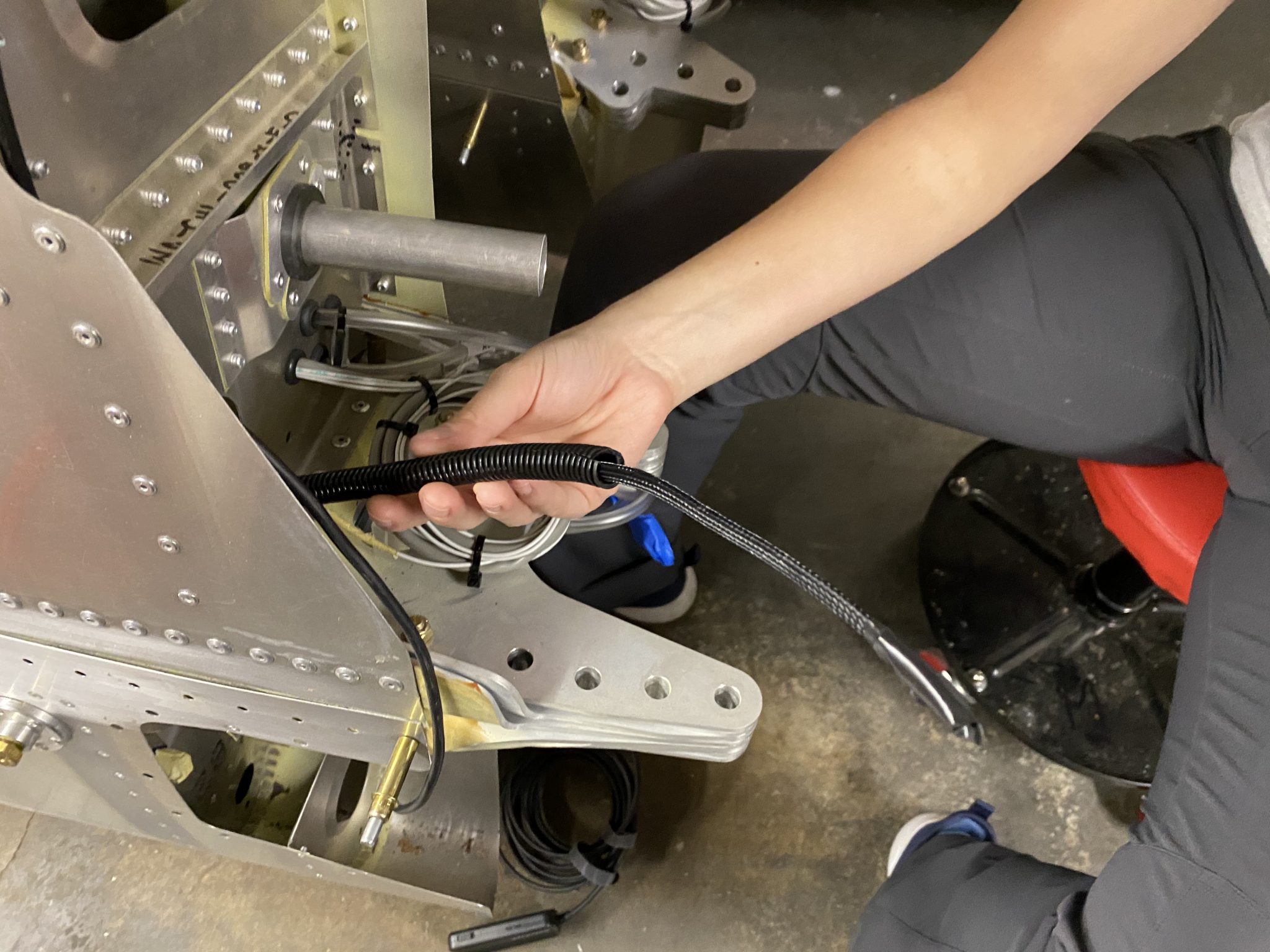
With that out of the way it “just” took a lot of back and forth, more use of the Endoscope and the thin arms of Juliana and repeated shouts of “push, push” and together we managed to run the wire all the way. She cheerfully pronounces “Congratulations, it’s a wire” as it came out the other end.
I was planning to finish to Ailerons, but unfortunately in my final prep, I realized that I received two right side balance tubes instead of a left and a right one. The missing tube should be here sometime next week, so until then, the Ailerons are on pause.
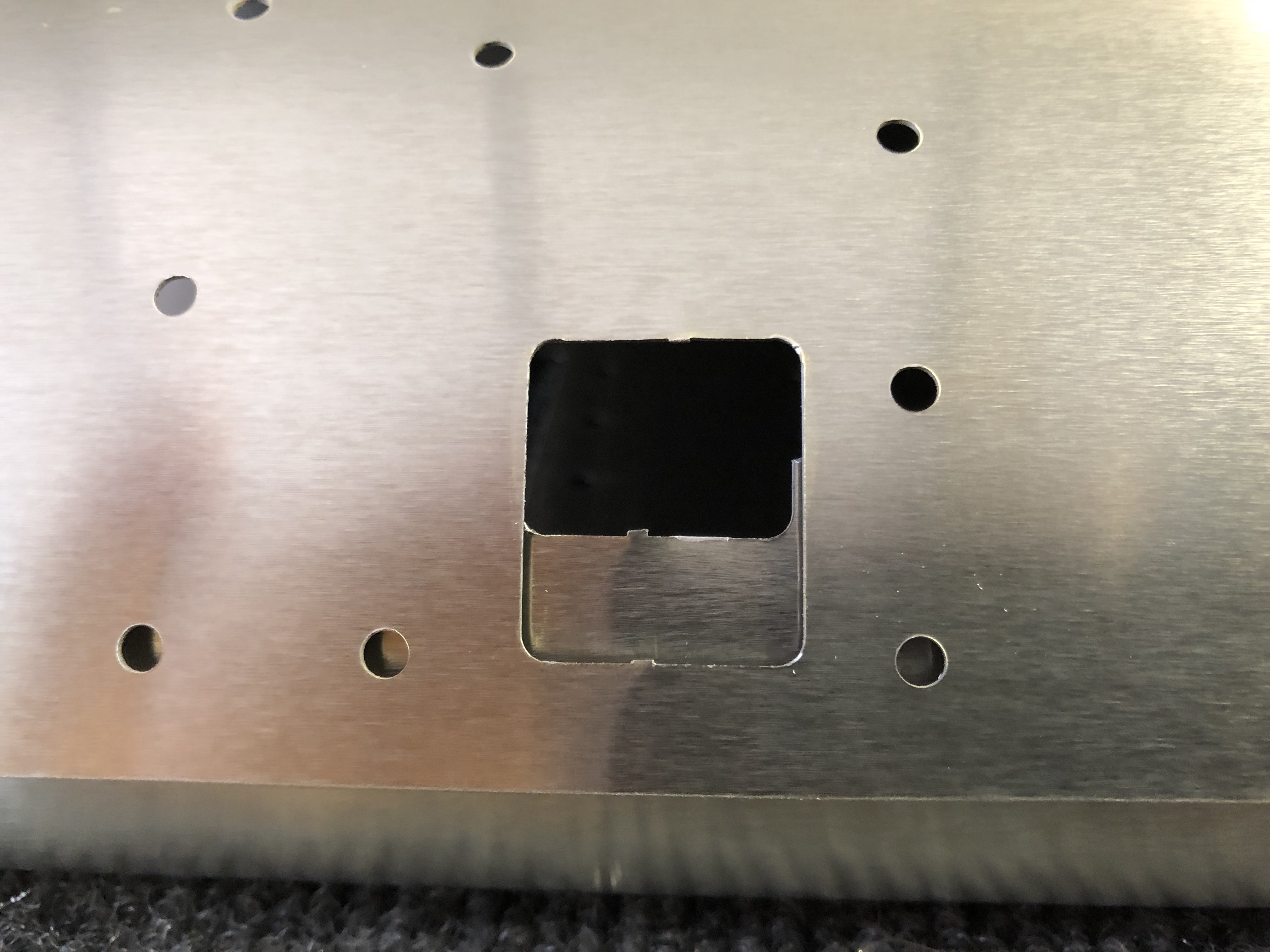
This gave me some time to finally make the big step of cutting out the hole in the Wing for the Pitot inspection panel. I received the heated & regulated Garmin Pitot tube from the Factory and verified that it will fit nicely on the back of the round inspection cover, so I will mount that and I can keep my square inspection panel I designed for some other time.
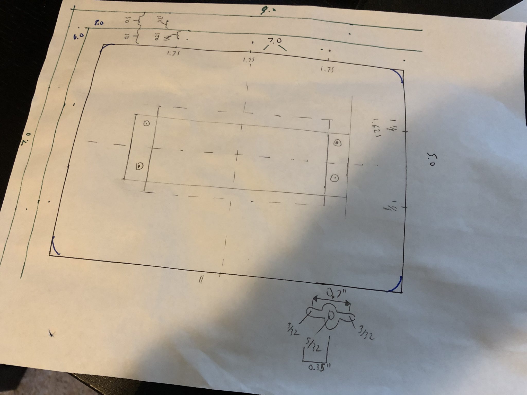
First I did a lot of measuring and marking based on the plans. Since this is truly a moment of measure-twice, cut-once I measured and re-measured a few times.
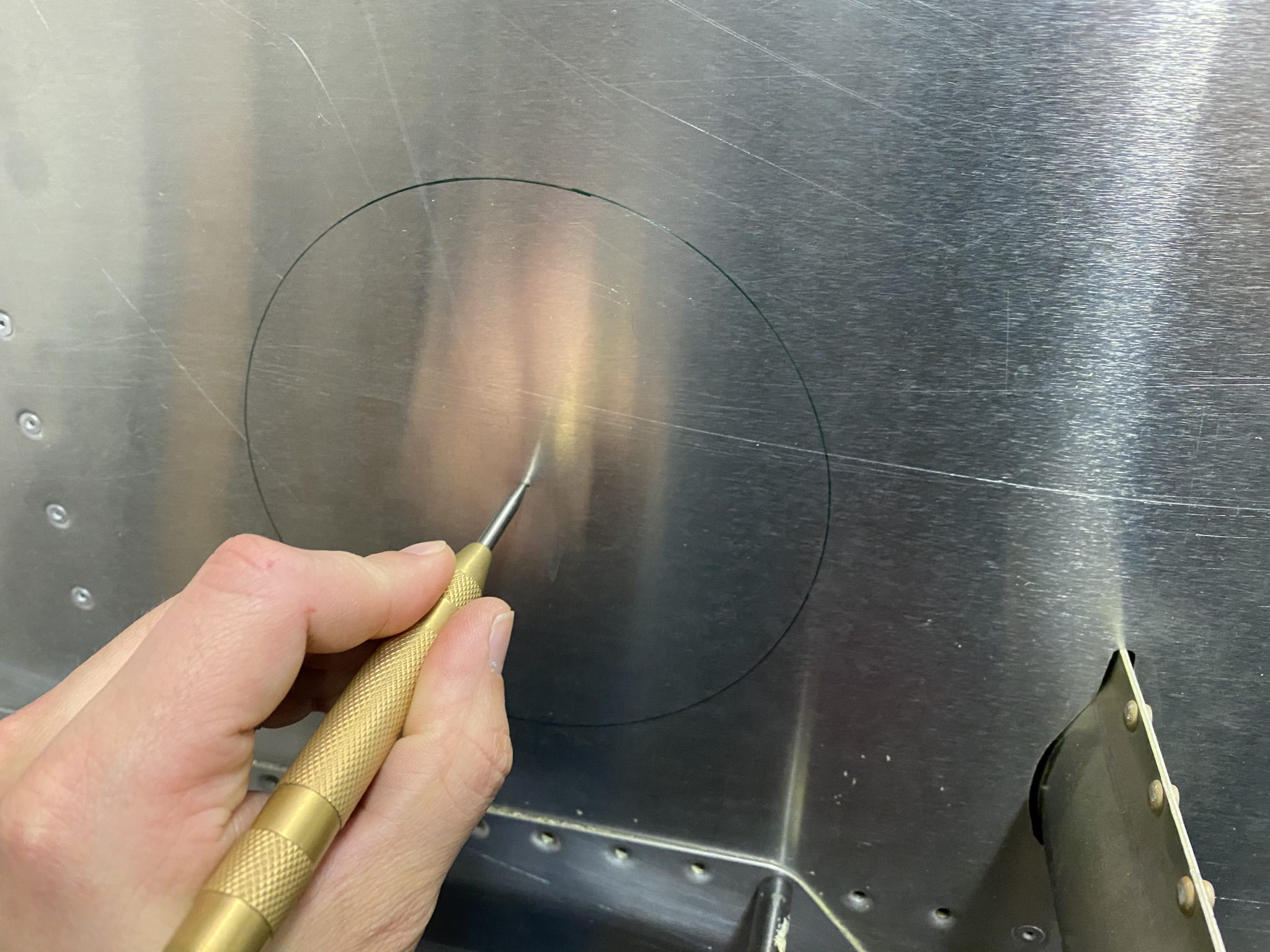
With all the marks in place, I started with cutting the pilot holes for the center mark and the cutting head.
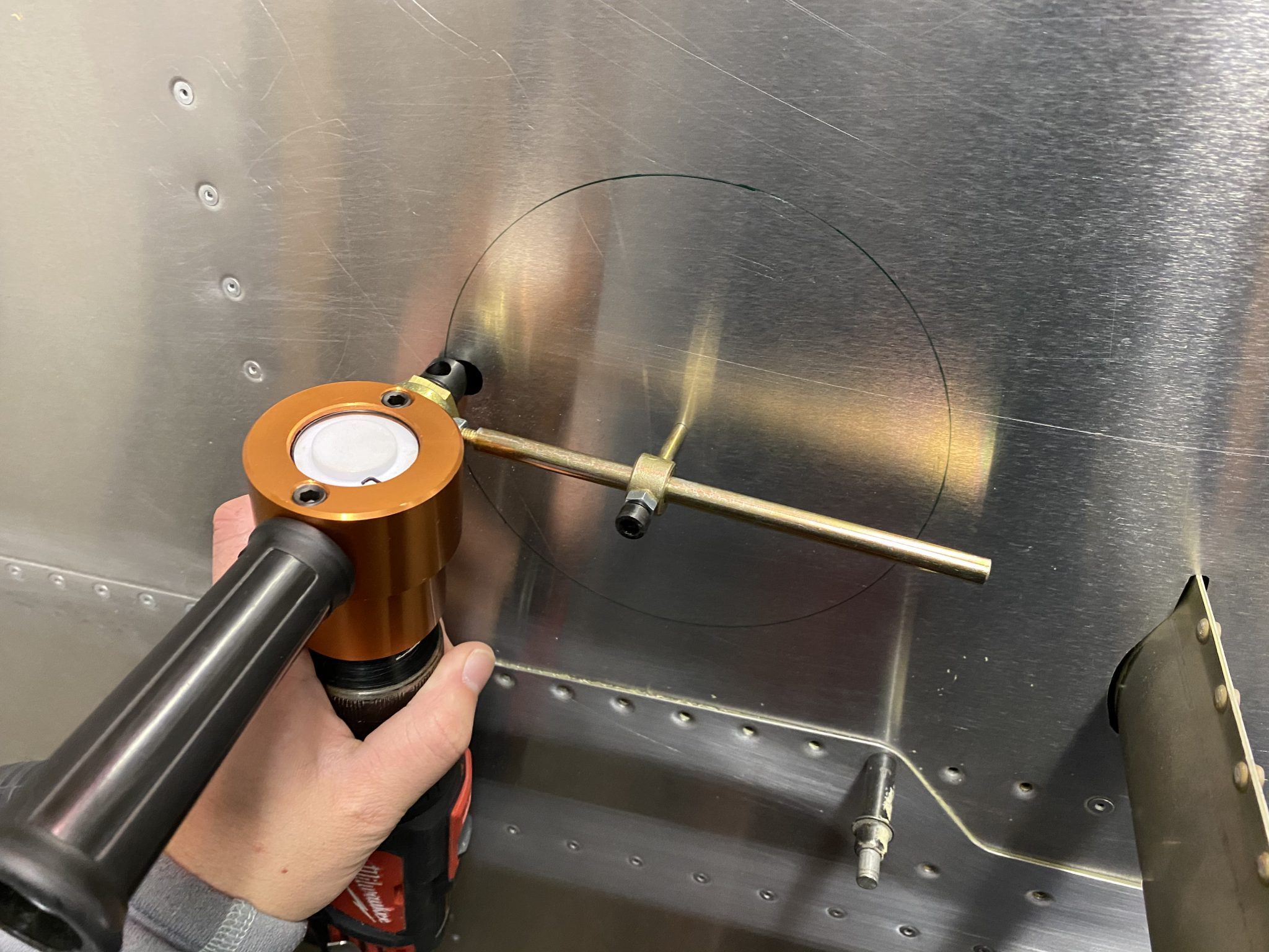
The final moment of truth – Time to cut the hole for the inspection panel using my nibbler cutting tool.
I cut the first half of the circle and then reversed the tool since the Pitot tube mast was in the way of completing the cut in one direction.
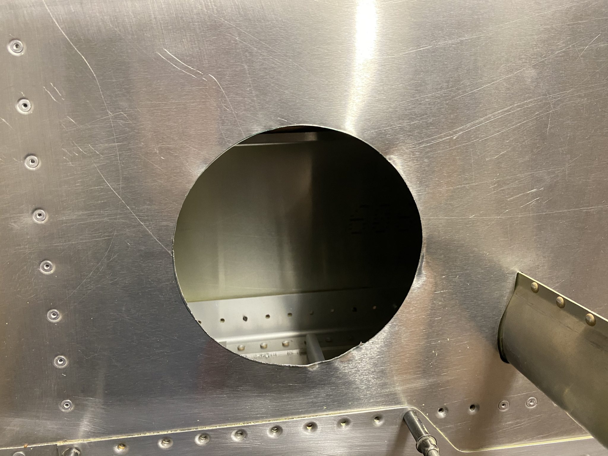
The cut came out pretty well and I just had to do a little bit of sanding to smooth the edges.
I prepared most parts of the Aileron a good while ago, but I was missing a replacement for one set of ribs that were damaged, so I had put the Ailerons aside and finished the Flaps and Elevator in the meantime.
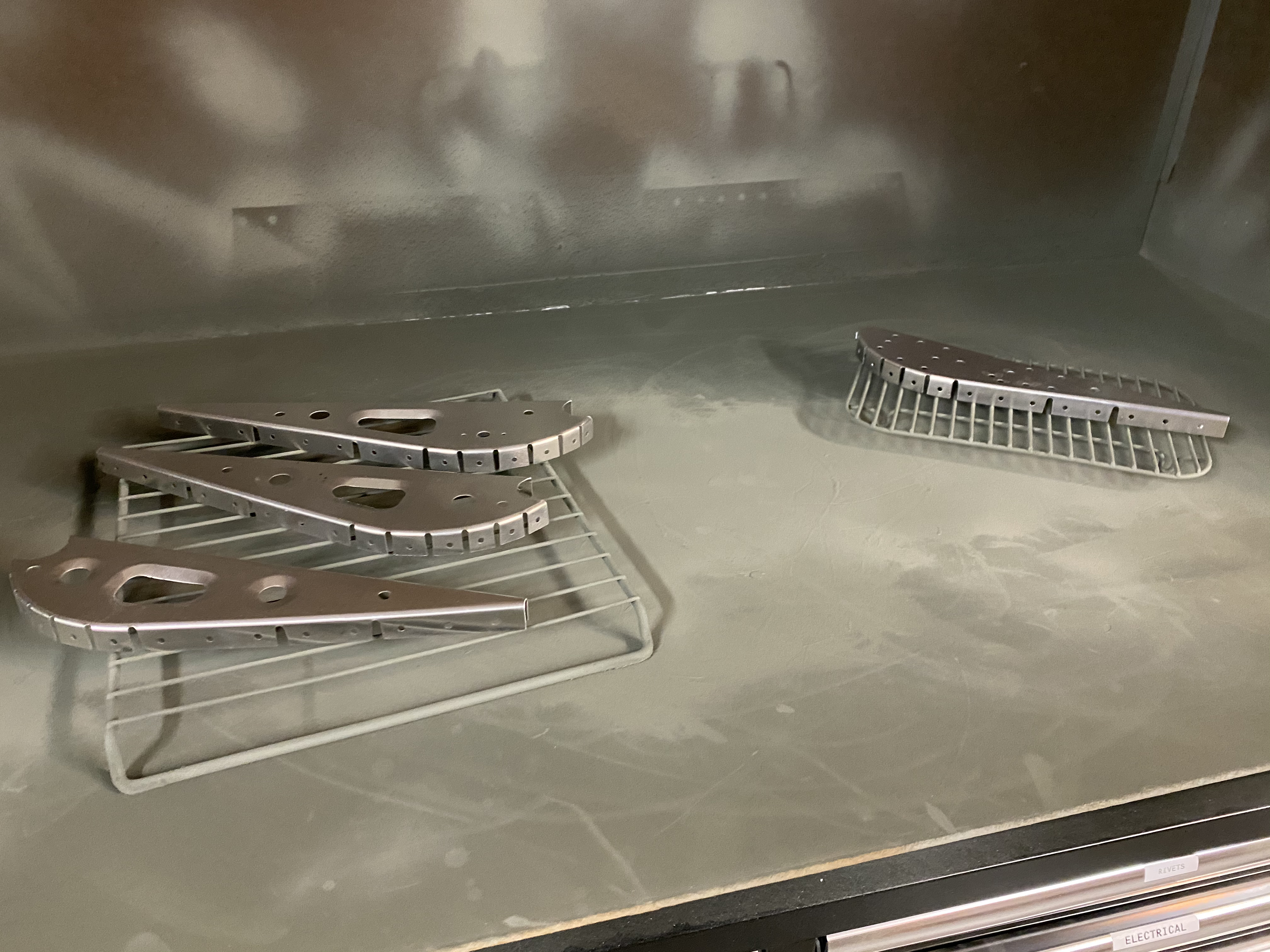
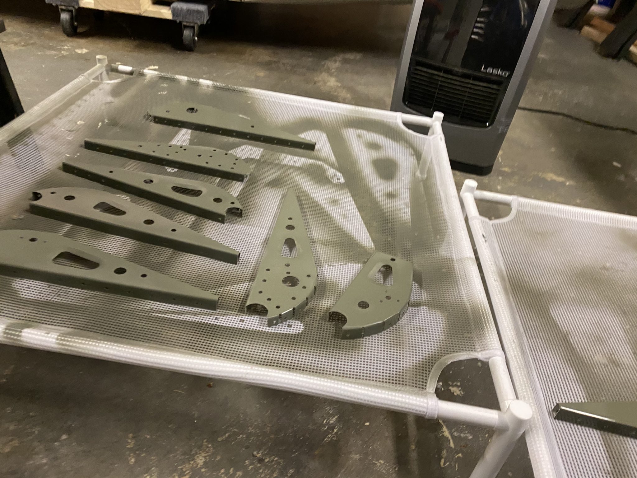
Now with the Elevator done and the replacement ribs in hand, back to finishing up the Aileron. After a quick inspection and deburring of the new rib I laid out all the parts and got out my small painting booth to prime the ribs.
Once the primer is set I can get onto assembling everything and riveting the Aileron.
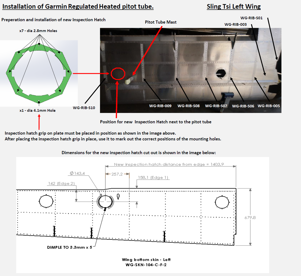
One of the things that the factory forgot as part of the change from the Sling 4 to the Sling TSi was the required access to the internals of the wing next to the Pitot tube.
In the Sling TSi design, some inspection panels were removed including the one next to the Pitot tube. By itself, if someone was building the wings from scratch, that might be fine as long as the builder installs the Pitot tube beforehand and doesn’t anticipate to ever need to access it, such as if using an unheated Pitot tube.
However, I am going to use the Garmin heated & regulated Pitot tube, which not only requires wires to be run to the Pitot tube, but also that I need to mount the regulator unit next to it.
Since I ordered the quickbuild, I ordered it with this specification, but unfortunately the factory didn’t receive the Pitot tube from their supplier in time and shipped my kit without installing it.
So after I received my shipment and inspected everything, I realized that installing this after the fact wasn’t going to be easy, particularly with the lack of a hole in the wing. Unfortunately the factory also forgot to run the wiring to the pitot tube, which creates a whole second issue, for which I’ve been working on a solution.
I informed the factory a while ago and also gave Matthew, one of the other TSi builders a heads-up since he hadn’t started on the wings yet. The factory realized their mistake in the plans and promised to come up with a solution and send me instructions and a plan.
Drafting a plan
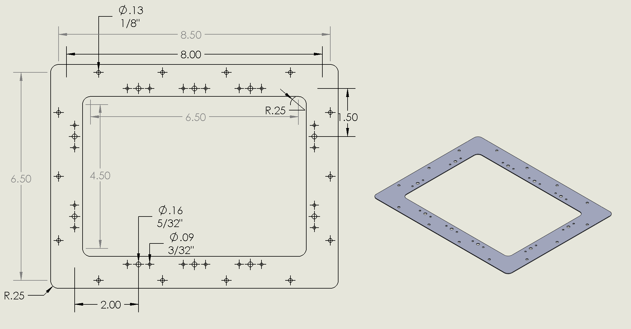
While I was waiting for the factory to come up with a plan, I actually started drawing up my own plans to fabricate the entire inspection panel myself and used it as an opportunity to learn and use Solidworks, which I can use for free as part of being an EAA member.
Since I had the chance to chat with Mike Blyth at Oshkosh for a while and we chatted about my build, I mentioned that I was still waiting for the factory to come up with a plan for the inspection cover and he promised that he’d check on the progress when he got back to South Africa and indeed, two weeks later, I got an email with the plans.
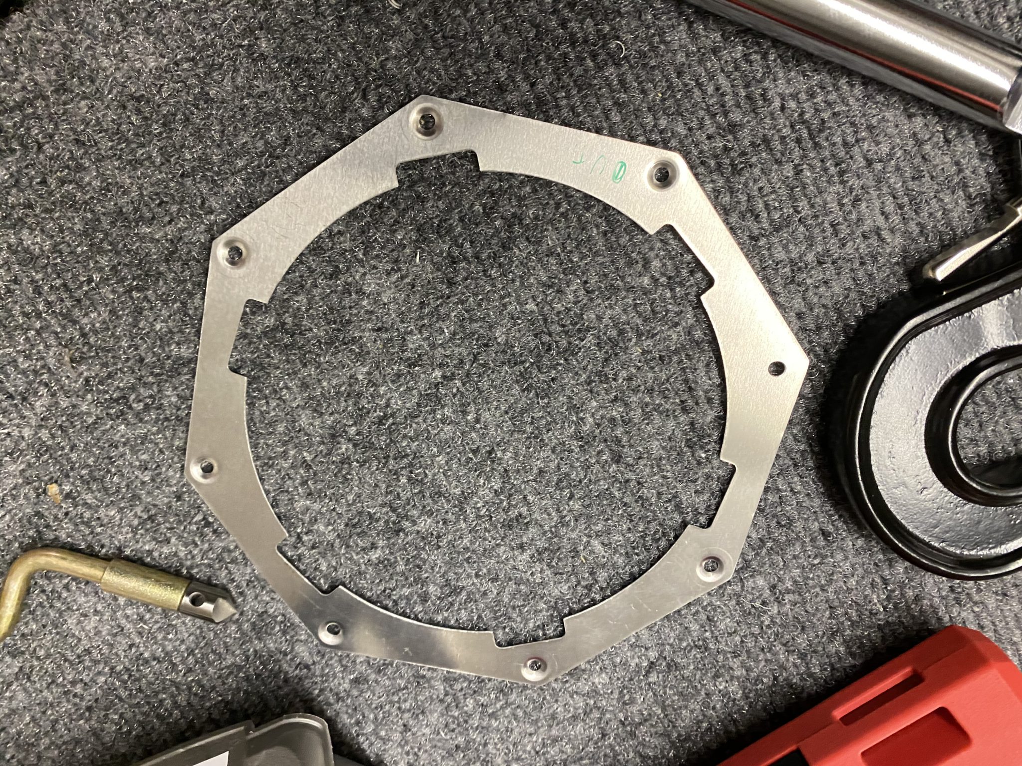
The factory plans, in keeping with the other inspection access panels, uses the same flush round inspection cover that is used to access the Flaps and Aileron connecting rods.
Since I am still busy with other things in the build and haven’t actually made my own panel yet, I am going to go with the factory plans that they have drawn up for me.
Cutting a round inspection access panel hole
There is just one difficulty to overcome – the access panel is round and large and I don’t think there are 143.4 mm drill bits I can buy in Home depot.
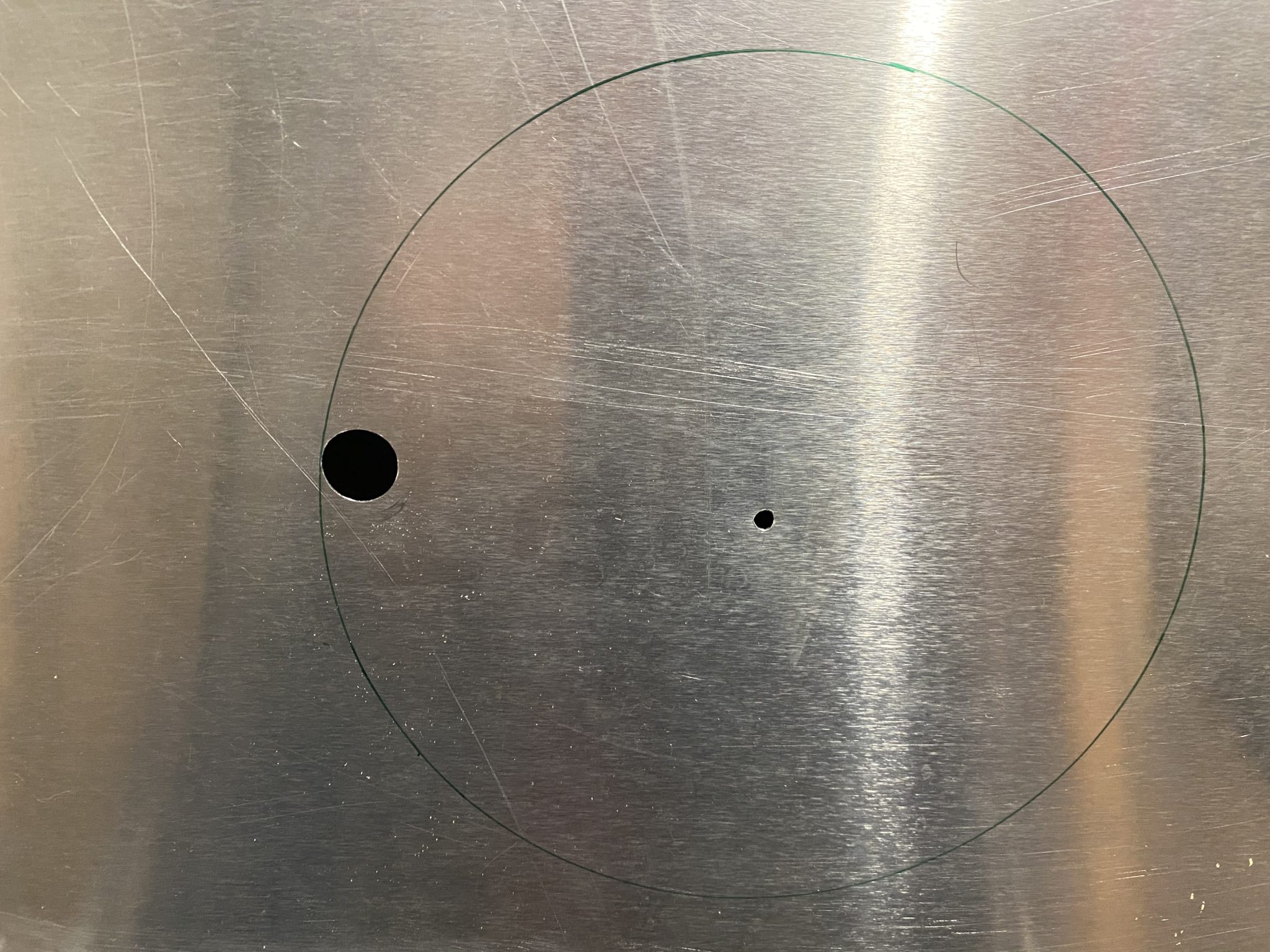
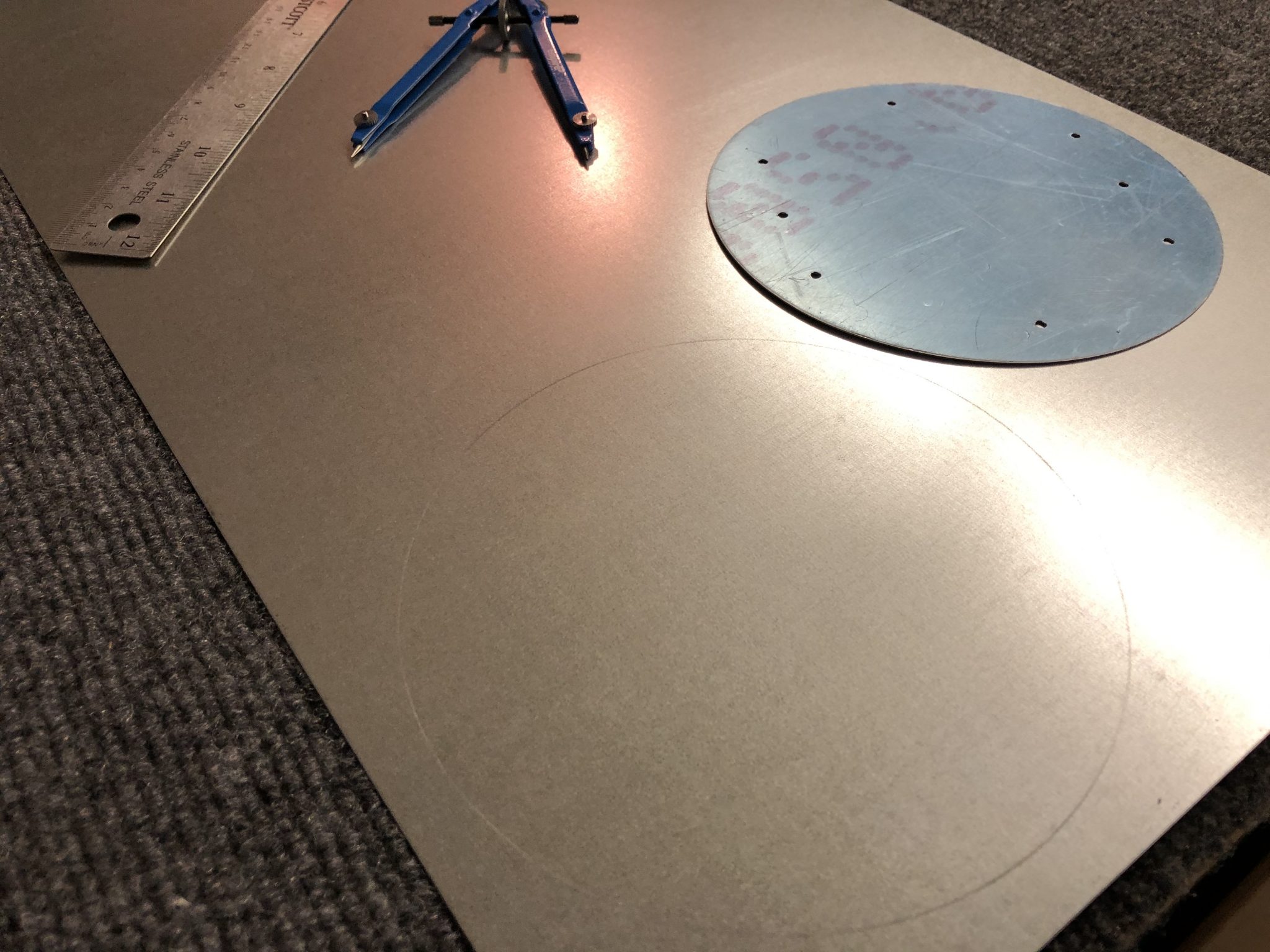
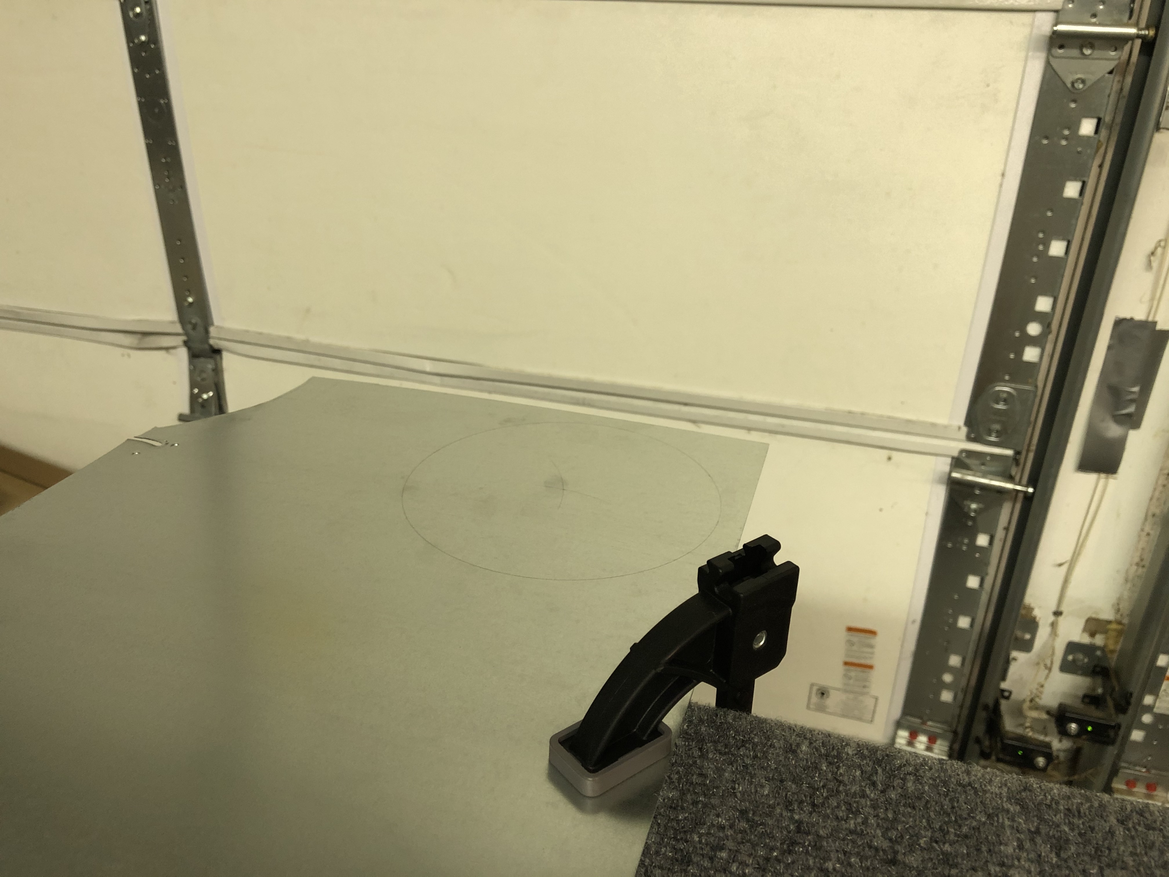
Since this is quite an operation, I decided to get some practice with the tool on a piece of spare aluminum and also made a video of it, since I figured that it might be helpful for other builders in the future.
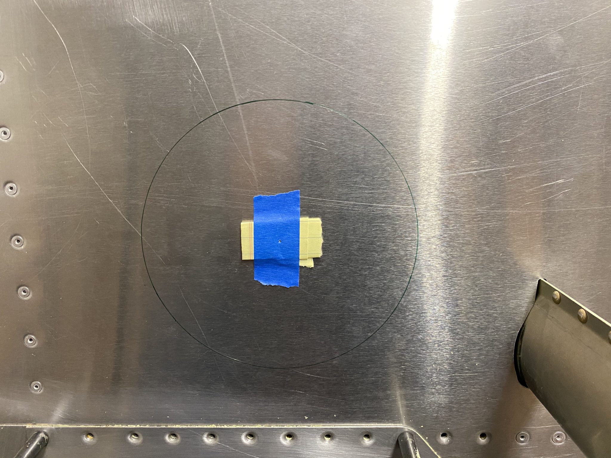
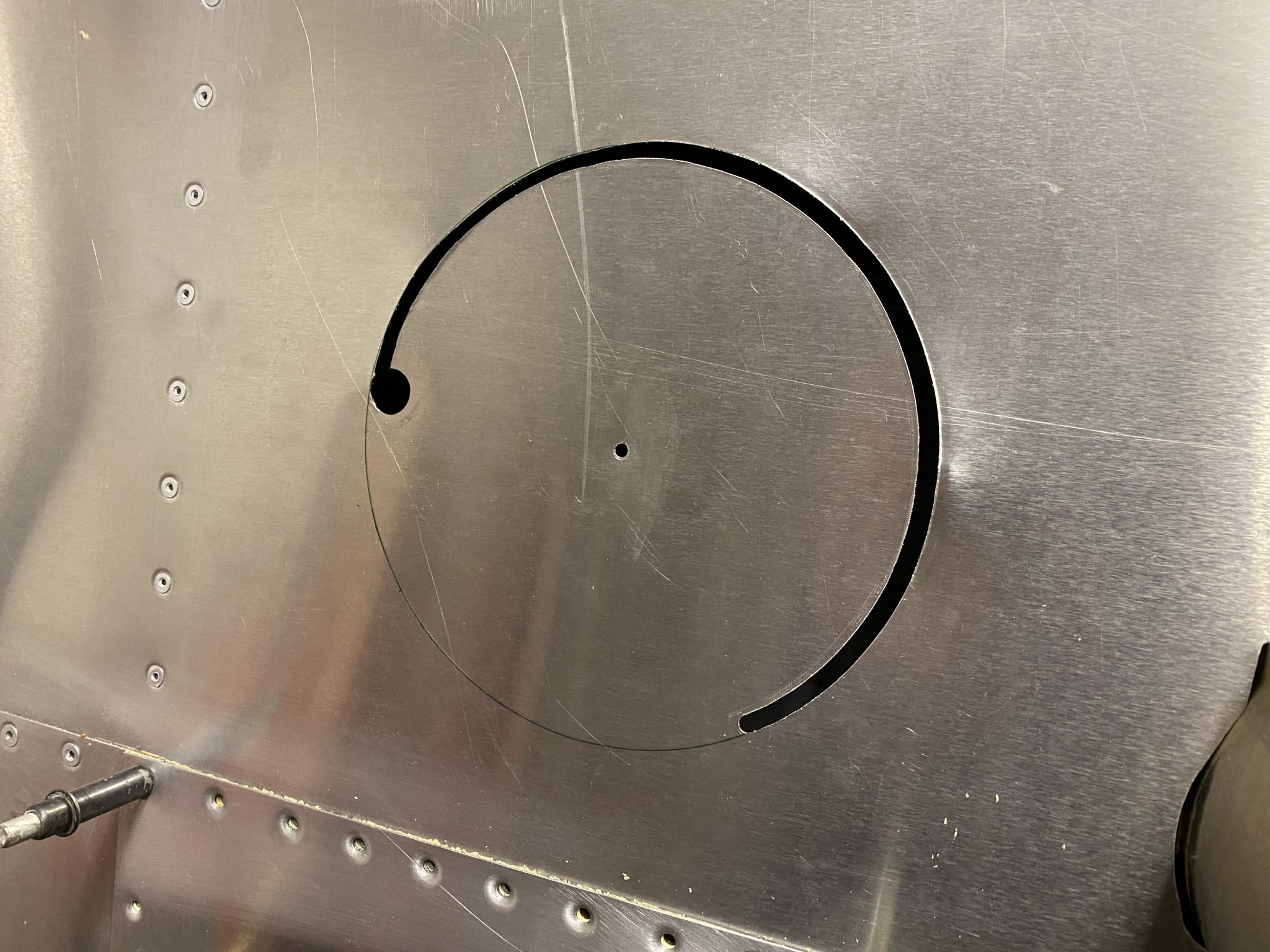
I started by marking out the circle using a drafting compass. It’s been quite a few years, but luckily I still remembered how to use it and how to find the center of the circle again by making two marks. Proof that you may indeed use what you’ve learned in geometry class sometime in life, even if it’s 15 years later. After that I clamped the piece of metal on the edge of the table.
I drilled the center pivot hole to 1/8th of an inch, which makes the pivot sit in the hole and then measured out the starting hole for the drill, make a starter hole and then used a step drill bit to upsize the hole until it aligned with my marked circle.
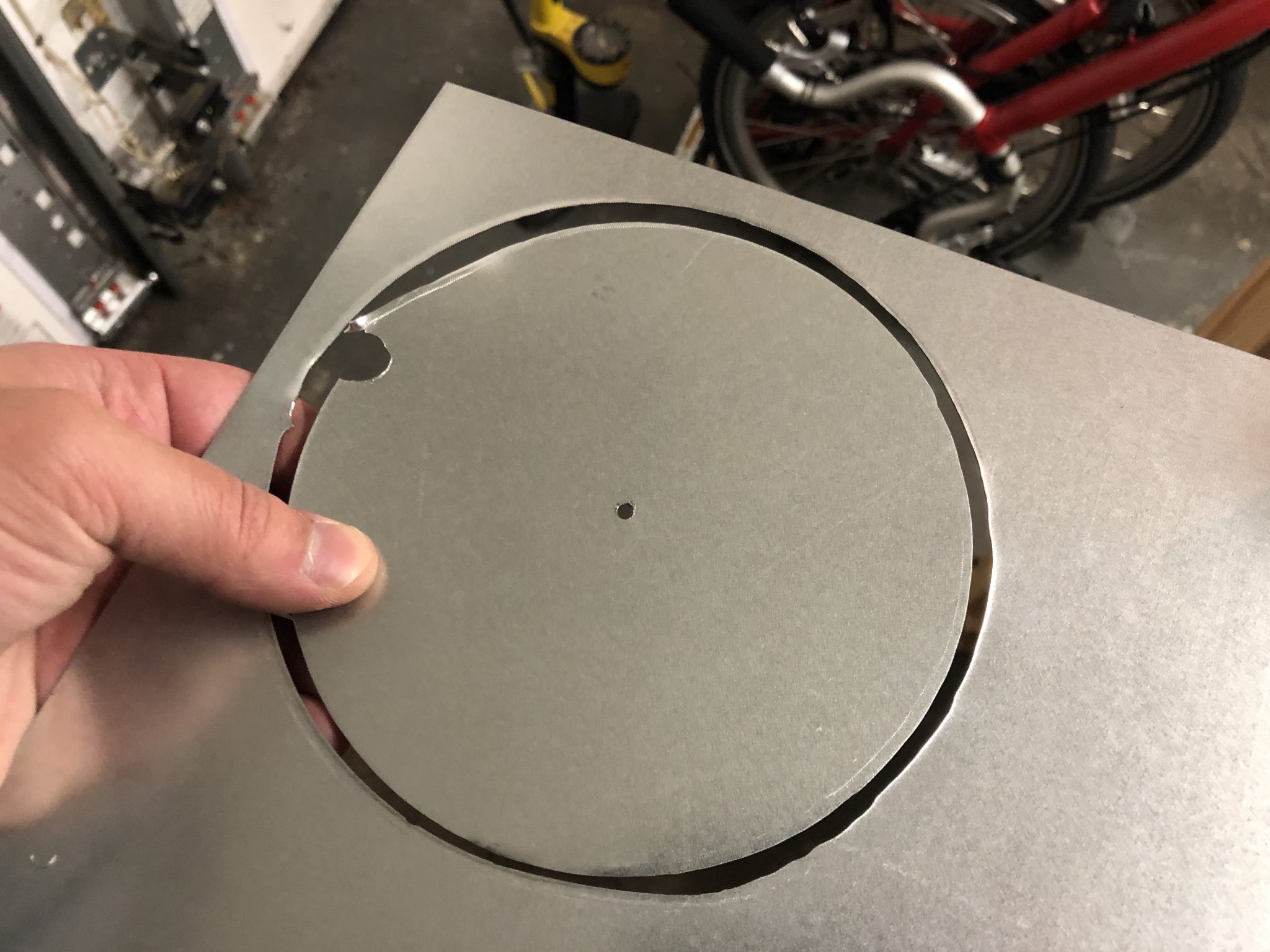
After that, I set up the drilling tool with the pivot and made sure that the outside of the cutting bit aligns with my circle and then attached the drill and went to work.
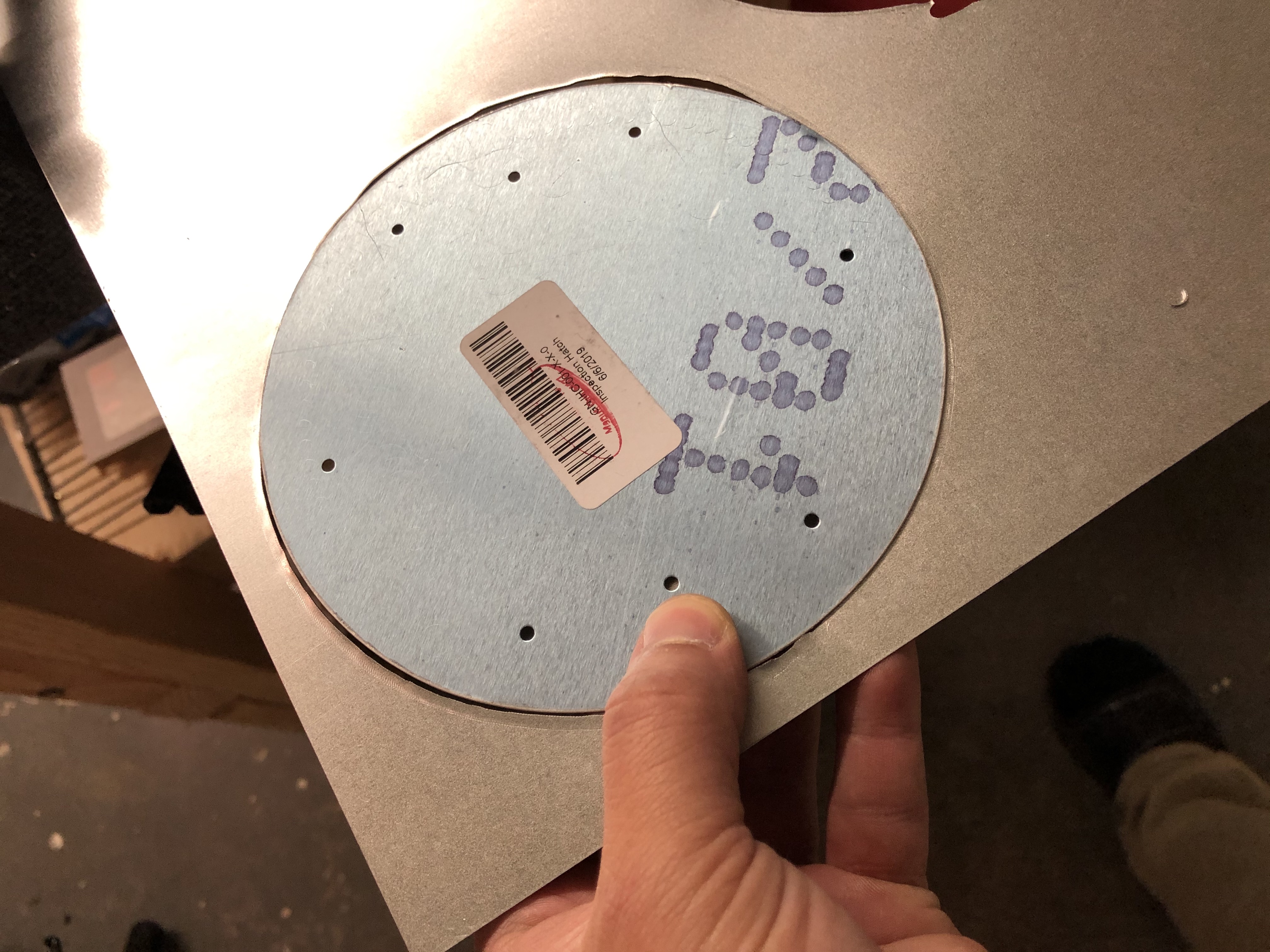
Here are a couple of pictures of the first circle I cut – note that briefly I had the pivot point jump out of the hole, which caused me to waver a bit which you can see towards the bottom where it’s not perfectly round, so make sure the pivot continues to stay in the hole.
Annotated video of the process of cutting the hole
With the ribs for the Flaps out of the way, I am ready to finish the flaps. First order of business is to ensure that I have the ribs all in the right order.
Once that was figured out, I first clecoed the ribs in place to the bottom of the skins and then closed up the skins and clecoed the top as well.
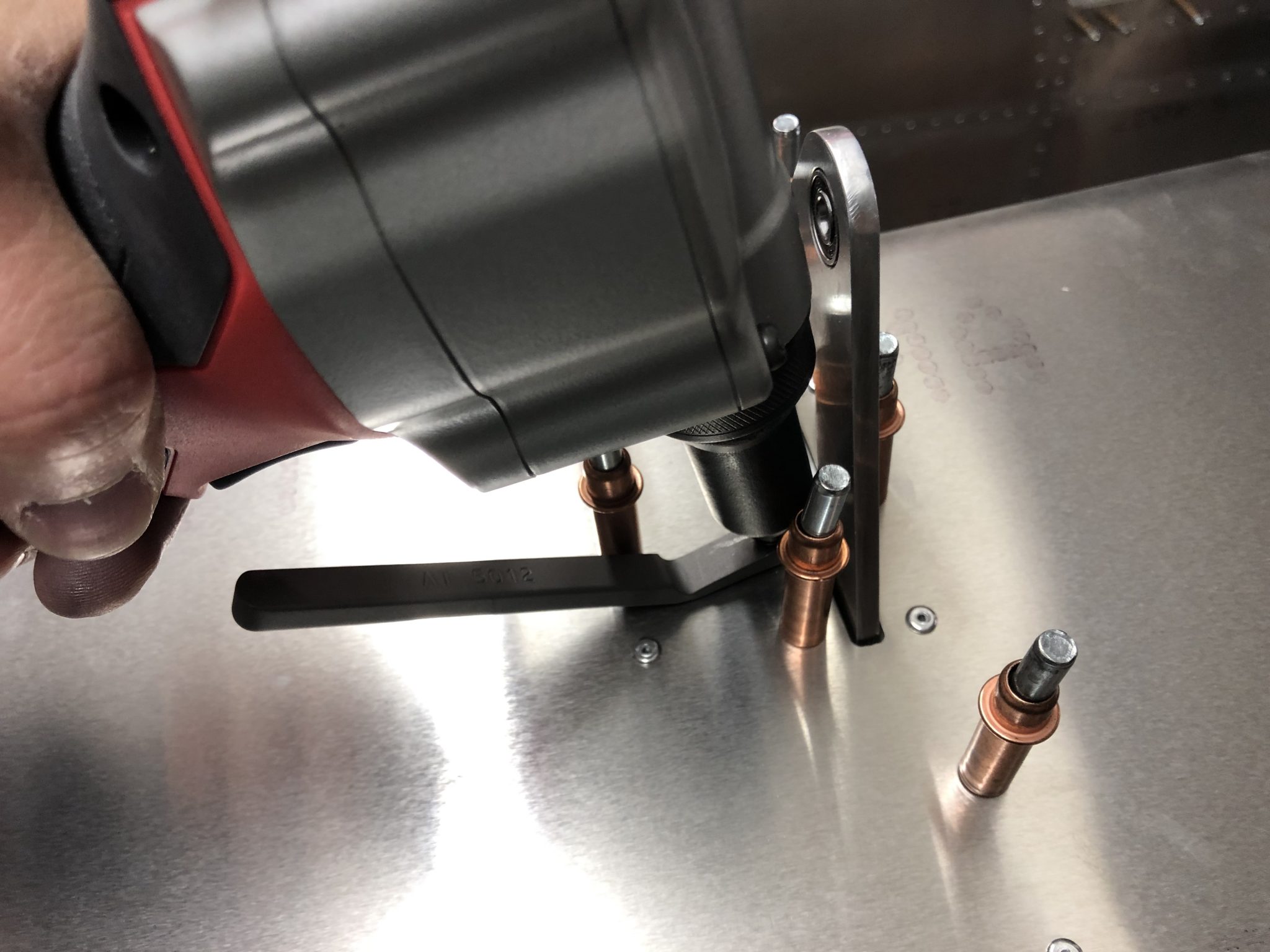
After checking that everything is aligning properly with the skins, I started riveting the skin. The top side is pretty straightforward. For the bottom side, there are a couple of tight spots next to the hinges, so the close quarter rivet wedge came in handy for a couple of the rivets.
With the right side Flap finished and closed up, I then repeated it all for the left side Flap. There was also a couple of the edges where the hinges sit that needed a bit of deburring attention.
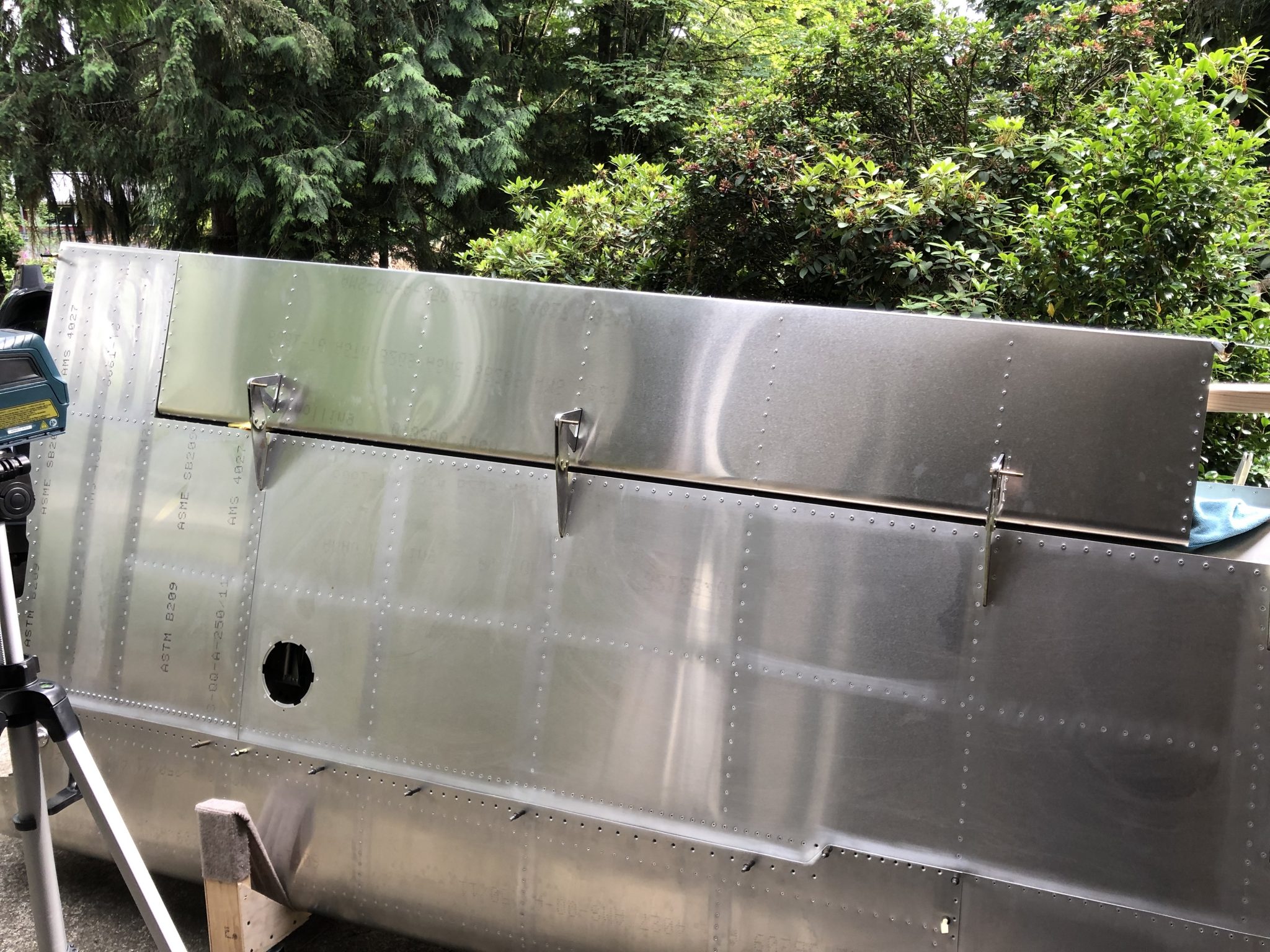
After I finished the top skins, I did one quick alignment test fit on the wings and everything looked good, so then I finished up both sides by riveting the front rivet lane that closes the skin against the other side.
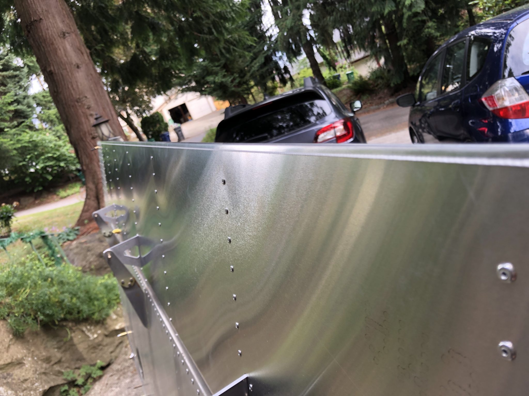
Final alignment check
Once I finished all the riveting, I did one final test fit onto the wings. I used a bit of mason string and my laser level and everything is looking good. Now onto finishing the Elevator.
With the priming of the Flaps ribs out of the way, I got started riveting the Flaps. First order of business was laying out all the ribs in the correct order.
After laying out the ribs in the correct order, I started laying out the right hinges to go with each rib. There is one interesting rib that needs to be riveted in two steps as one part goes on top of the other:
Once I figured all of that out of the right side Flaps, I repeated the steps for the left side Flaps:
I received the missing rivets for the assembly the other day, so now I was able to finish the riveting all of the hinges to the ribs to actually complete the flaps.