Tag Archives: alignment

Completing the rear seat

Hours: 4

After a bit of a hiatus, back to building.

With the help of my other half, we completed the bottom part of the rear seats and put it all together to finish it. This was truly one of those tasks where 4 hands can finish it all in half the time.

Clecoing the ribs
My helper in action

With everything clecoed together and fitted, time for some rivets.

All clecoed in place
Riveted the bottom half

Once that was all riveted together, we combined the bottom and top bench with the hinge.

Clecoing the bottom and top halves together
Riveting the top seat back to the bench from the back.

One piece of note here as the instructions don’t quite call out what orientation the hinge should be put in place. I did a lot of test fitting to get the ideal hinge-fit for this.

Based on my testing, here’s what I did:
I riveted the top bench from the back as seen in the above picture. And the bottom bench from the front to back, in order for the bench to be able to fold forward completely without interference like this:

Riveted the bottom of the bench from front to back in order for the seat back to be able to fold down without interfering with rivets.

And here’s the happy completed picture:

Completed rear passenger bench

Assembling the rear seat

Hours: 2

With the front seats almost complete apart from the lock pin mechanism, time to assemble the rear seat.

First order of business was to remove the protective plastic and do some inspecting and deburring of the edges and holes.

Laying out the ribs
Ribs deburred

With that out of the way, time to assemble the main rib structure.

Lining up the rib structure of the seats
Backside of the seats with ribs clecoed

On the bottom rib there was a minor misalignment of the rib. The rib extended a little bit beyond the skin, but the holes were all drilled fine.

bottom rib extended a bit too far

So I trimmed off the small part that extended too far.

Sanded it down to finish up with the skin

And on to more ribs to make it a really solid seat.

Complete rib structure clecoed to the back

The last part was to put on the front skin and make sure everything lines up. When I first clecoed it on some of the ribs didn’t align, so I unclecoed the skin again, then centered it and clecoed it again and everything fit well.

Both sides of the skin clecoed in place

Next step will be to rivet it all together.

Building the Left Aileron

Hours: 1.75

With the right Aileron completed, time to build the left Aileron.

Since I figured out the order of assembly last time with the right Aileron, the completion of the left one was very straightforward.

I set in the ribs, then added the balance tube and then went to work clecoing everything together.

Ribs clecoed to the bottom and balance tube inserted in the front.
Top side clecoed and ready to rivet.

And from there it was just riveting everything together.

Bottom done, top ready to rivet

Another quick alignment check before riveting the front line and then I riveted the front line and completed the left Aileron.

Both Ailerons completed

Timelapse of building the Ailerons

Finishing the Right Aileron

Hours: 2.5

With the ribs for the ailerons prepared, time for me to complete and rivet the ribs and the skins to make a complete Aileron.

The instruction manual on the Aileron is still a bit light, so I first had to figure out the order of things. After first doing it wrong and placing the balance tube in first, I realized that this doesn’t allow to place the ribs. So back out with tube, and in with the ribs first.

Lining up the ribs inside the aileron

After I aligned all the ribs I inserted the balance tube and lined it up with the rivet holes. Then I clecoed both sides to start riveting the top and bottom of the skins.

Clecoing the right Aileron
Starting to rivet the top

After I was done with riveting the top and bottom of the skins, I took off the clecos from the front and did a test fit on the wings to check the alignment.

Checking alignment using a mason line

Everything looks good, so I clecoed the front line again and started riveting to finish the Aileron.

Riveting the balance tube
Clecoed the front line after checking the alignment

And here’s the completed right Aileron:

Completed right Aileron

Riveting the Elevator skins

Hours: 3.5

With the final preparations and alignments of the Elevator done, the last task is to rivet up the Elevator skins.

Horizontal Stabilizer and Elevator temporary joined for alignment and looking good

The process is pretty straightforward, but there are a lot of rivets to be pulled, so it’s a lot of repetition, so I spread the work out over a few sessions.
Setting up rivets Almost done with the left underside Finished left underside

I first did the half of the bottom, both left and right side, and then finished up the left side completely, followed by the right side.
Setting up the final few rivets for the right underside Bottom of the entire Elevator completed

For the Trim Tab control tabs I had to get out the close quarter wedge.
Using the close quarter wedge to be able to attach the rivets for the Trim tab Control

After I finished the entire bottom half of the Elevator I flipped it around and put a small padding onto the Trim Tab control so it can’t dig into the Elevator skin.
Protection for the Trim Tab control

Final Elevator fitting

Hours: 2.5

After reinforcing parts of the fiberglass tips for the Elevator for the front section that is countersunk to support the flush rivets, I finished fitting of the right side of the Elevator.

When I finished the alignment of the left side of the Elevator, I ran out of clecos, so I bought a couple more when I was at Oshkosh so I could properly put the Elevator together and get everything to align correctly.

So the first order of business was to finish clecoing everything including the (correct) control tabs for the Trim Tab.
Time to cleco the right side of the Elevator Everything clecoed together including the Trim Tab

With that out of the way, I moved on to do the fitting for the right side fiberglass piece. It took a little bit of aligning and filing away a tiny bit from the back so that the fiberglass piece can slot into the metal.

Once that looked all good, I started to do the match drilling of the holed into the fiberglass.

Time to drill some holes into the fiberglass tip First hole drilled and clecoed Continuing the match drilling All holes drilled

Now the only last part to do was to countersink the front parts of the fiberglass tips in order to allow the flush rivets to sit in there. It took a bit of back and forth to calibrate my microstop countersink attachments to ensure I had a good flush fitting.

Marked out for the holes that need to be countersunk Finished countersinking the holes Flush fit of the left side Alignment checks on the right side

Elevator Trim tab & left fiberglass tip fitting

Hours: 4

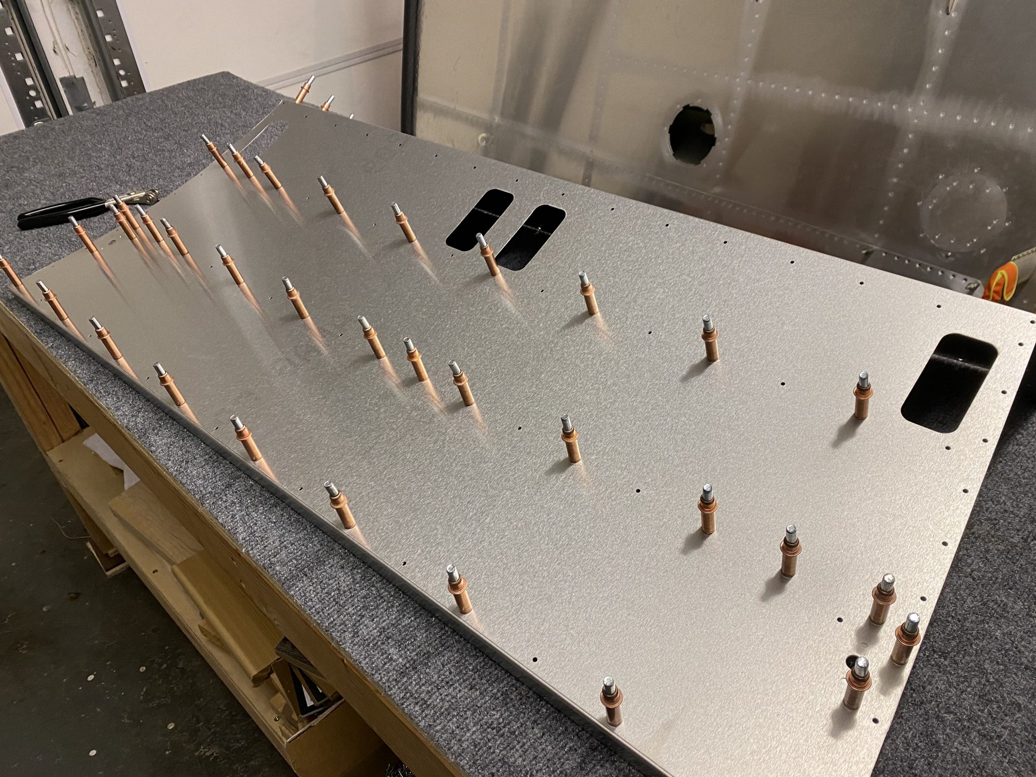
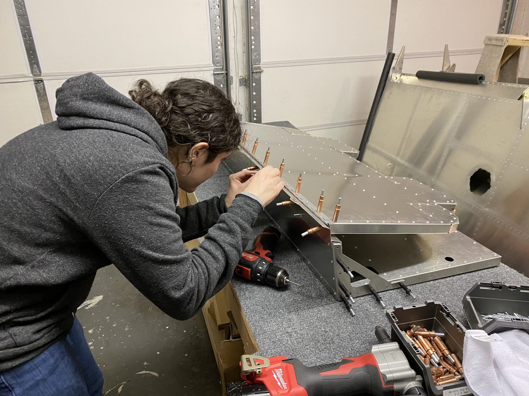
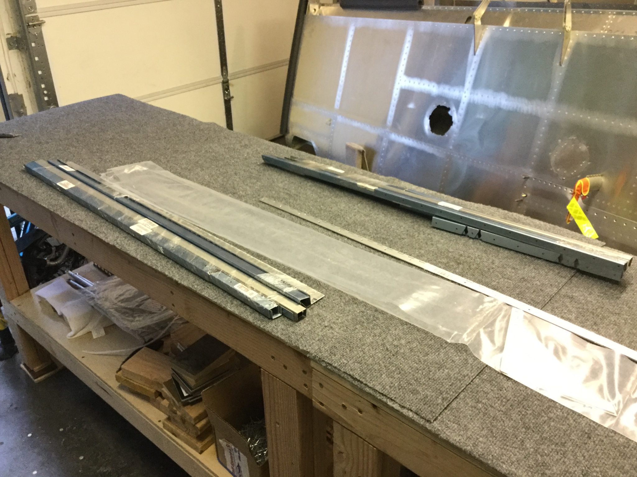
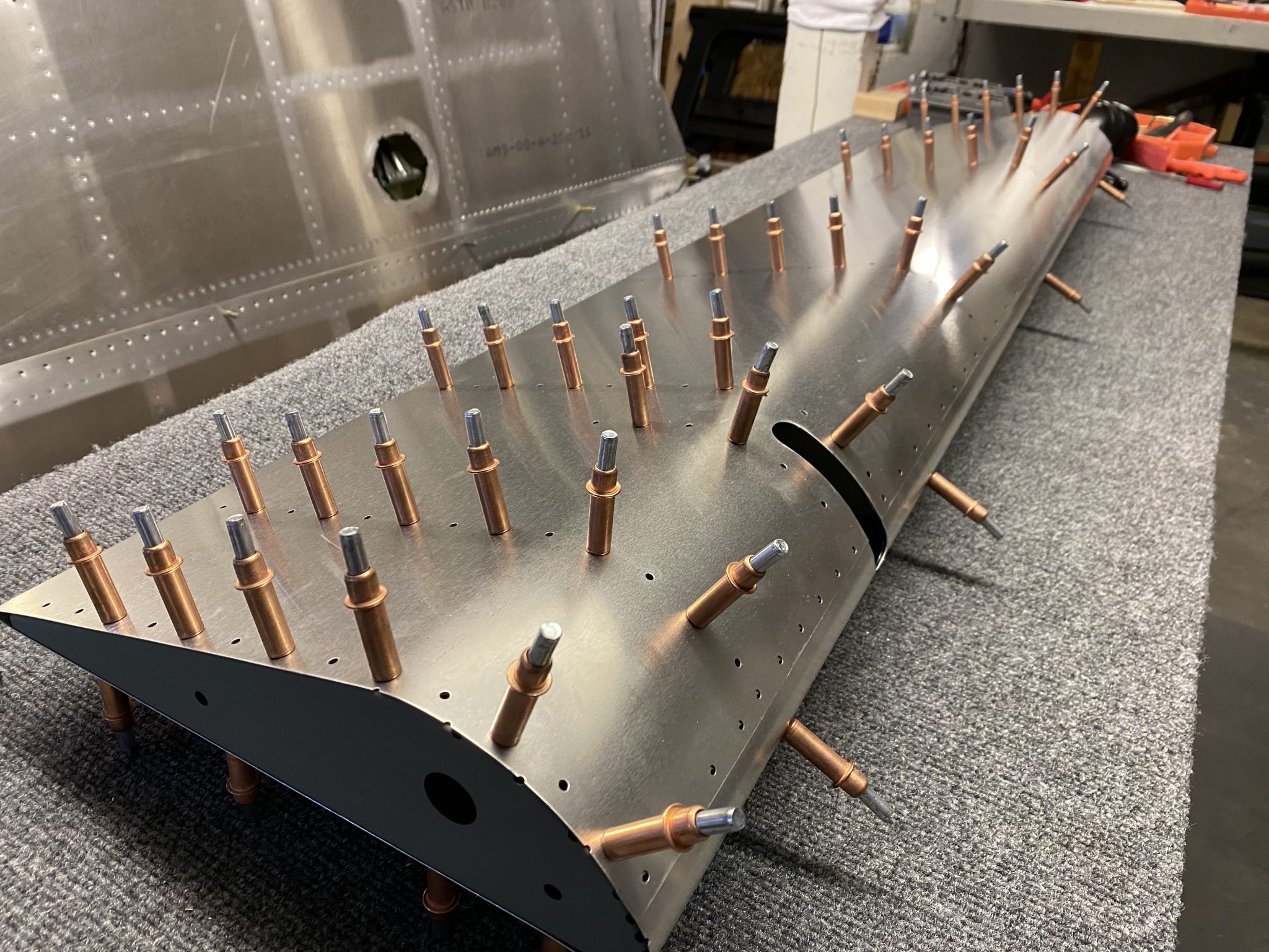
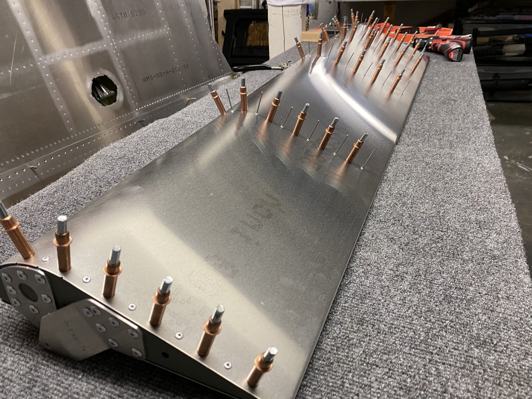
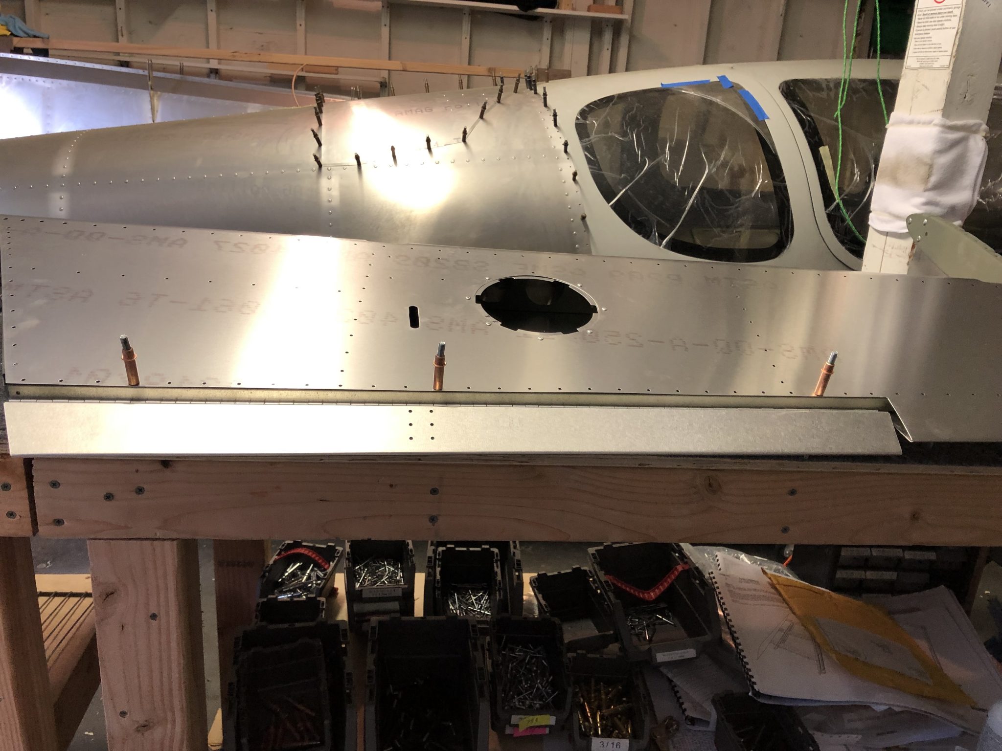
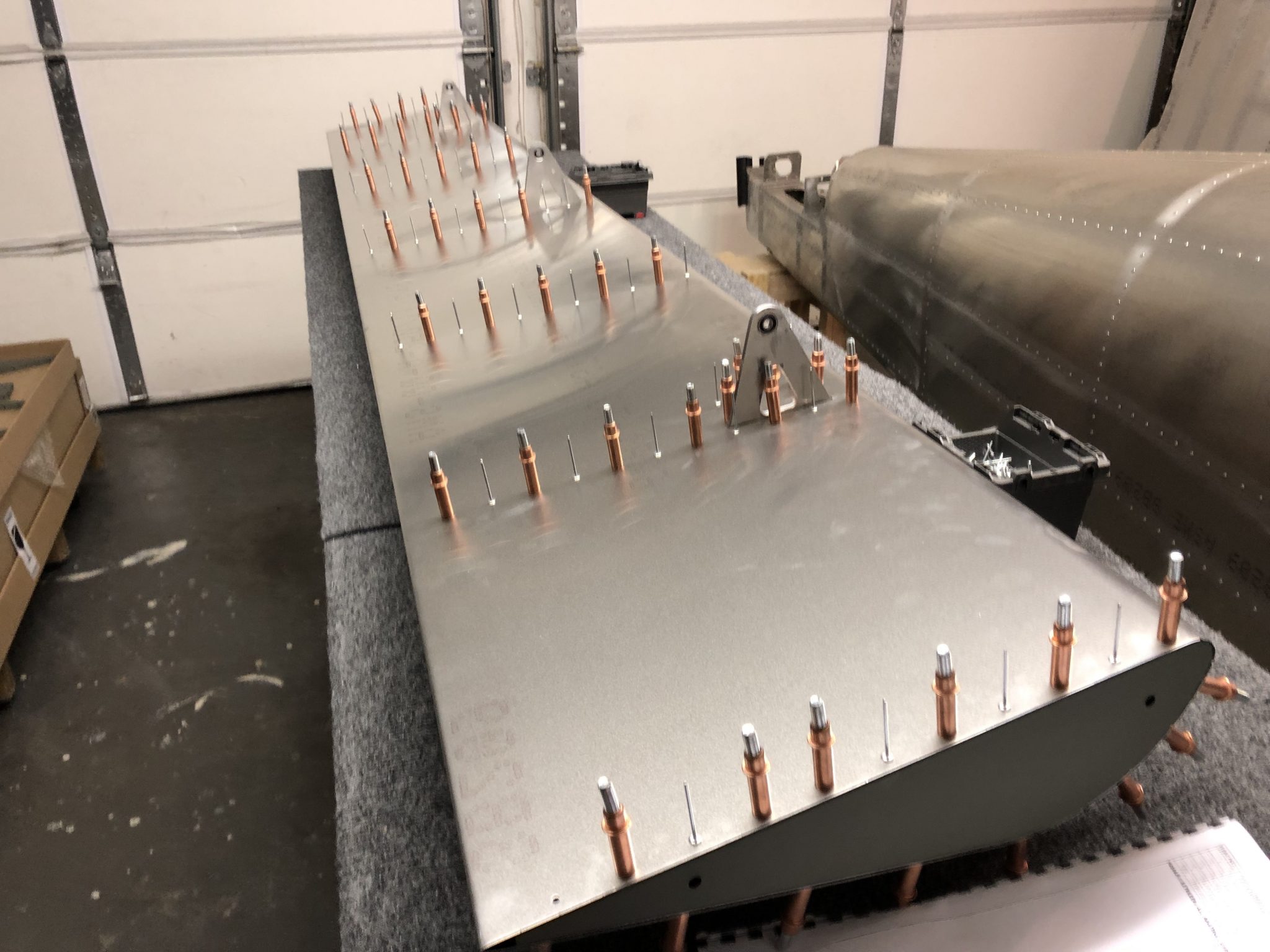
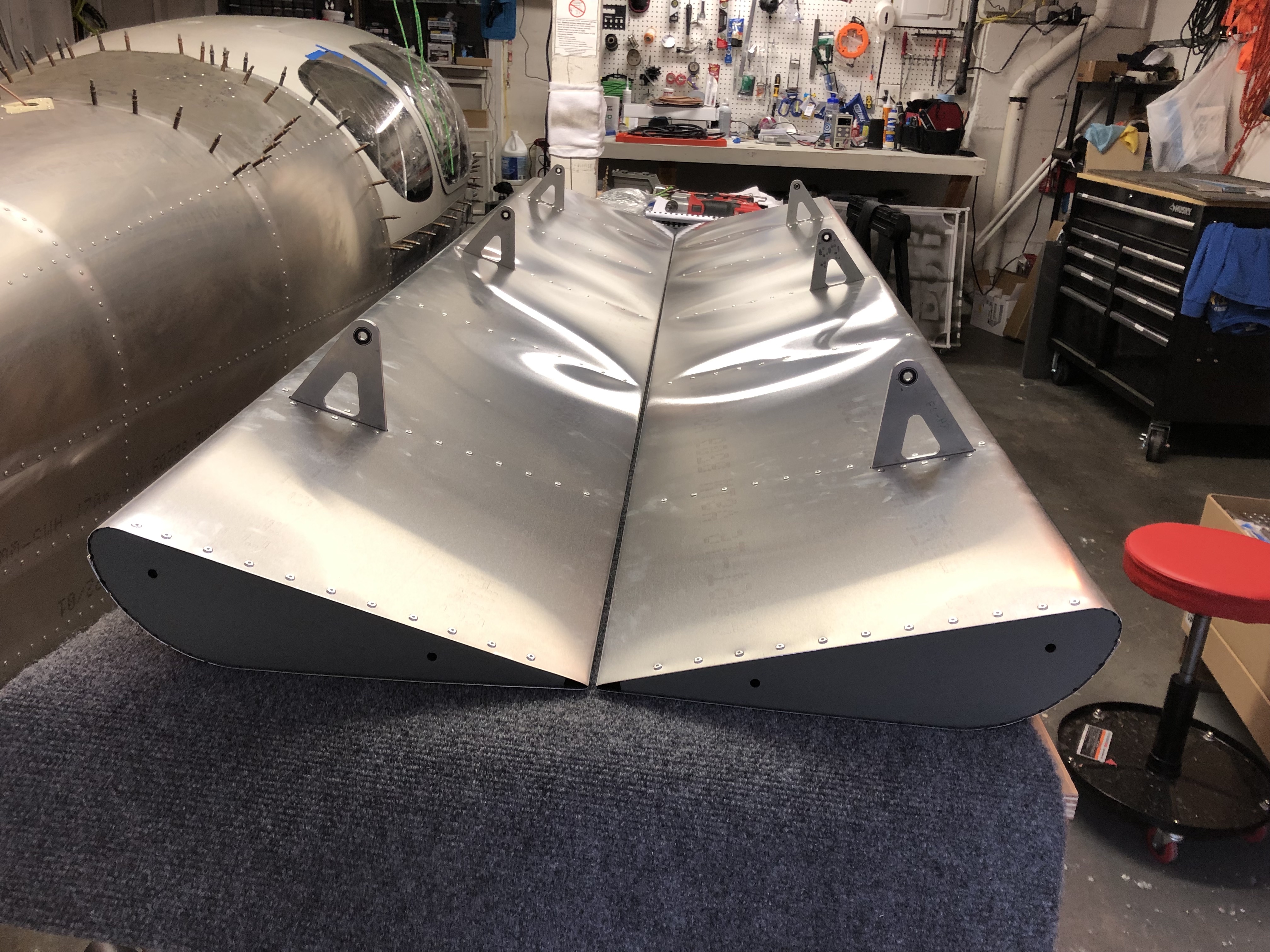
With the two main skins fitted onto the Elevator, I started looking at the trim tab and the side fiberglass tips.

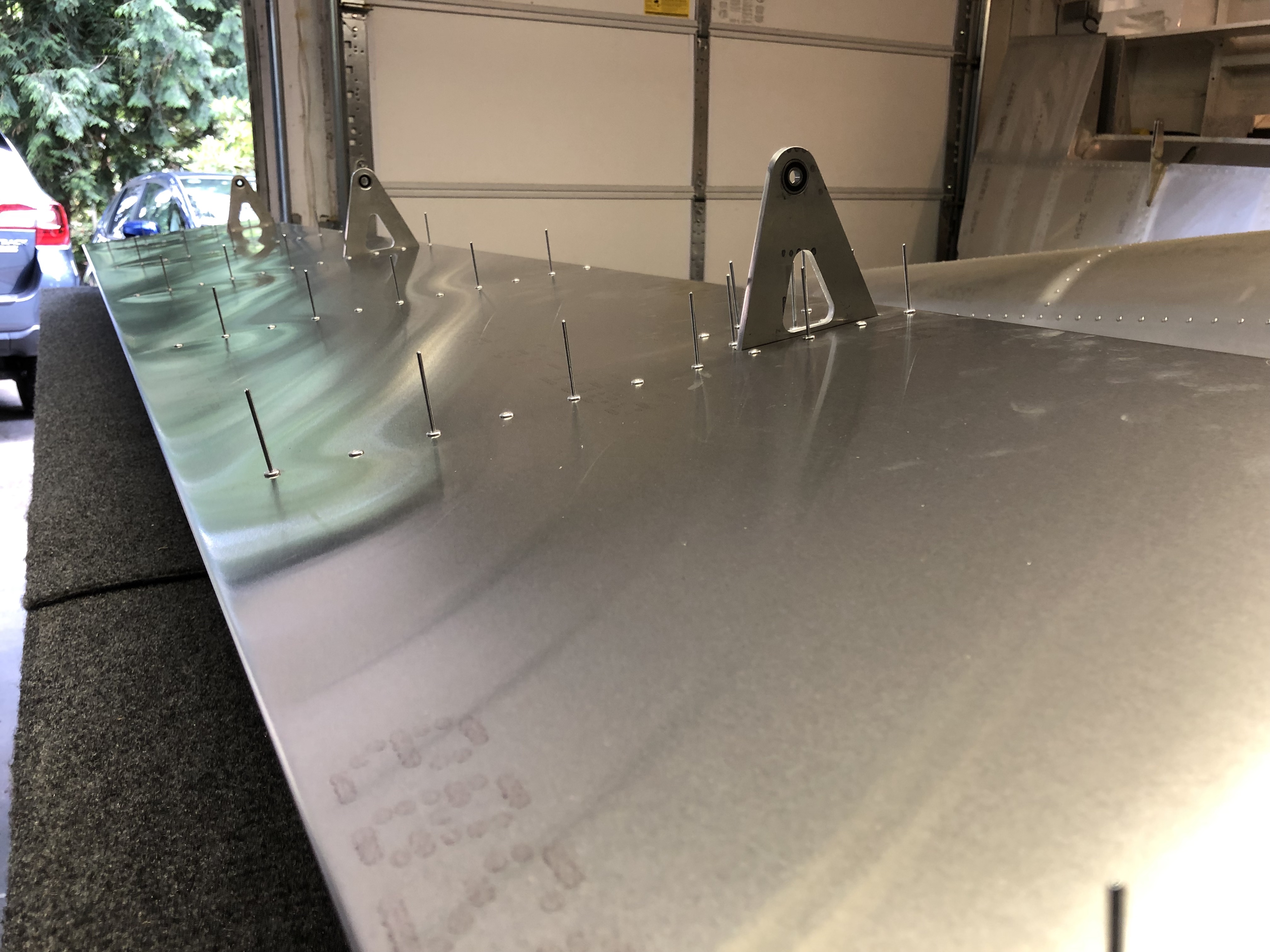
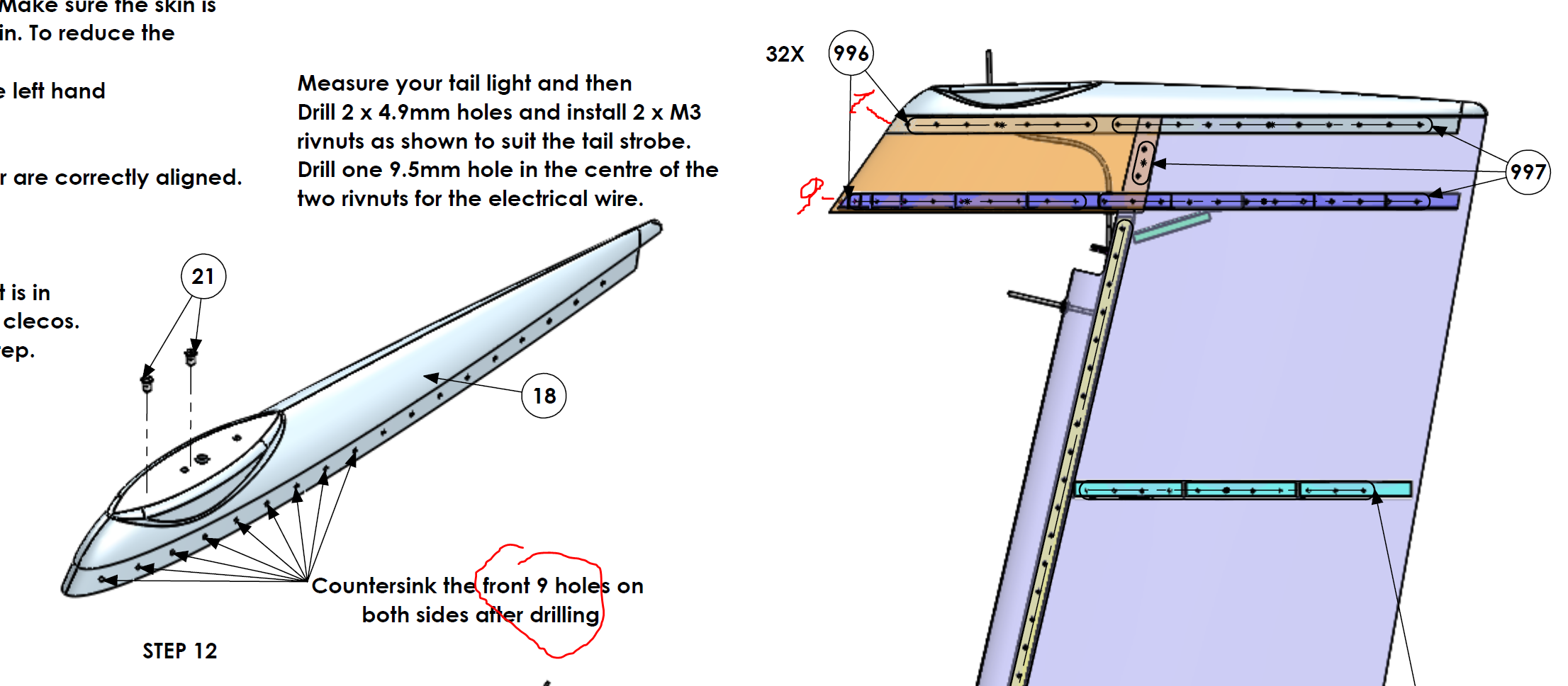
First I figured out the correct orientation of the hinge that connects the Elevator and the trim tab and the right orientation of the trim tab. I temporarily clecoed them together to check that the clearances are good and it moves all fine.
Elevator trim tab temporarily mounted

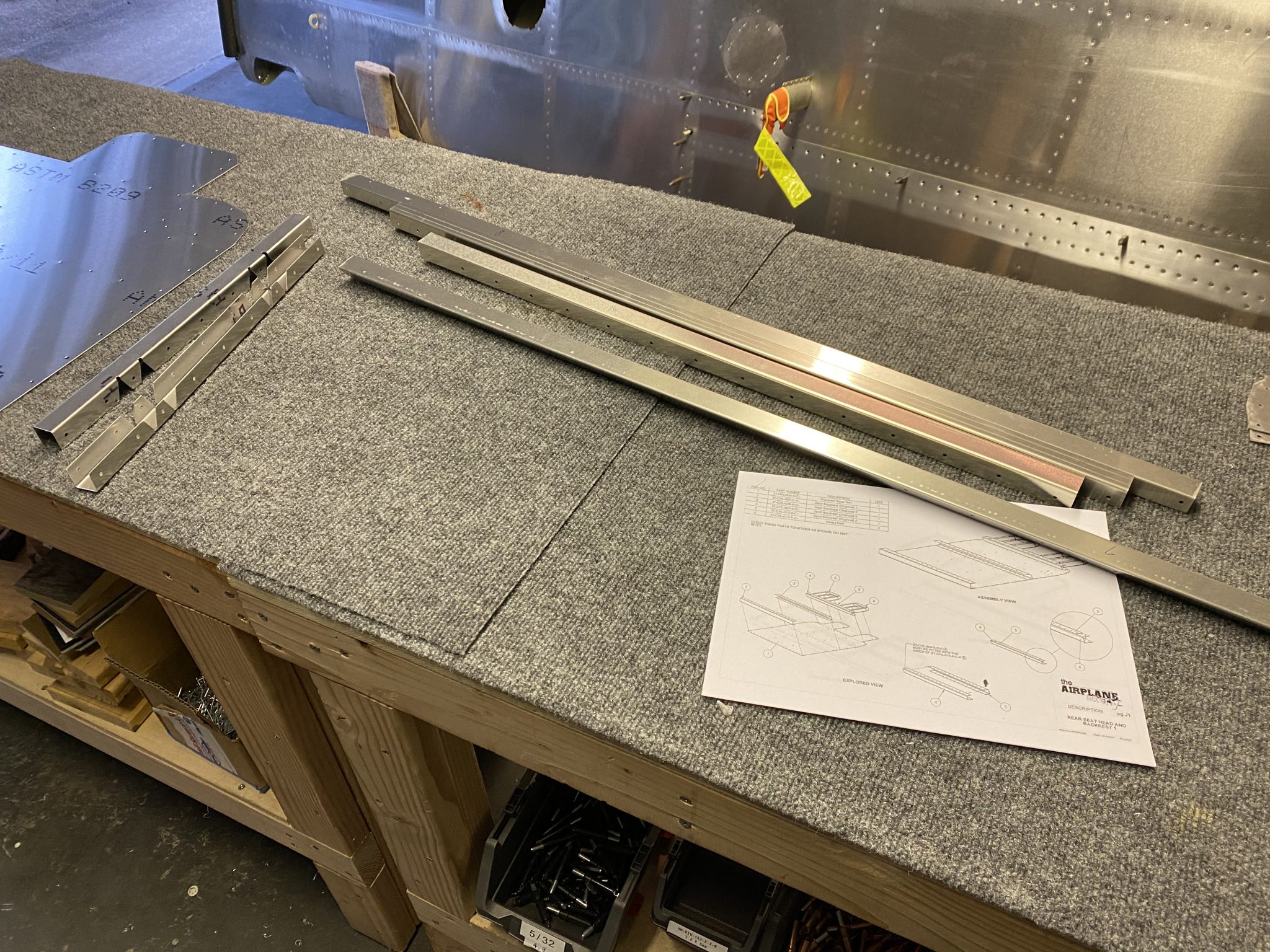
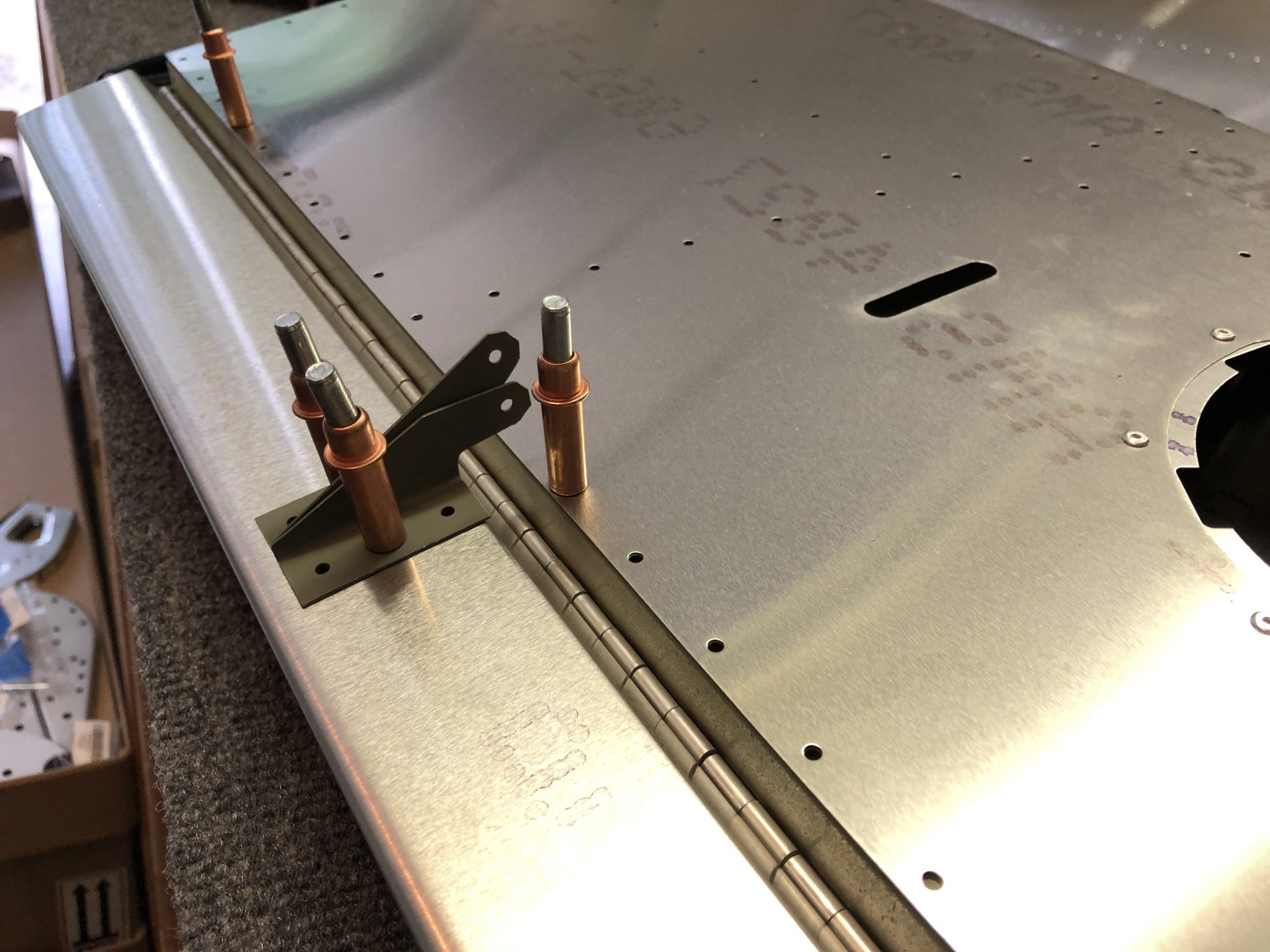
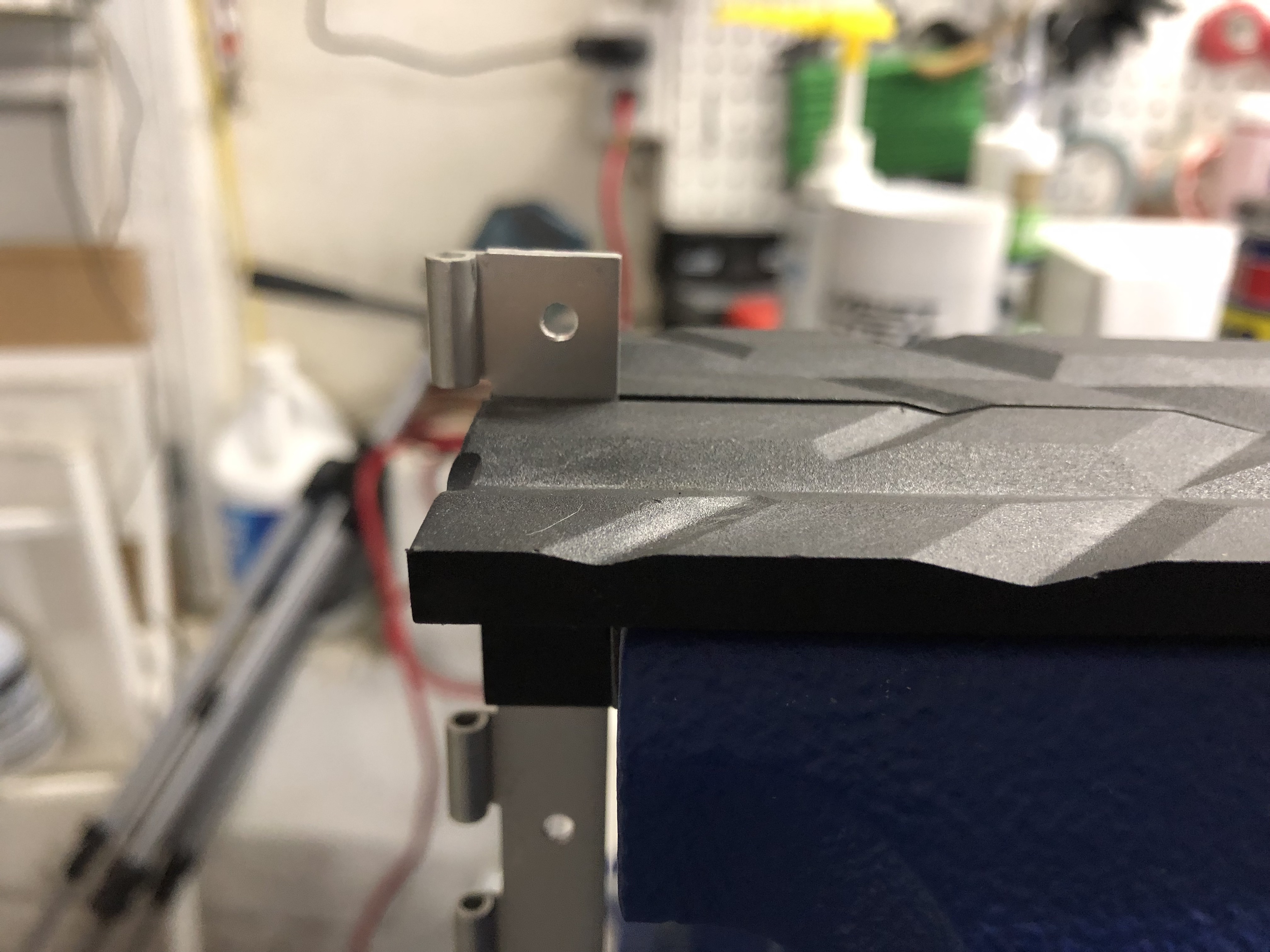
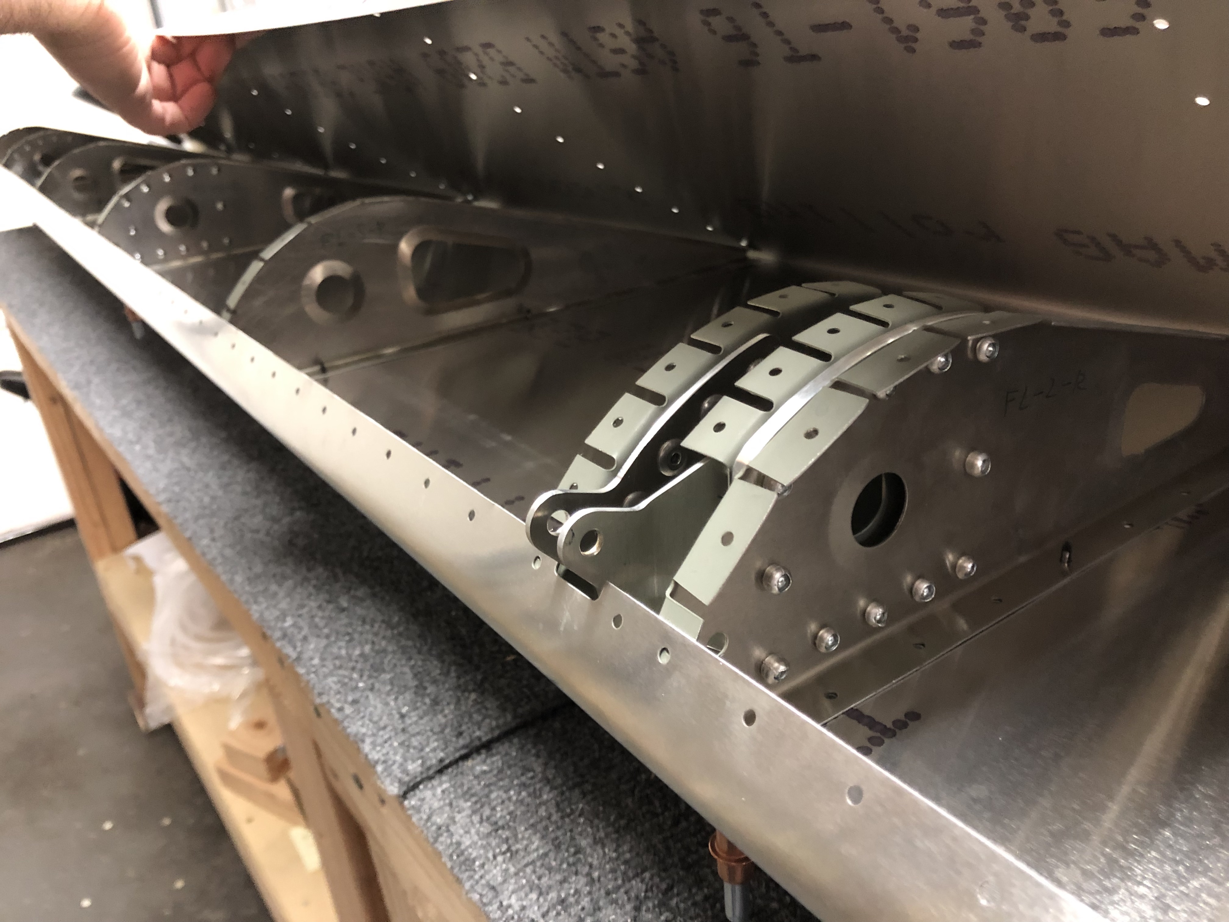
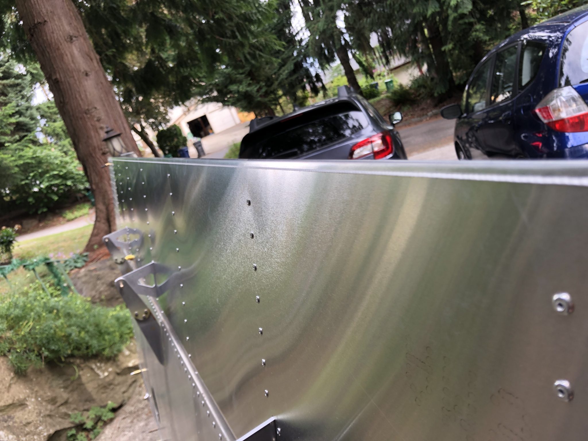
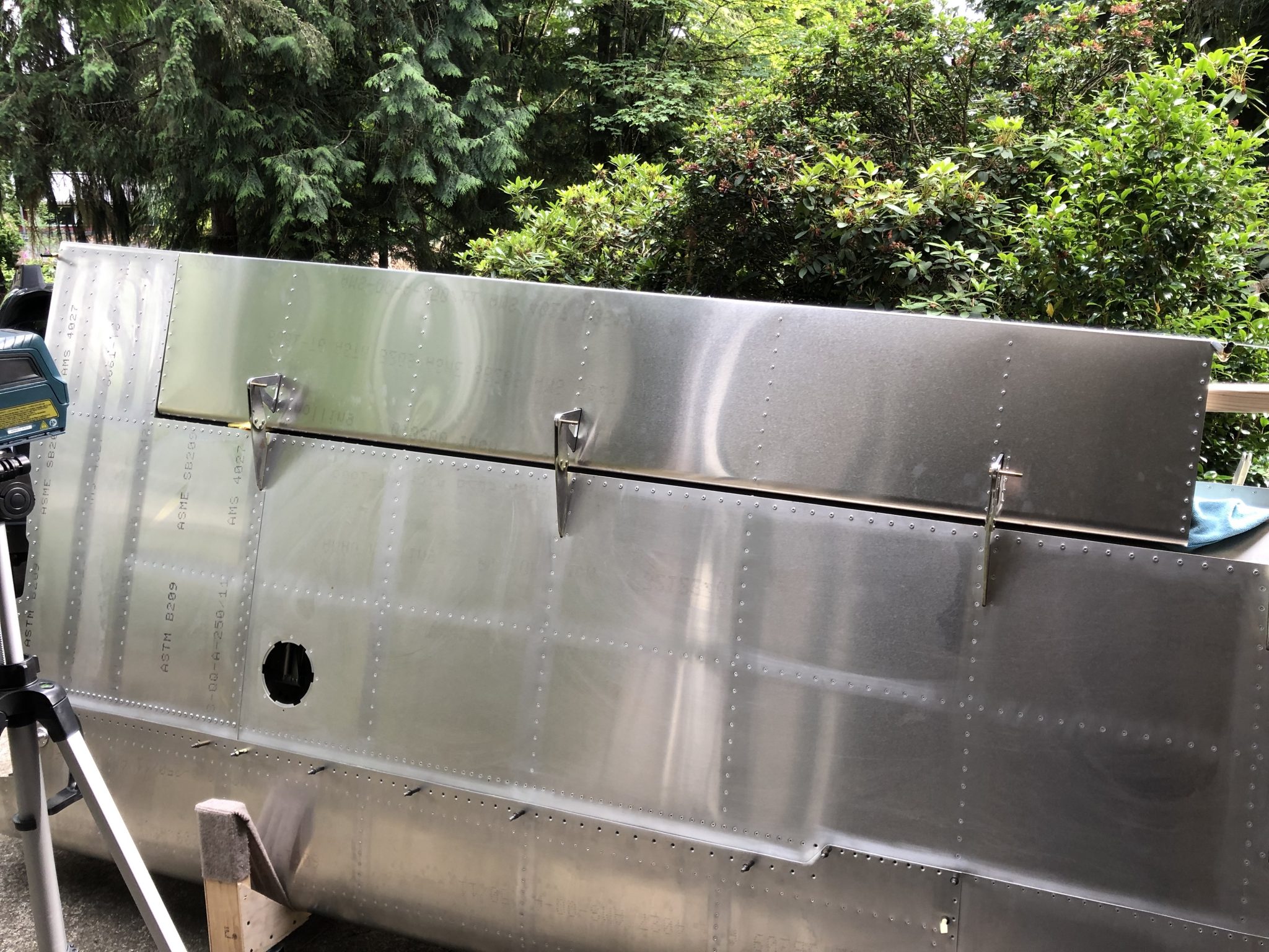
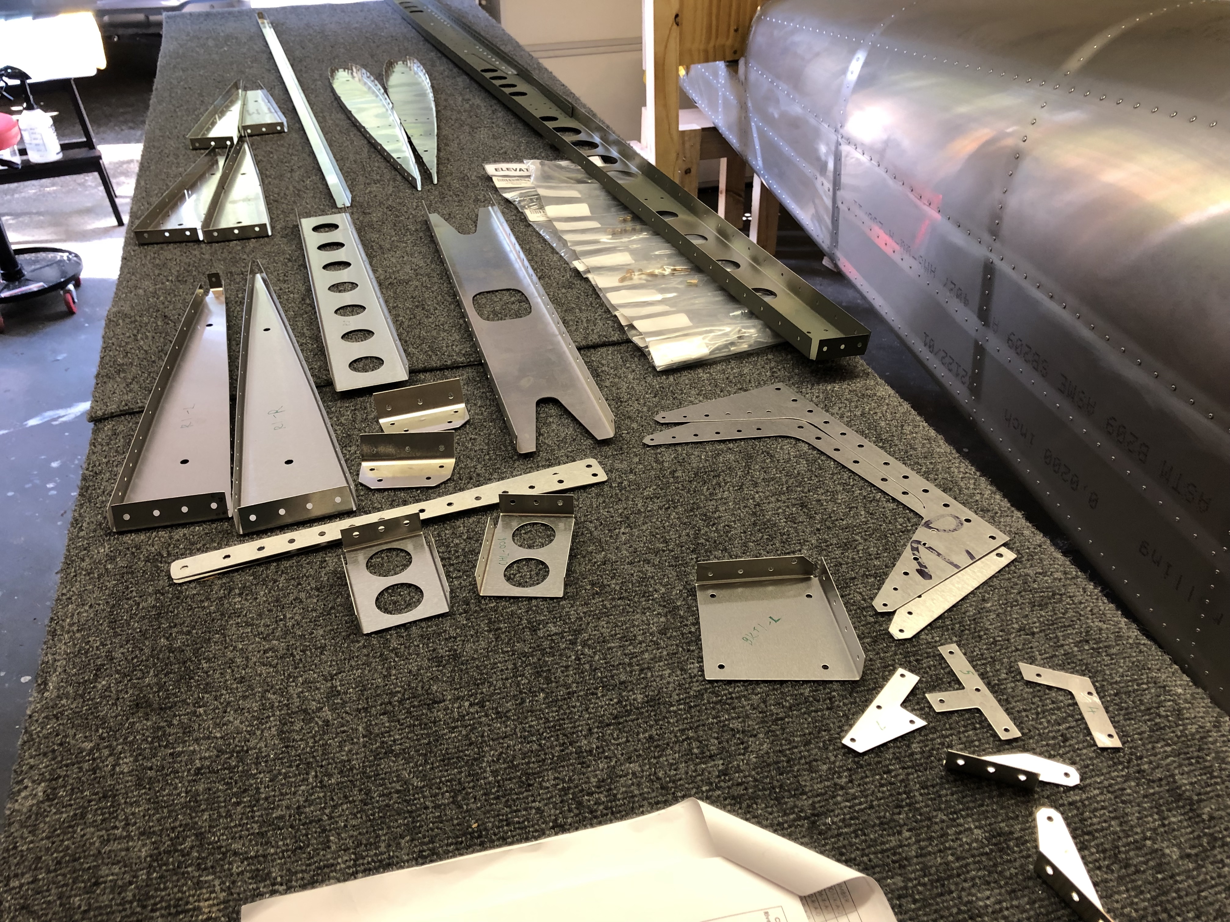
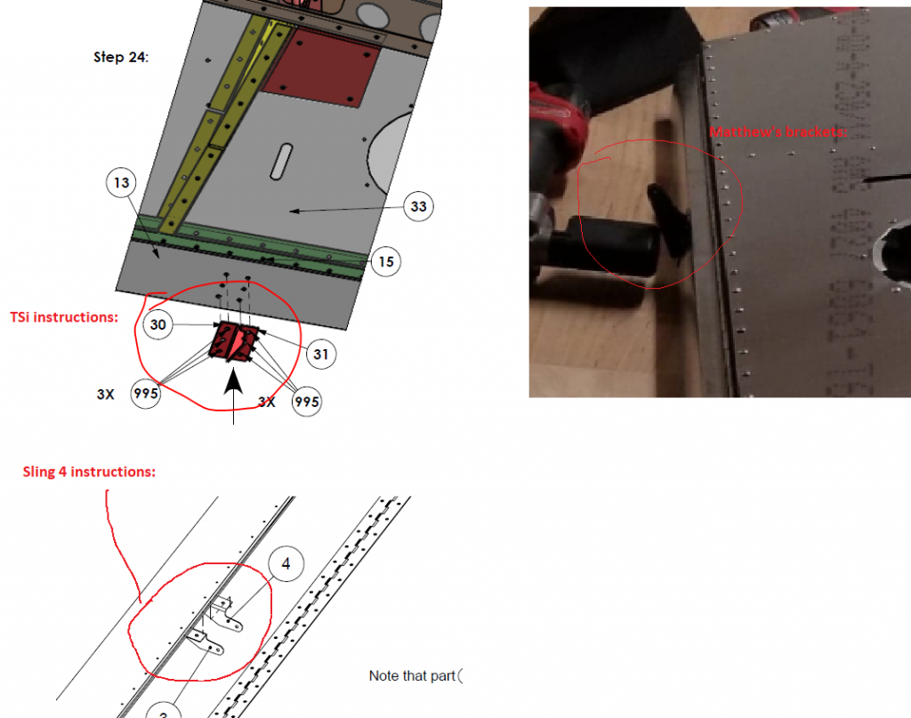
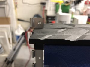
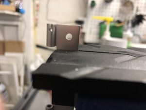
Then I was searching for the brackets that go on top of the trim tab and realized that I got two different looking brackets. Since this looked off to me, I tried to squint real hard at the instruction manual to figure out which bracket is the right one. I also checked the Sling 4 instructions and asked Matthew if he had a picture of his brackets and with that figured out that I must have received one TSi and one Sling 4 bracket, so I put in a note with the factory so I can get the right bracket for my TSi.
This looked off to me - I figured out it's one TSi and one Sling 4 Trim tab bracket
Investigative work to figure out which bracket belongs

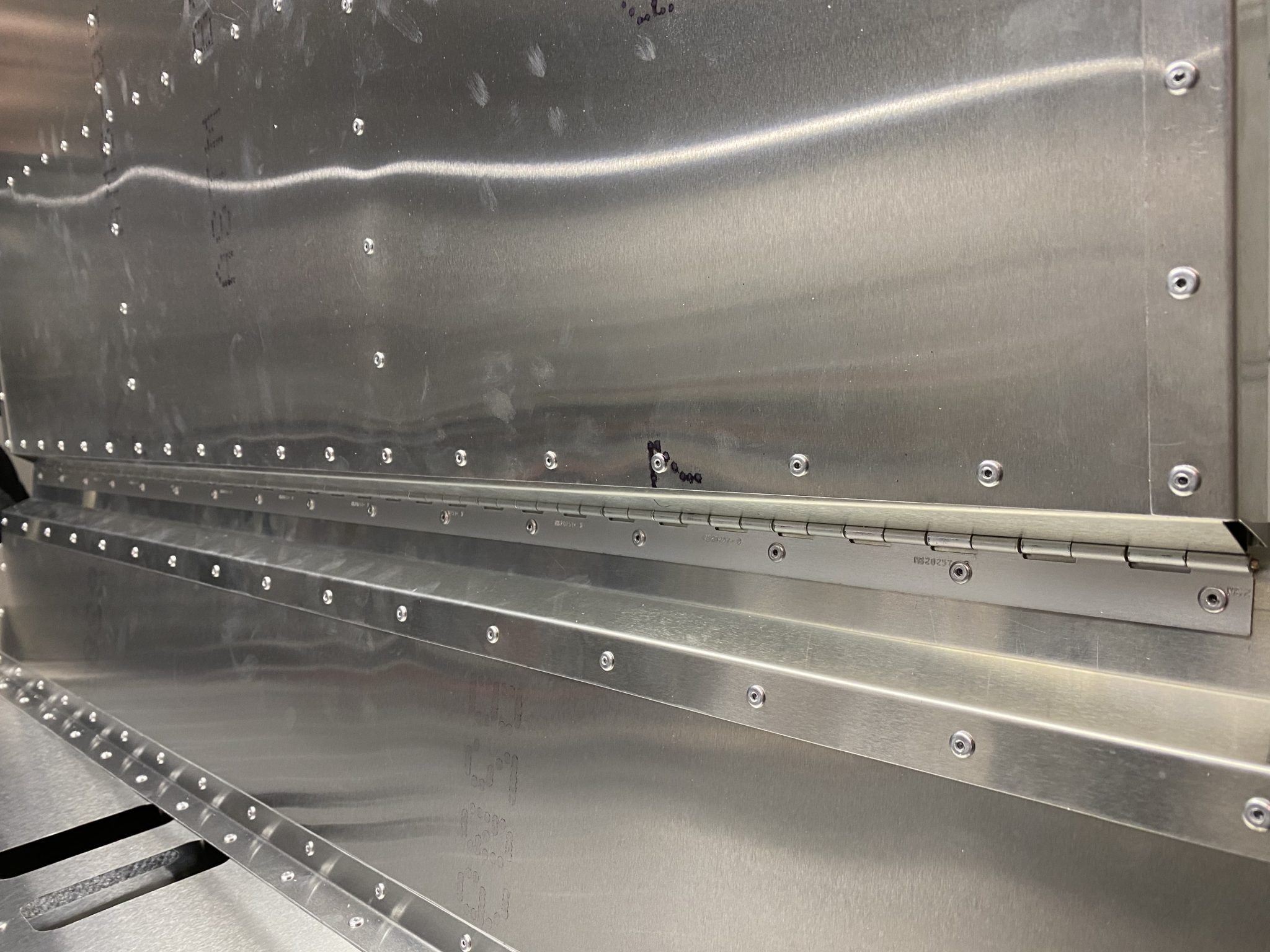
Securing the trim tab piano hinge

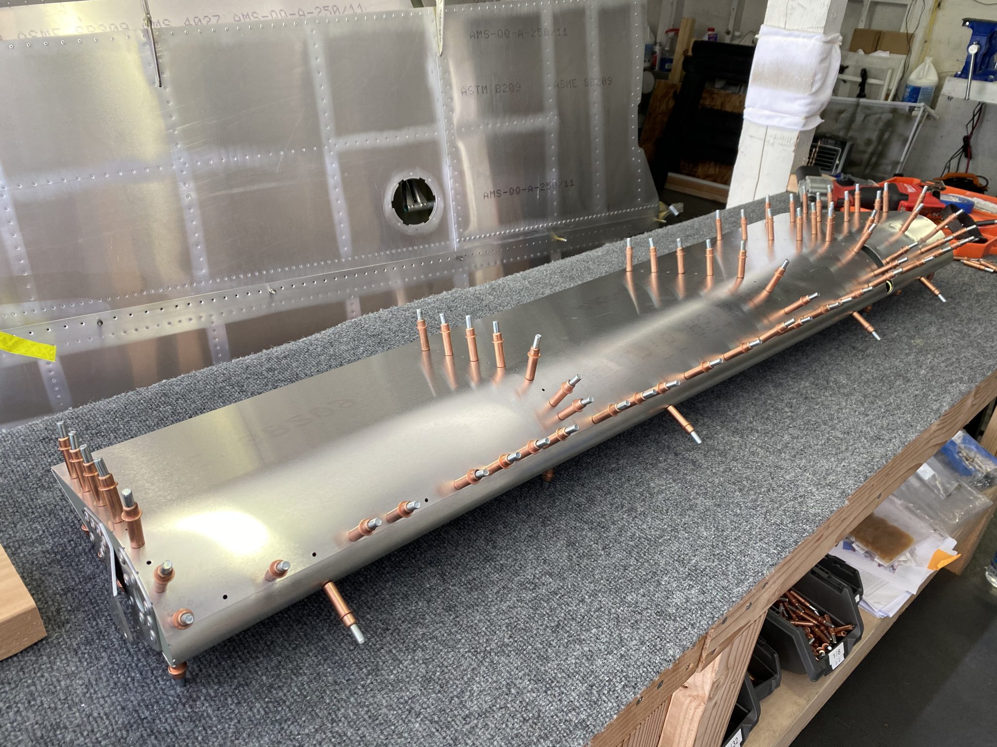
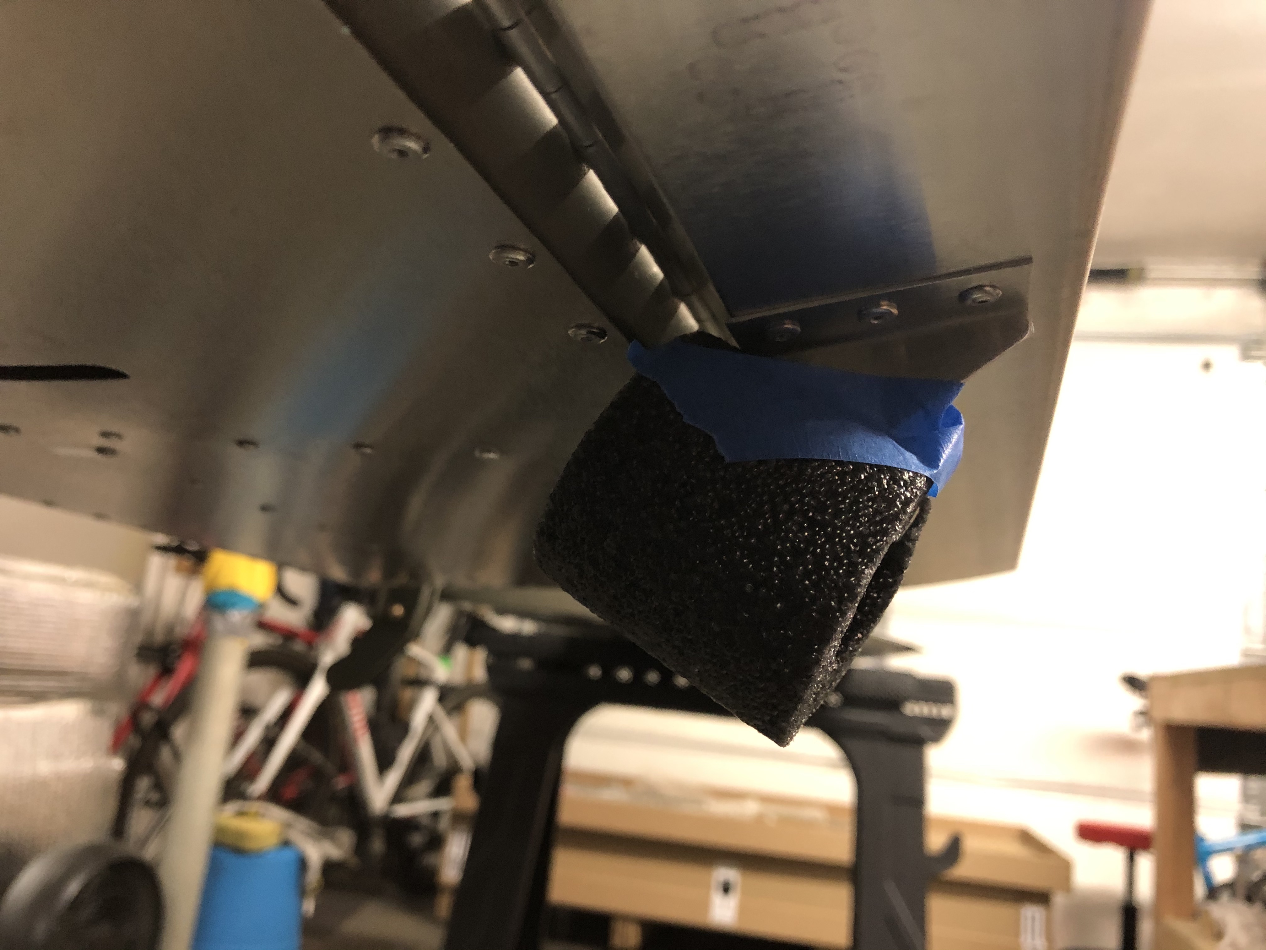
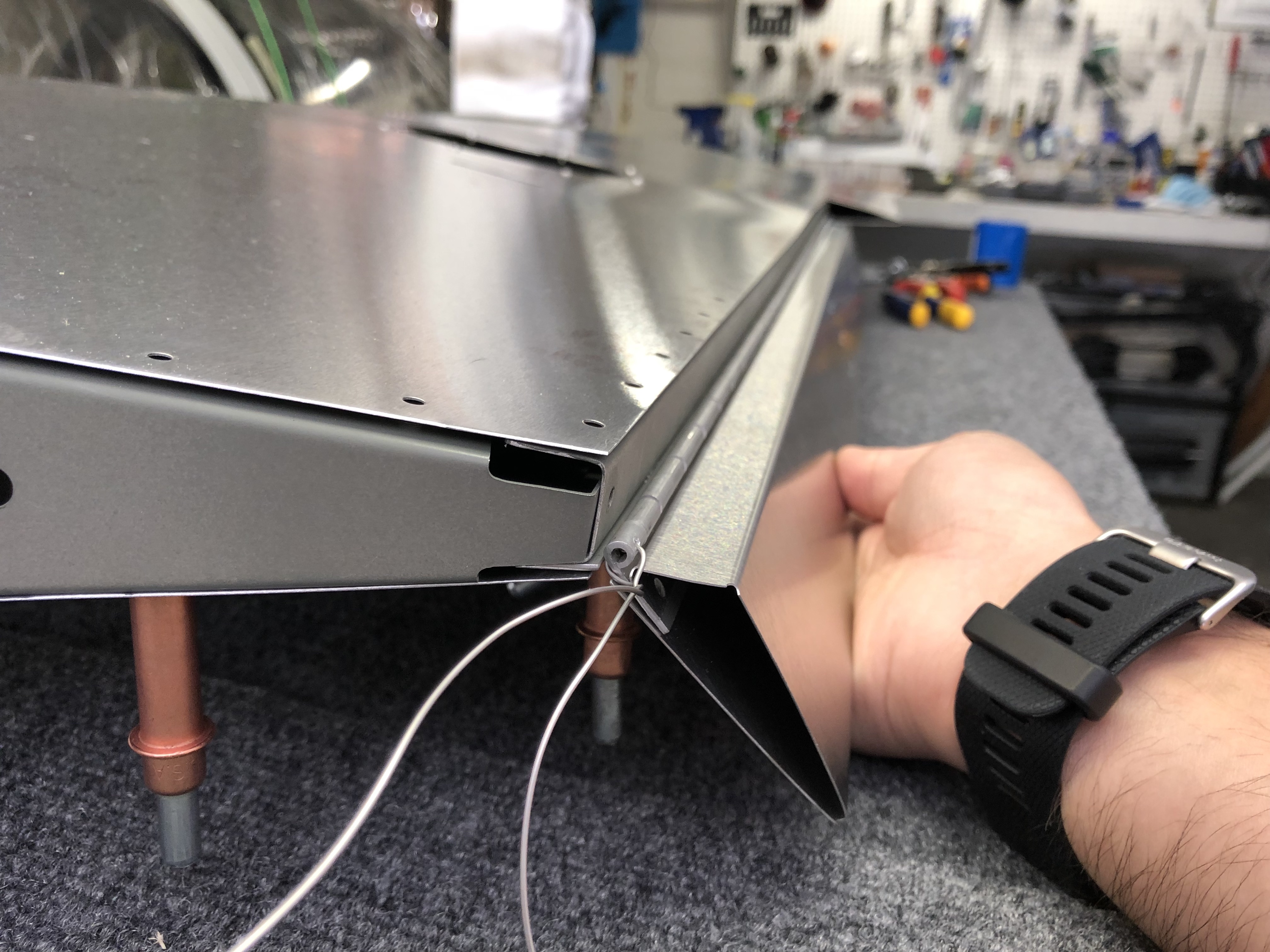
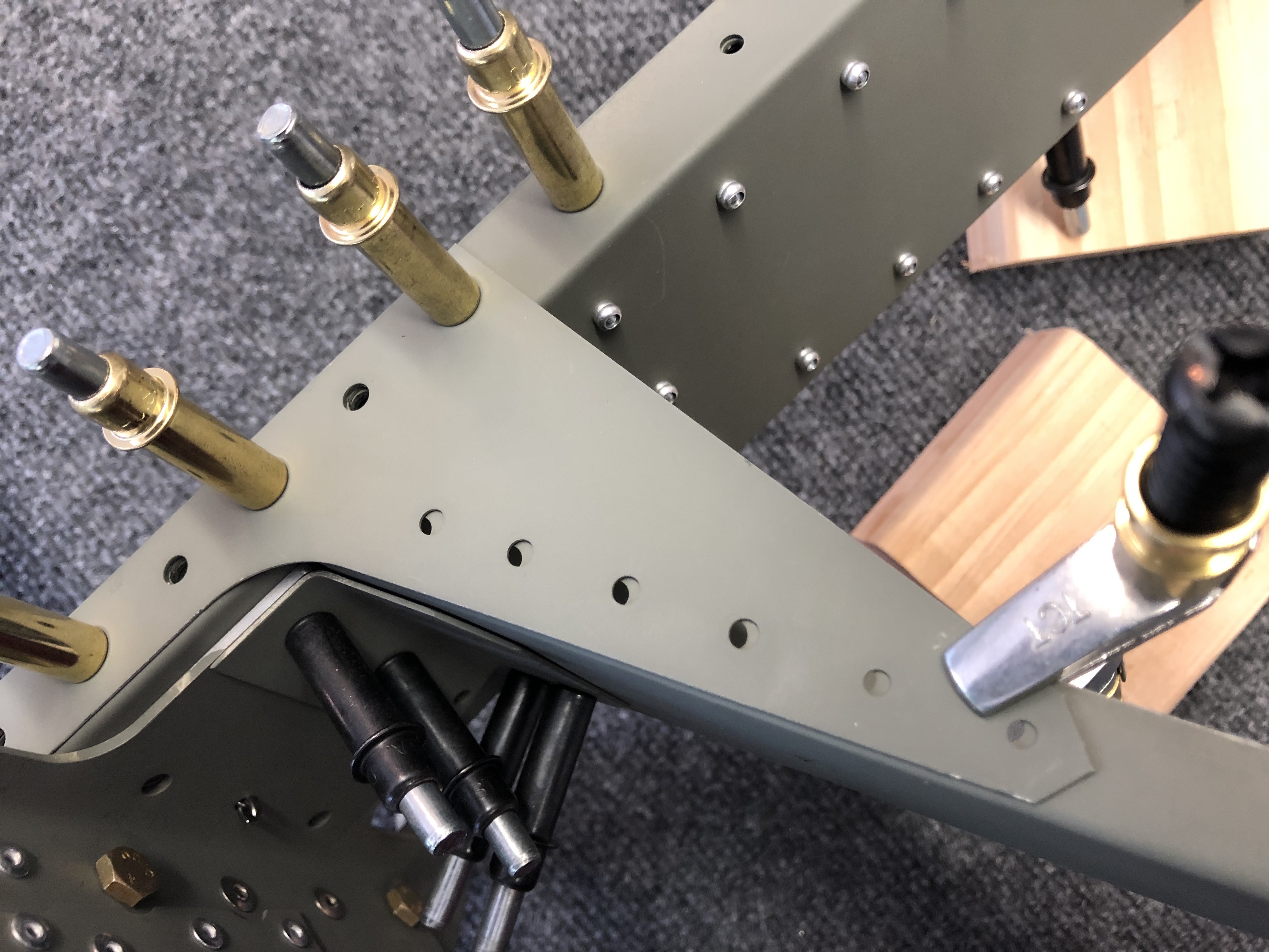
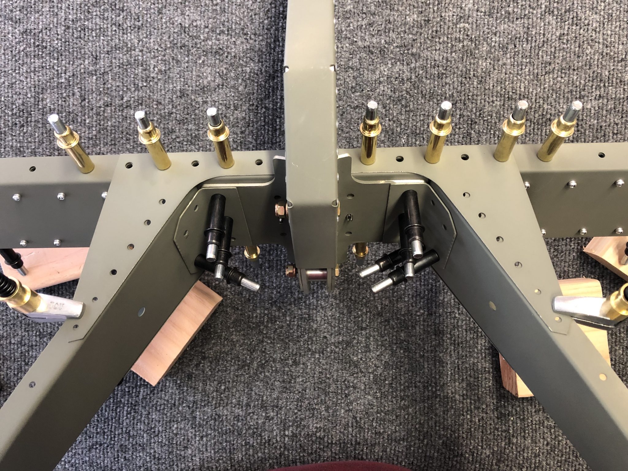
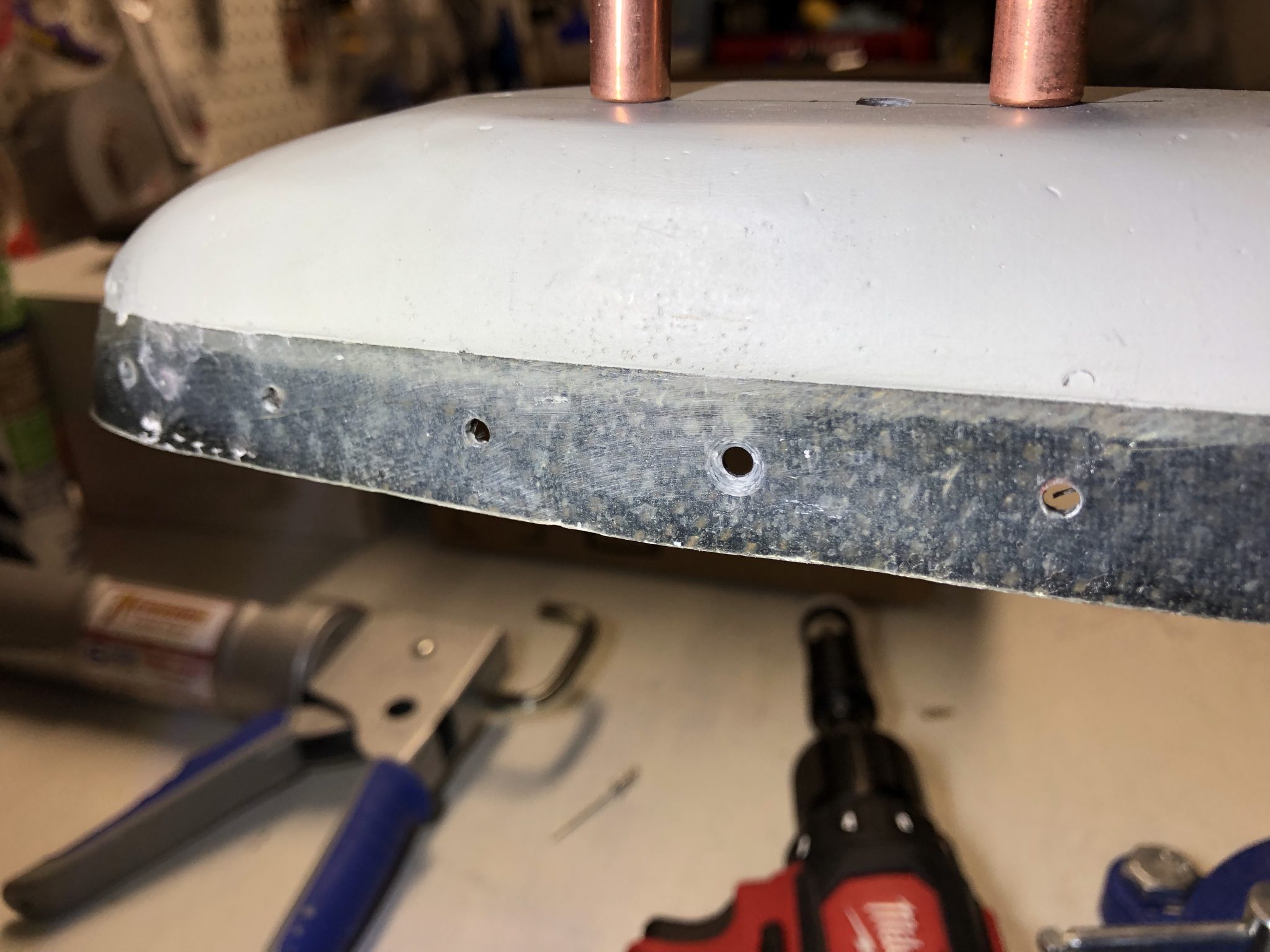
With that out of the way, I focused on thinking about securing the piano hinge that attaches the trim tab to the elevator. Since there is no natural stop for the pin that goes through the hinge on either side, it could happen that it becomes lose from vibration and thus could come out during flight, which would be bad. I research a bit on the topic and found this article from EAA on the use and installation of piano hinges.

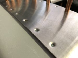
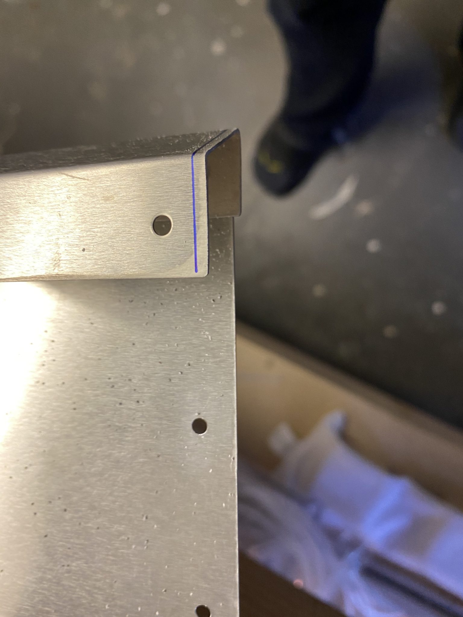
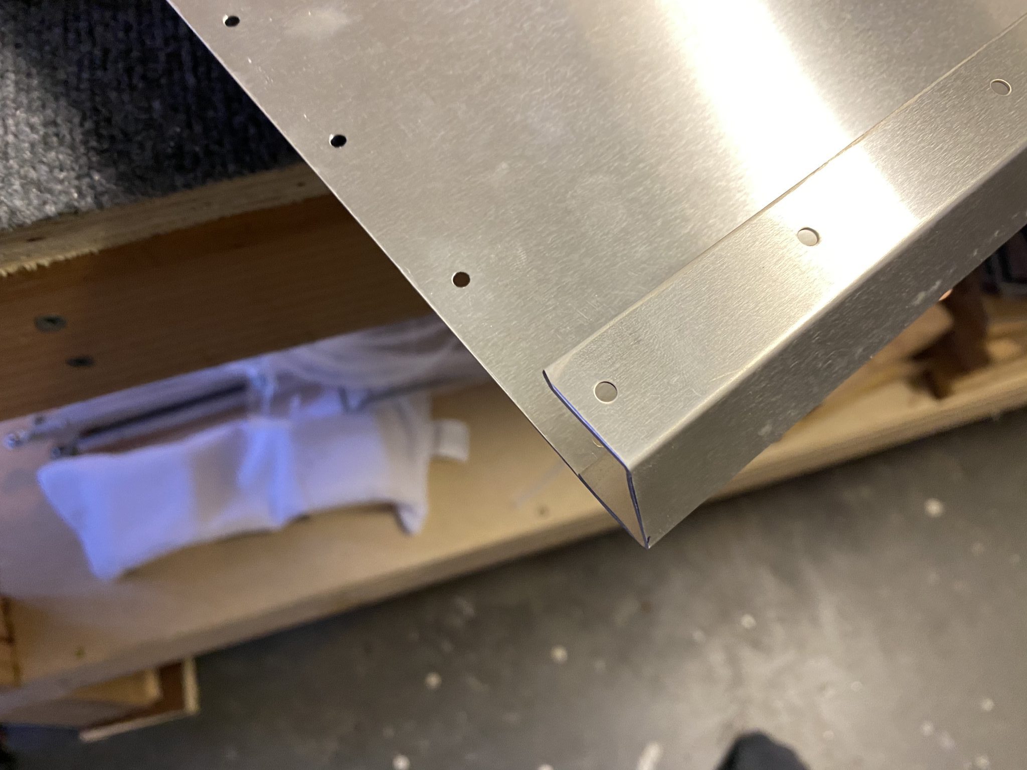
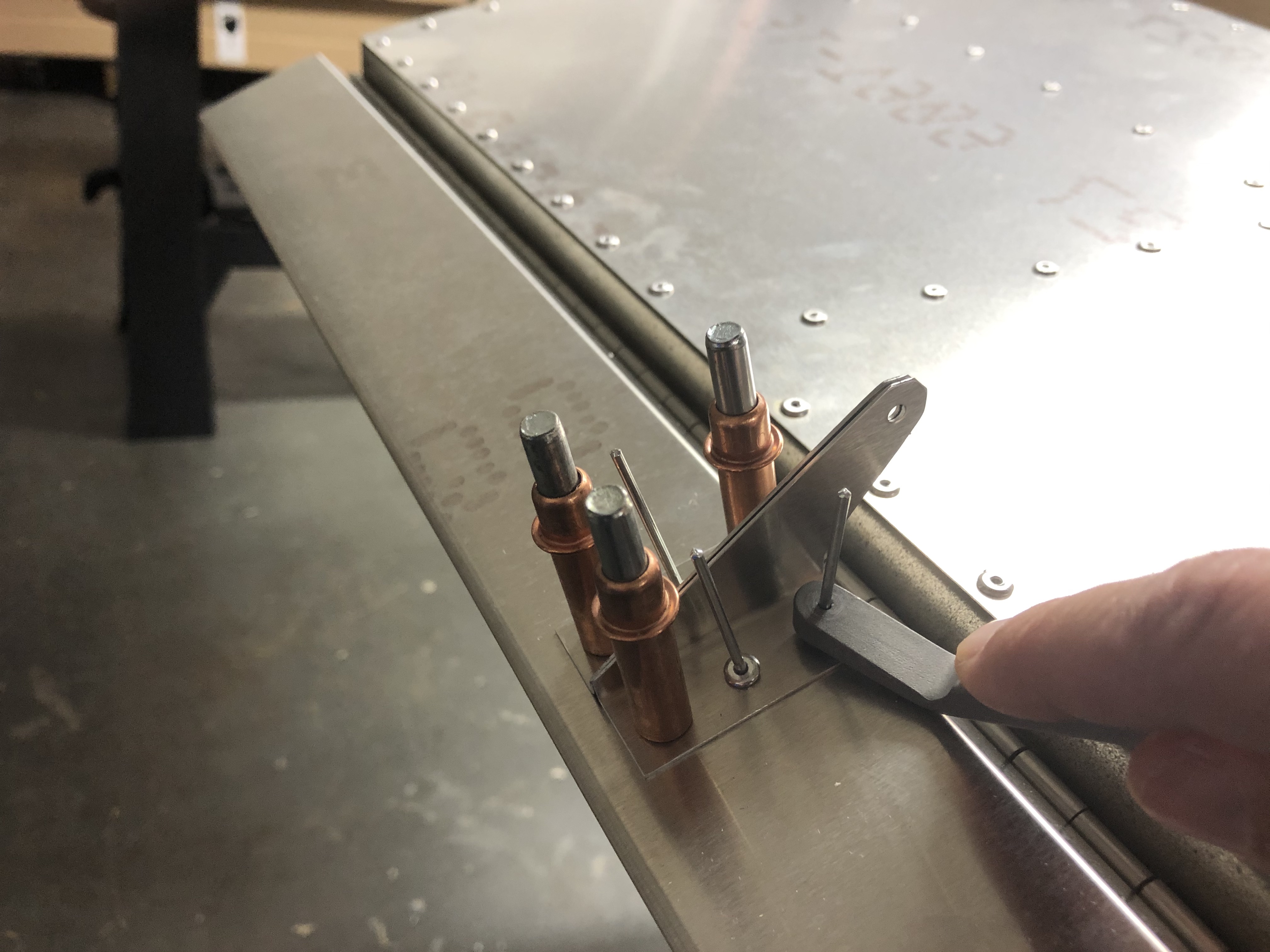
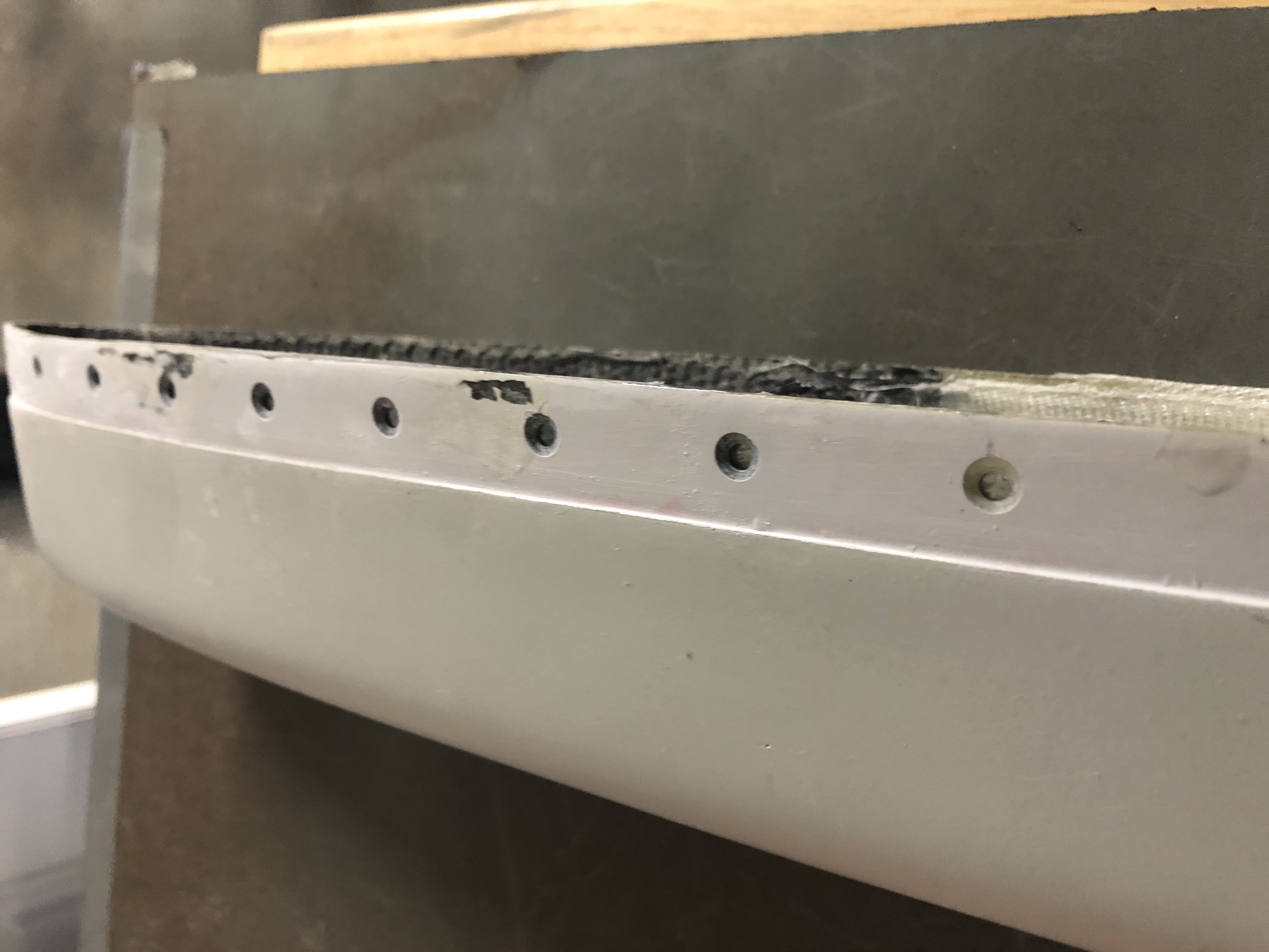
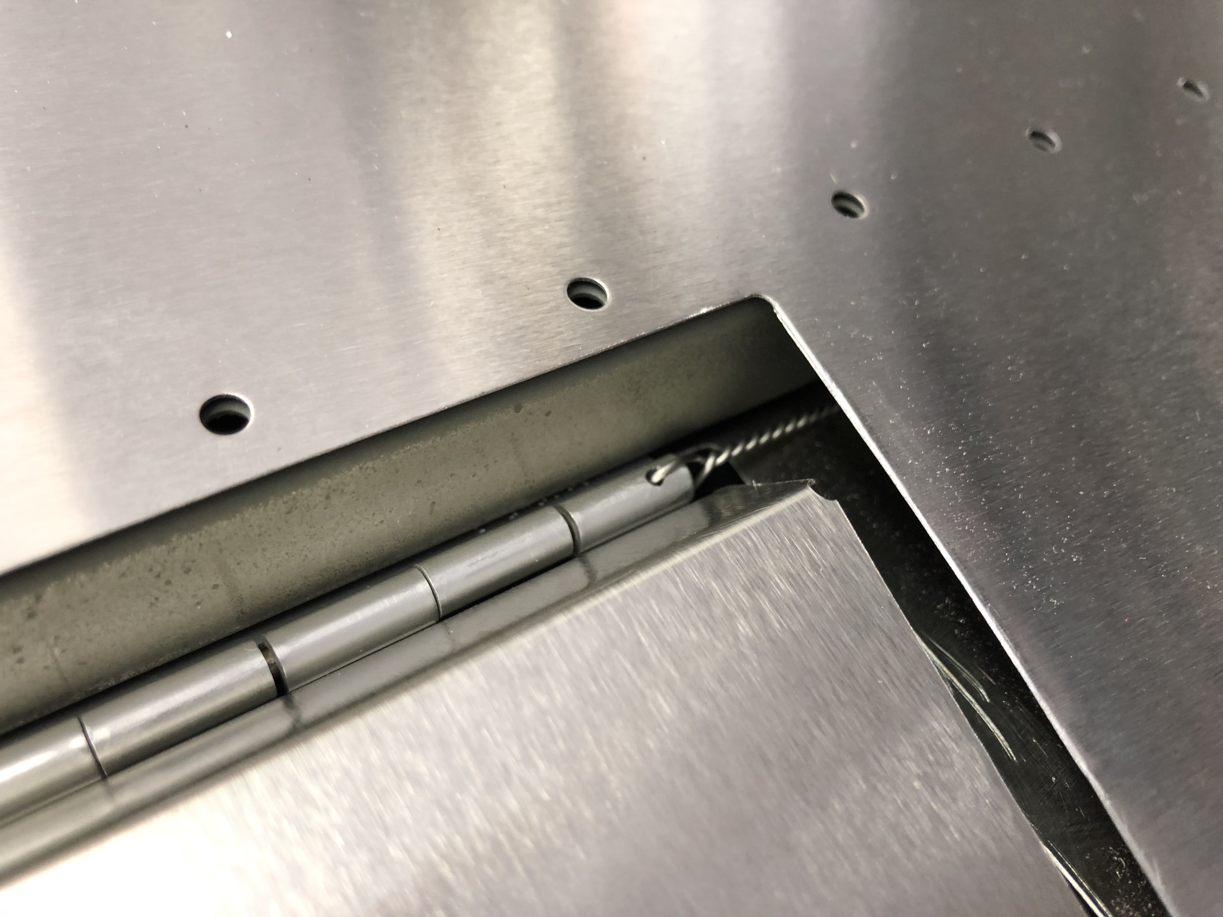
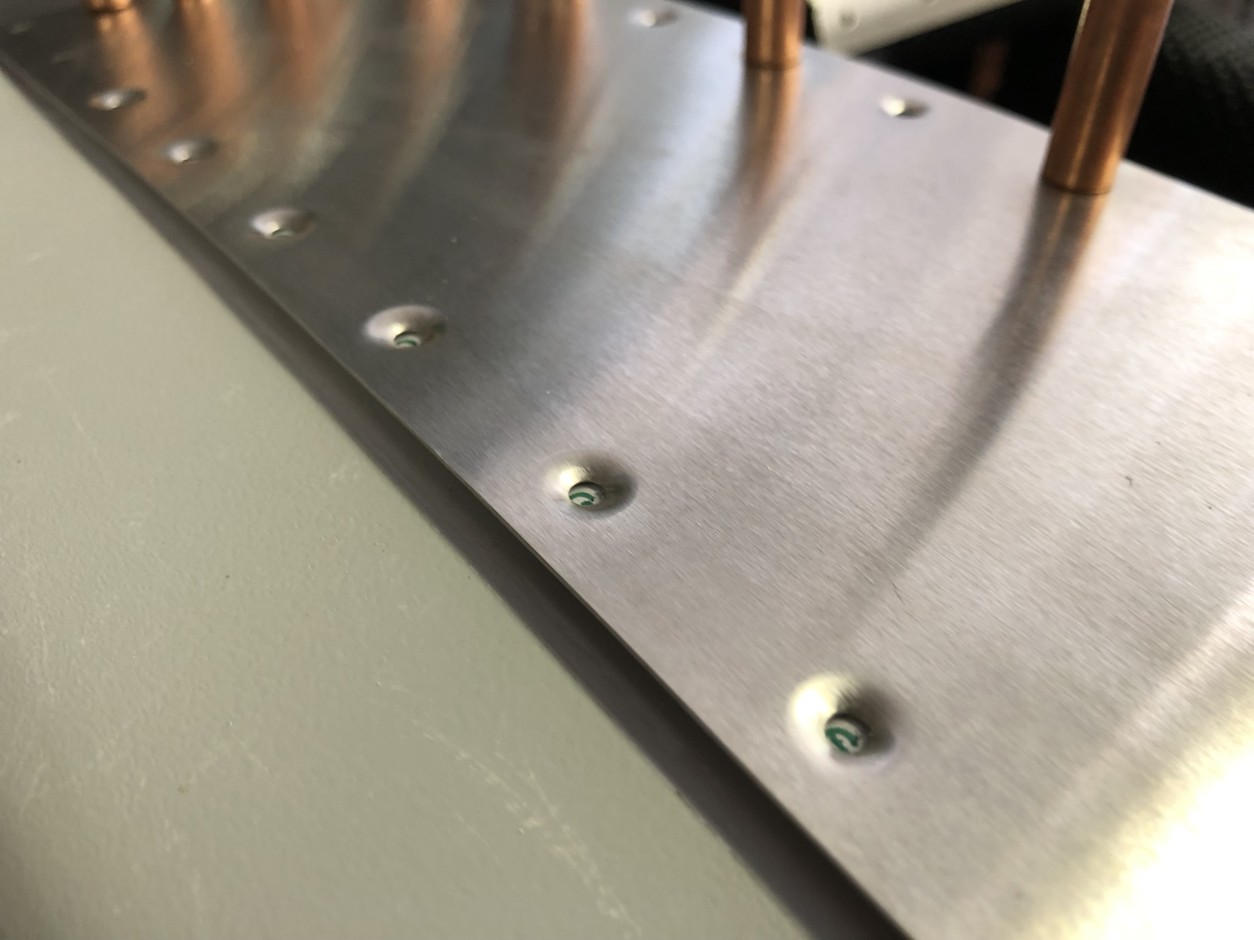
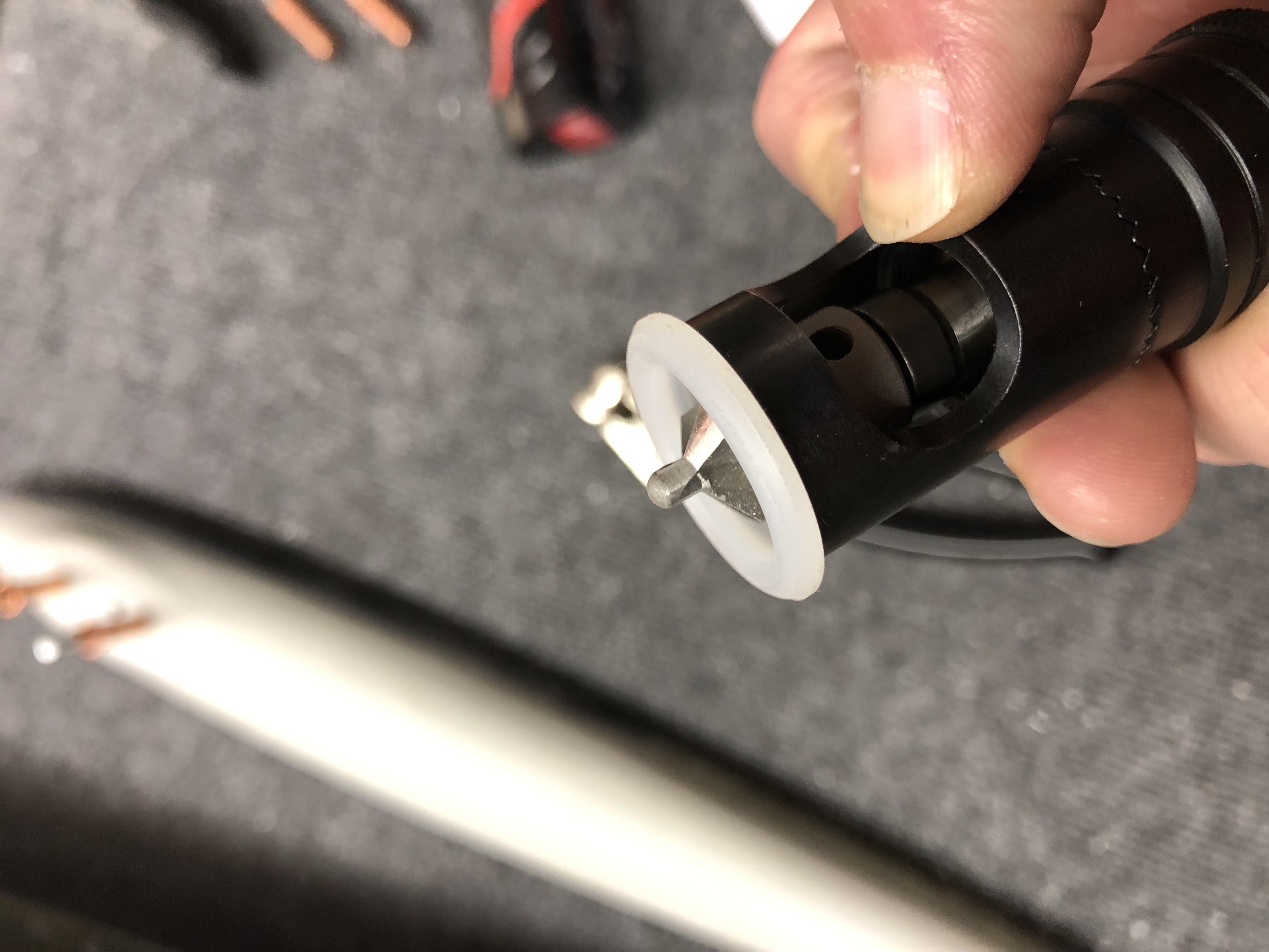
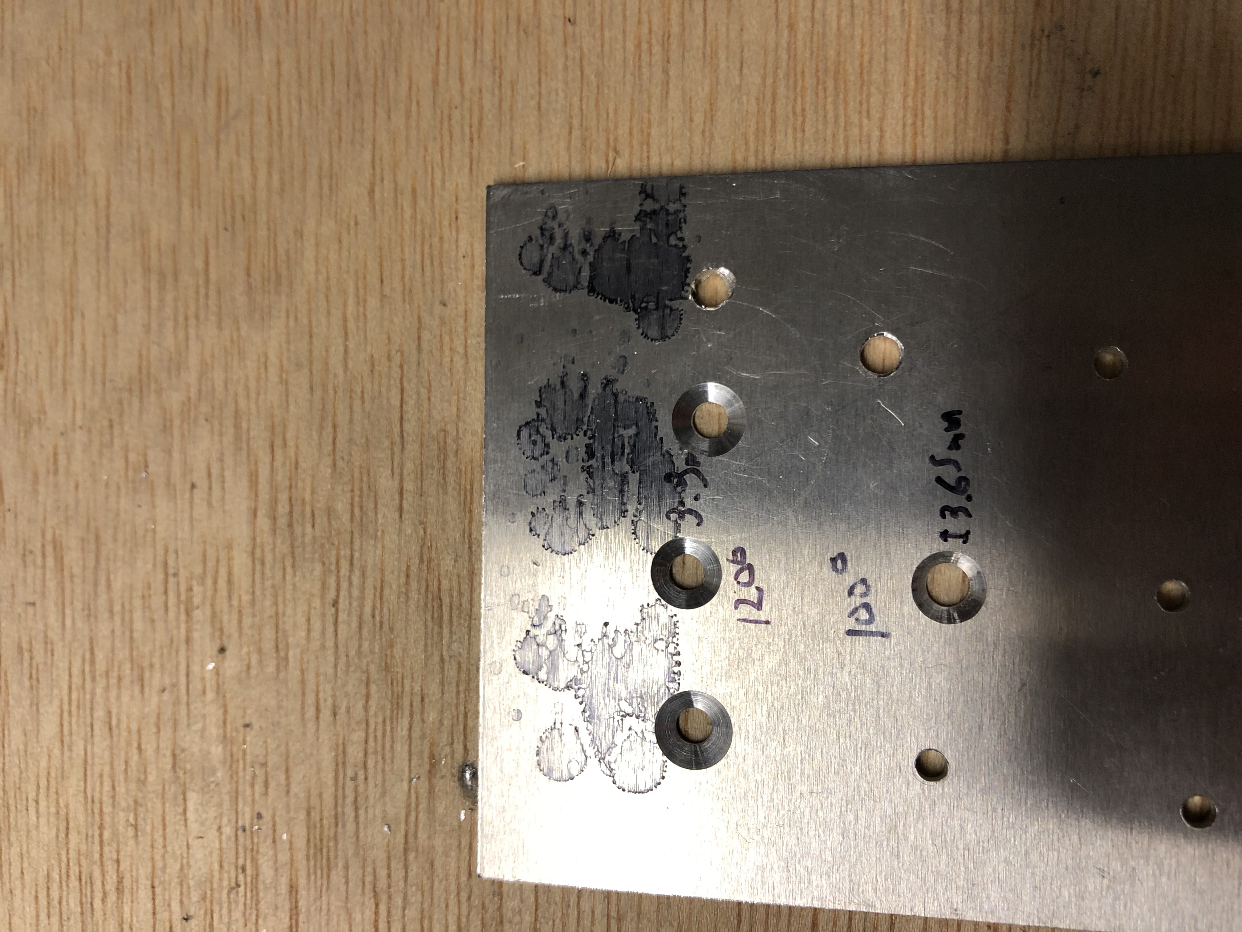
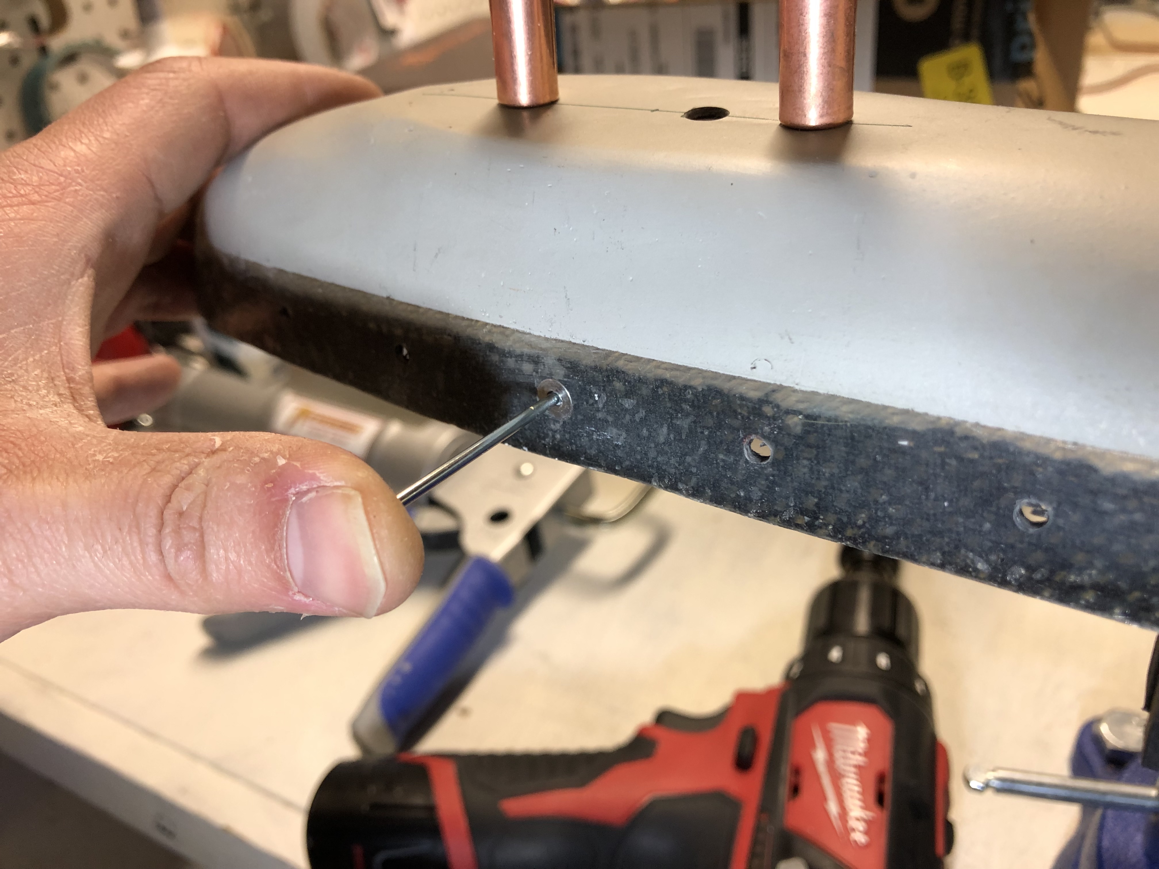
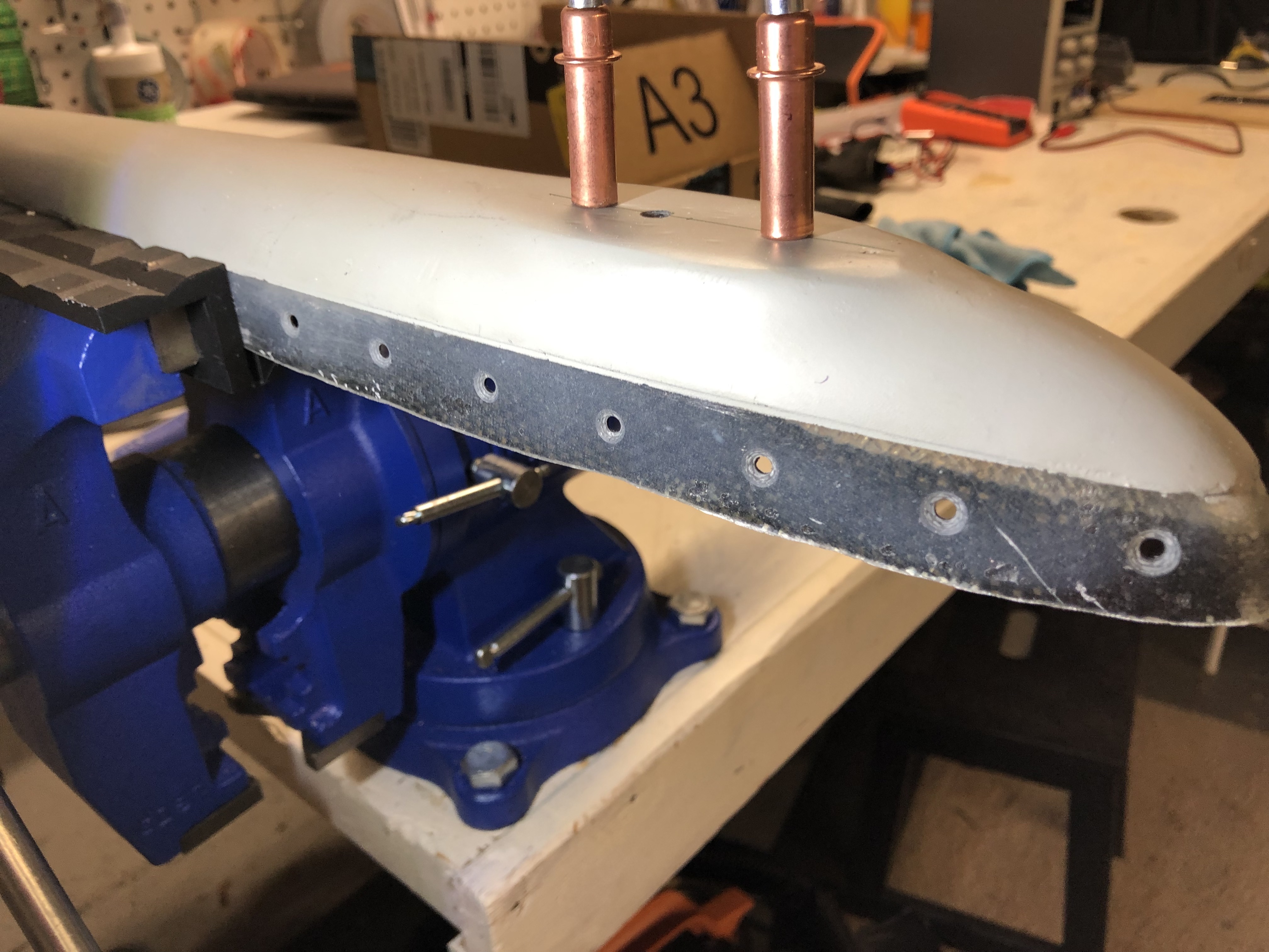
One of the ways to secure the hinge is to drill a small hole through the last part of the hinge and install a safety wire. My hinge was luckily cut in a way that makes this approach very easy to achieve. I got out a small drill bit, mounted the hinge in my bench vise and drilled a hole on each side so I could run a safety wire through it.
EAA diagram to safety the hinge Hinge mounted in my bench vise to drill the hole for the safety wire Hole drilled for the safety wire Safety wire in place to test free movement while connected to the Elevator

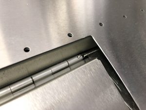
Using the safety wire approach makes it easy to still remove it in the future, but ensures that the pin stays securely in the hinge.
Testing free movement of the trim tab with the safety wire in place

Fitting the left side fiberglass tip

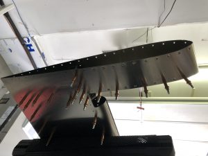
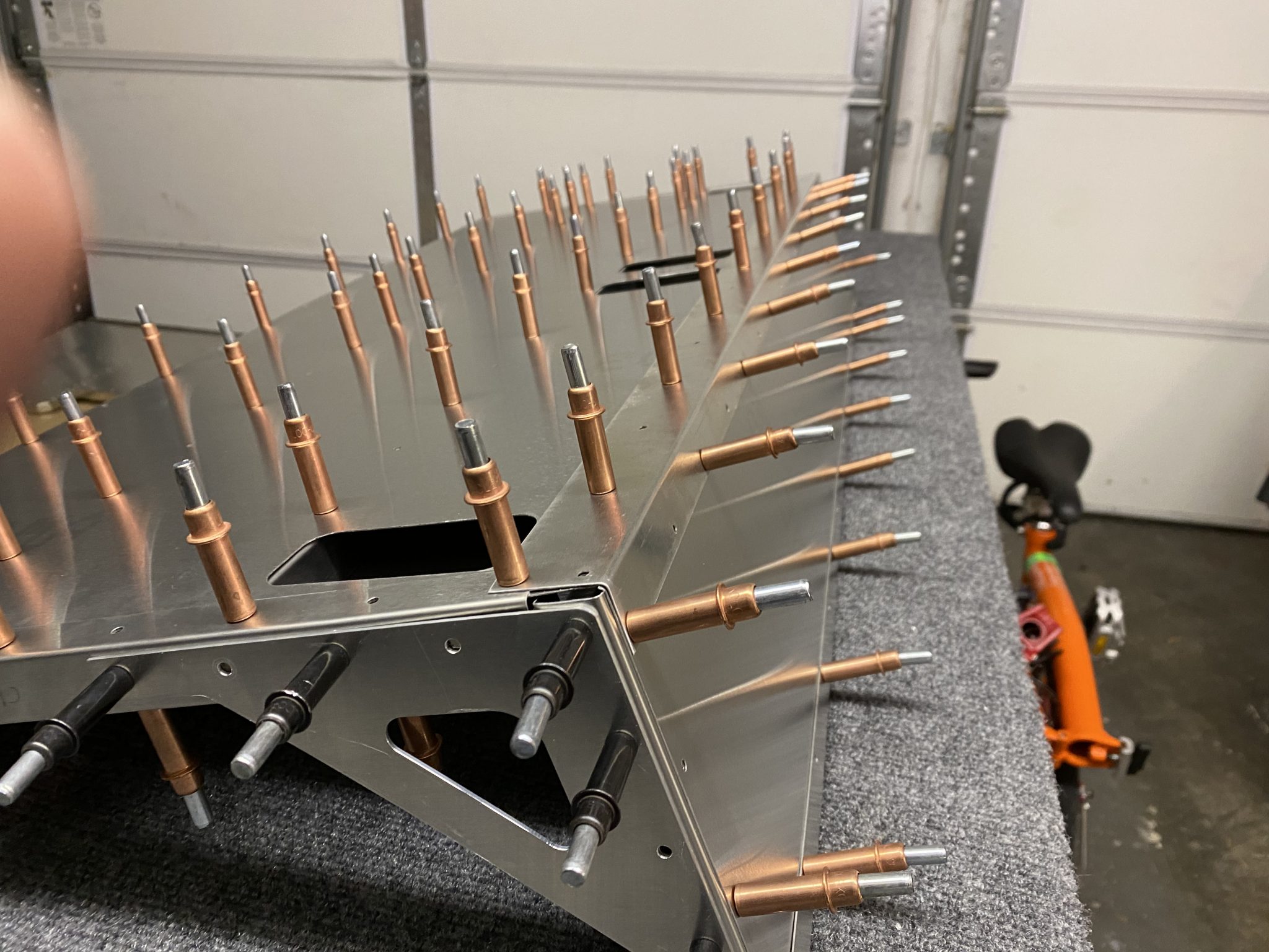
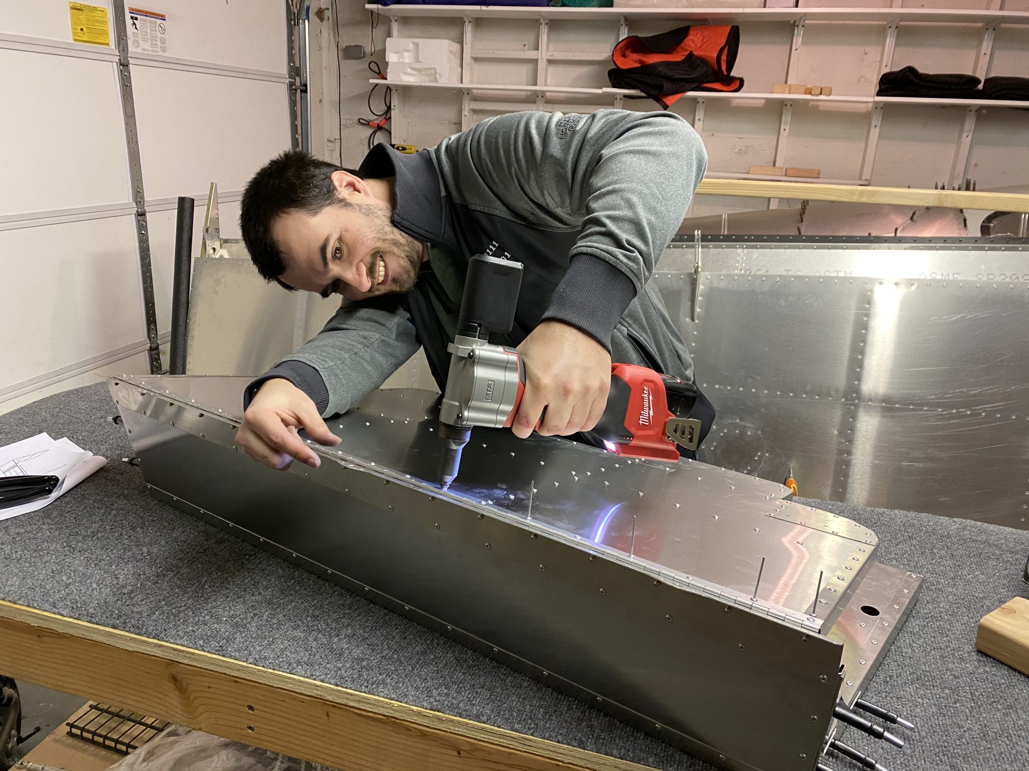
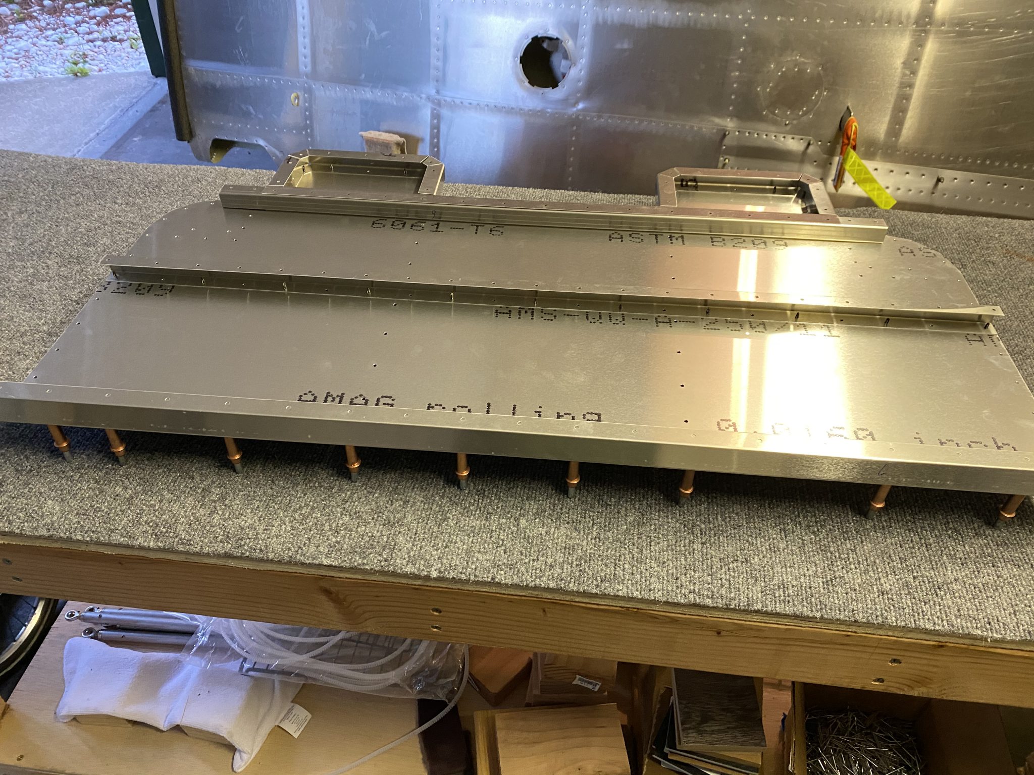
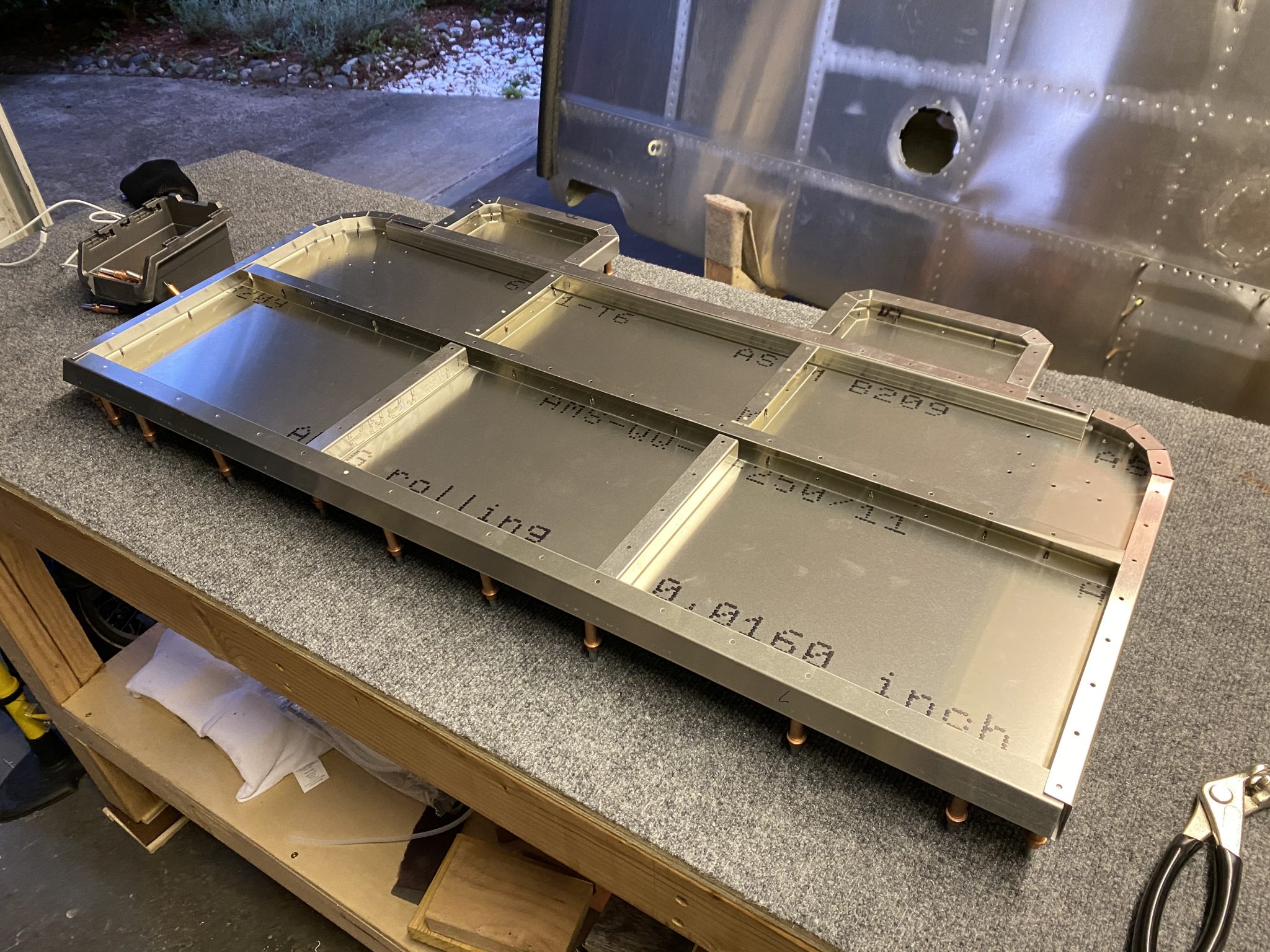
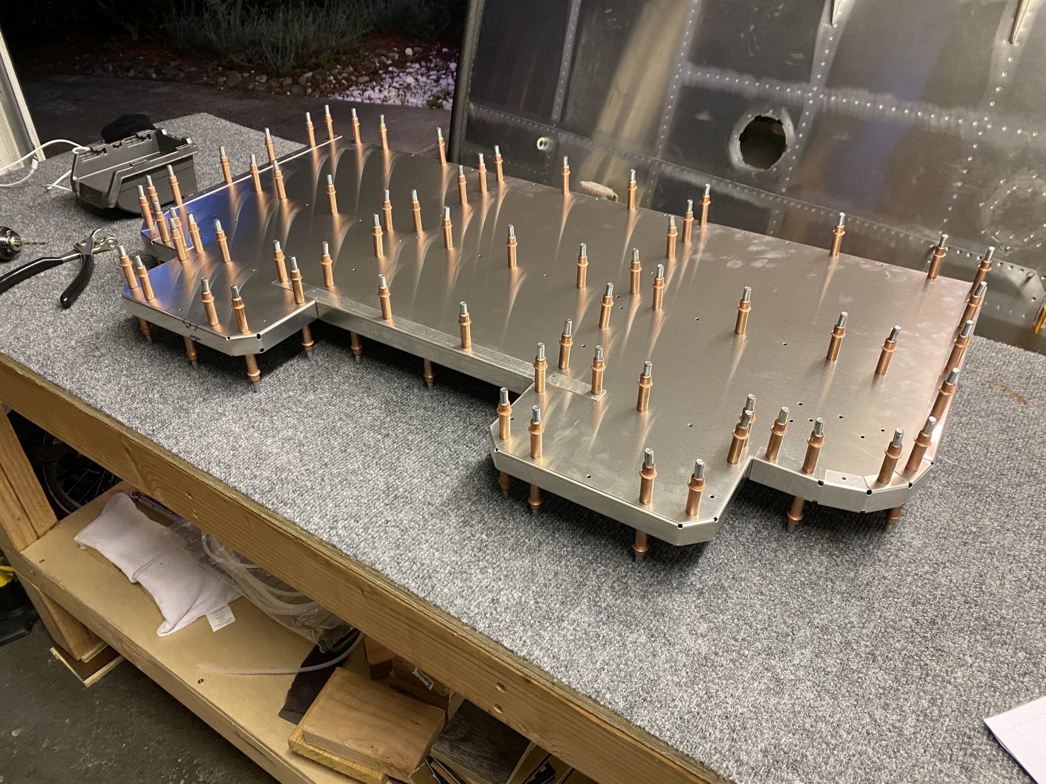
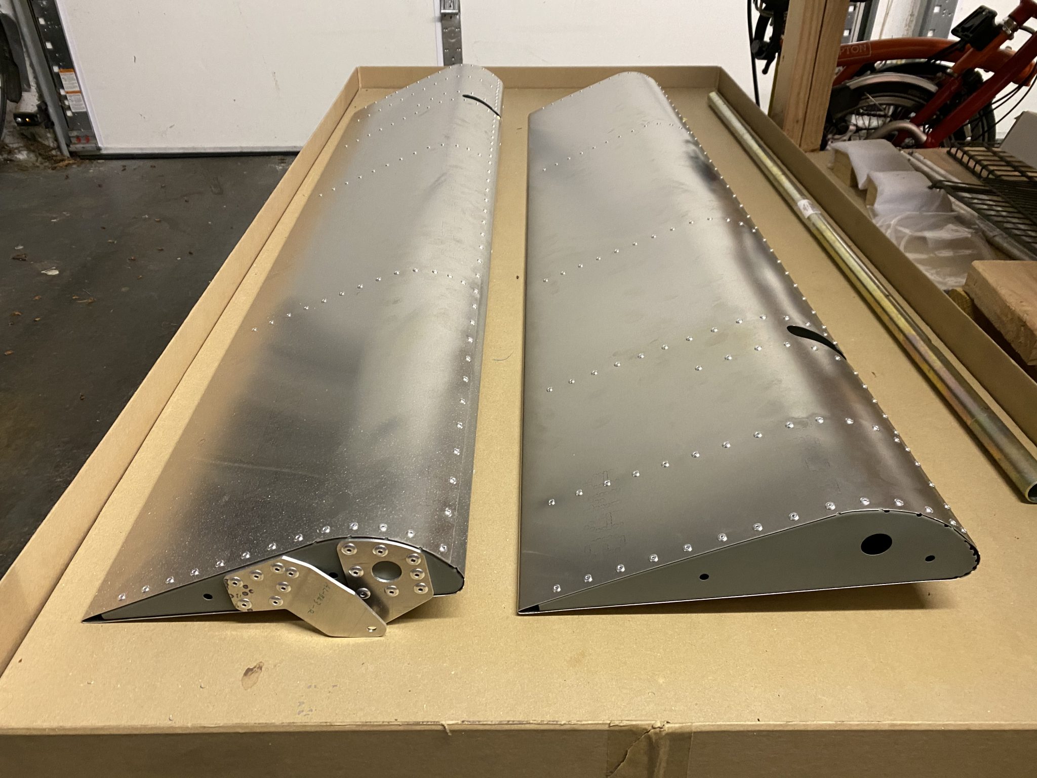
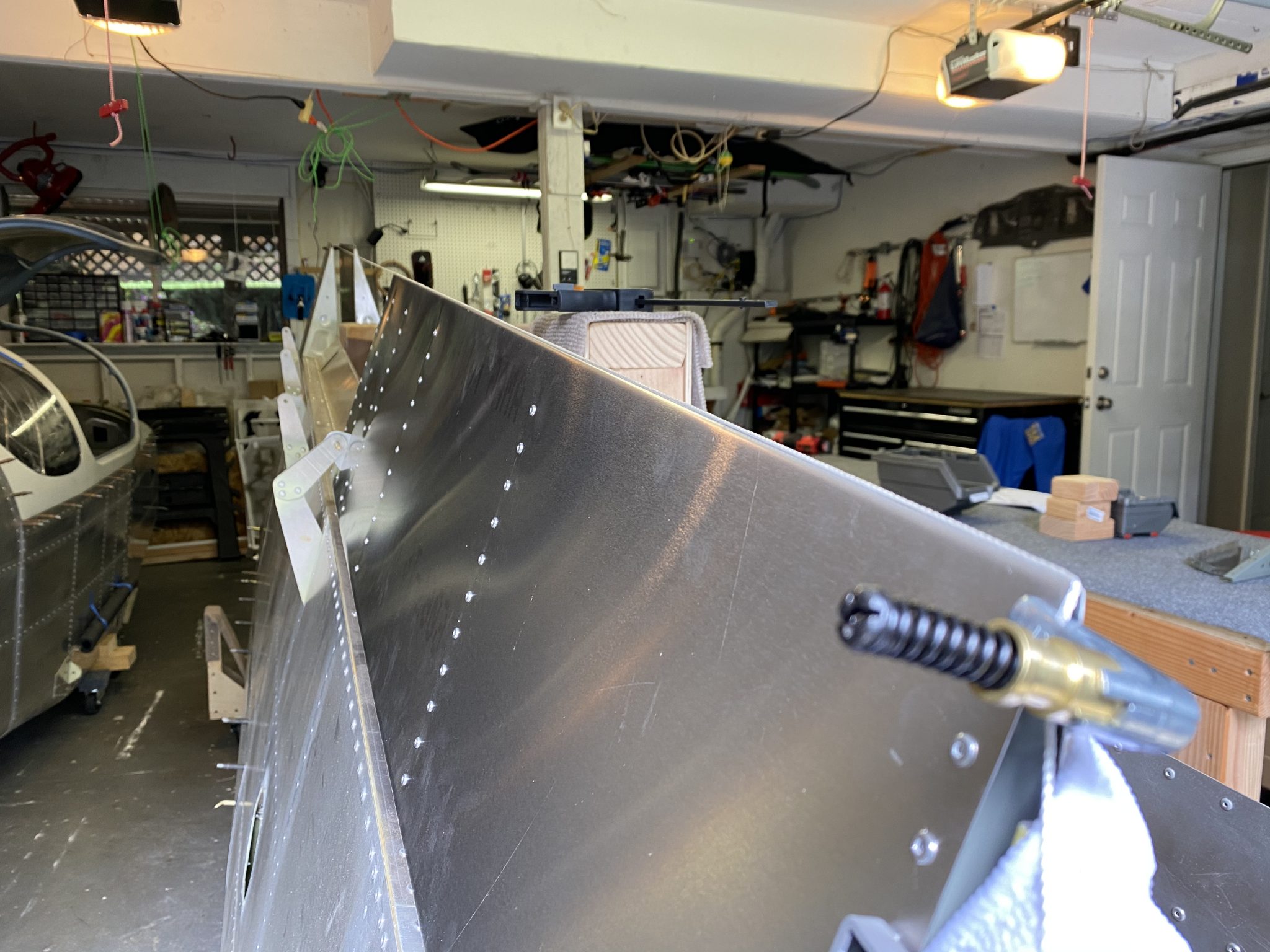
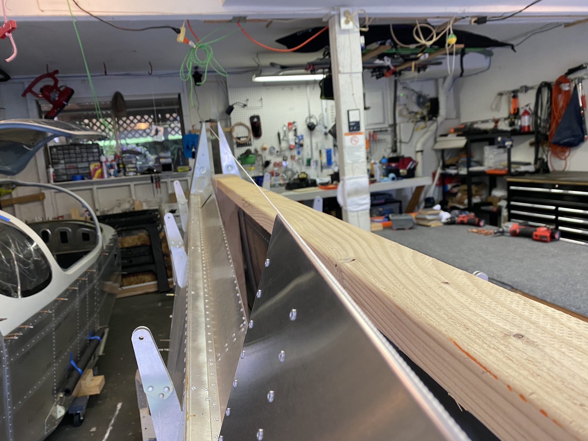
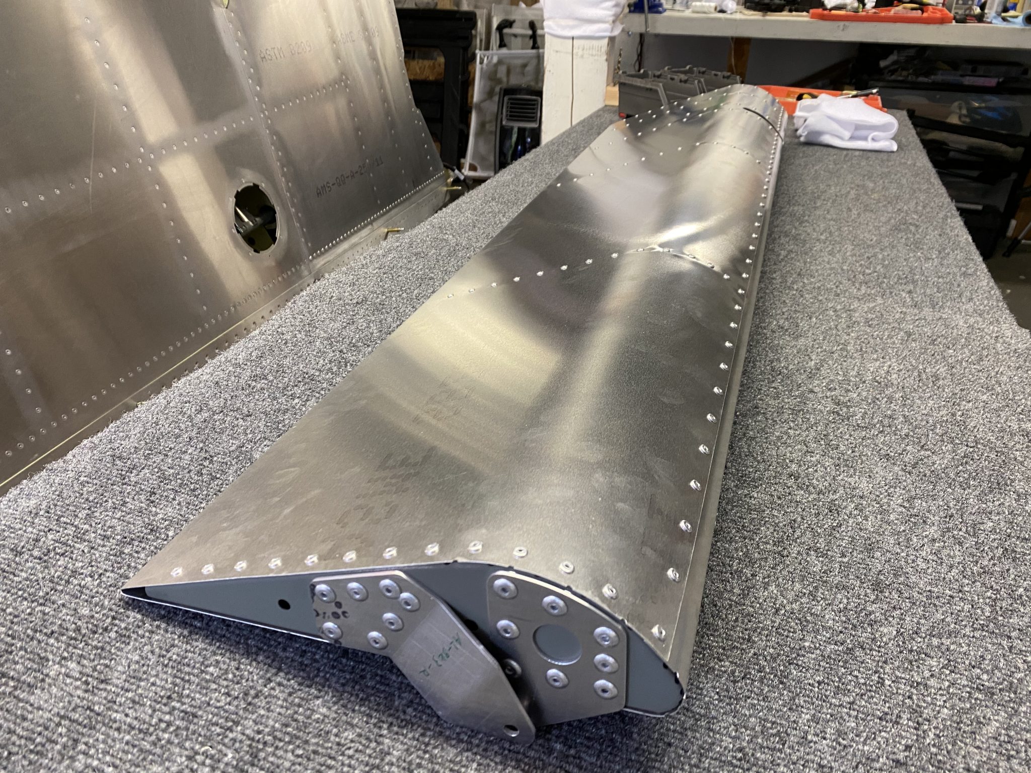
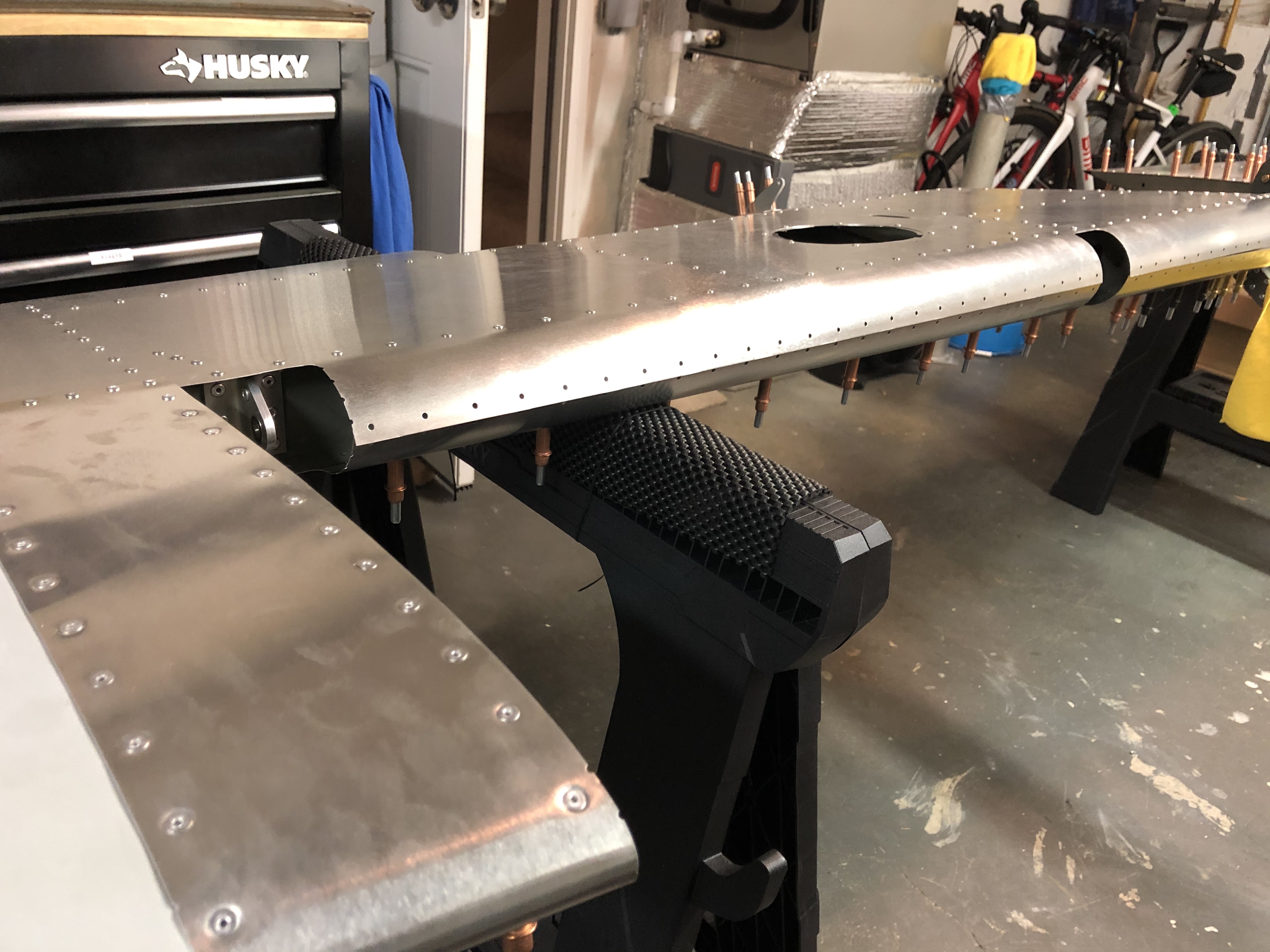
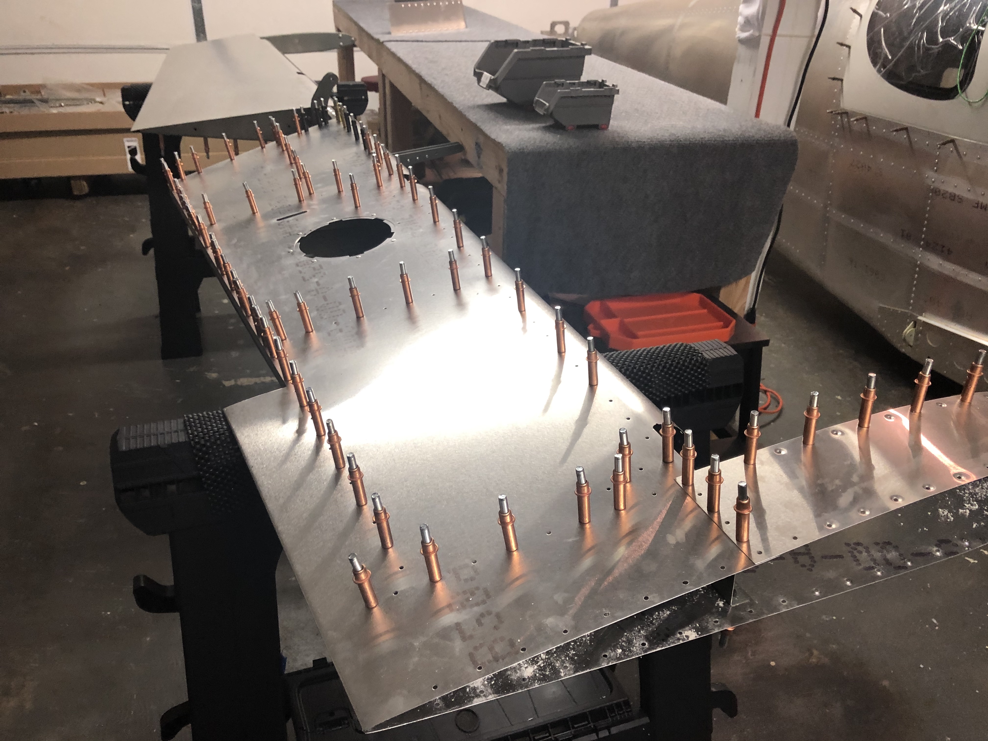
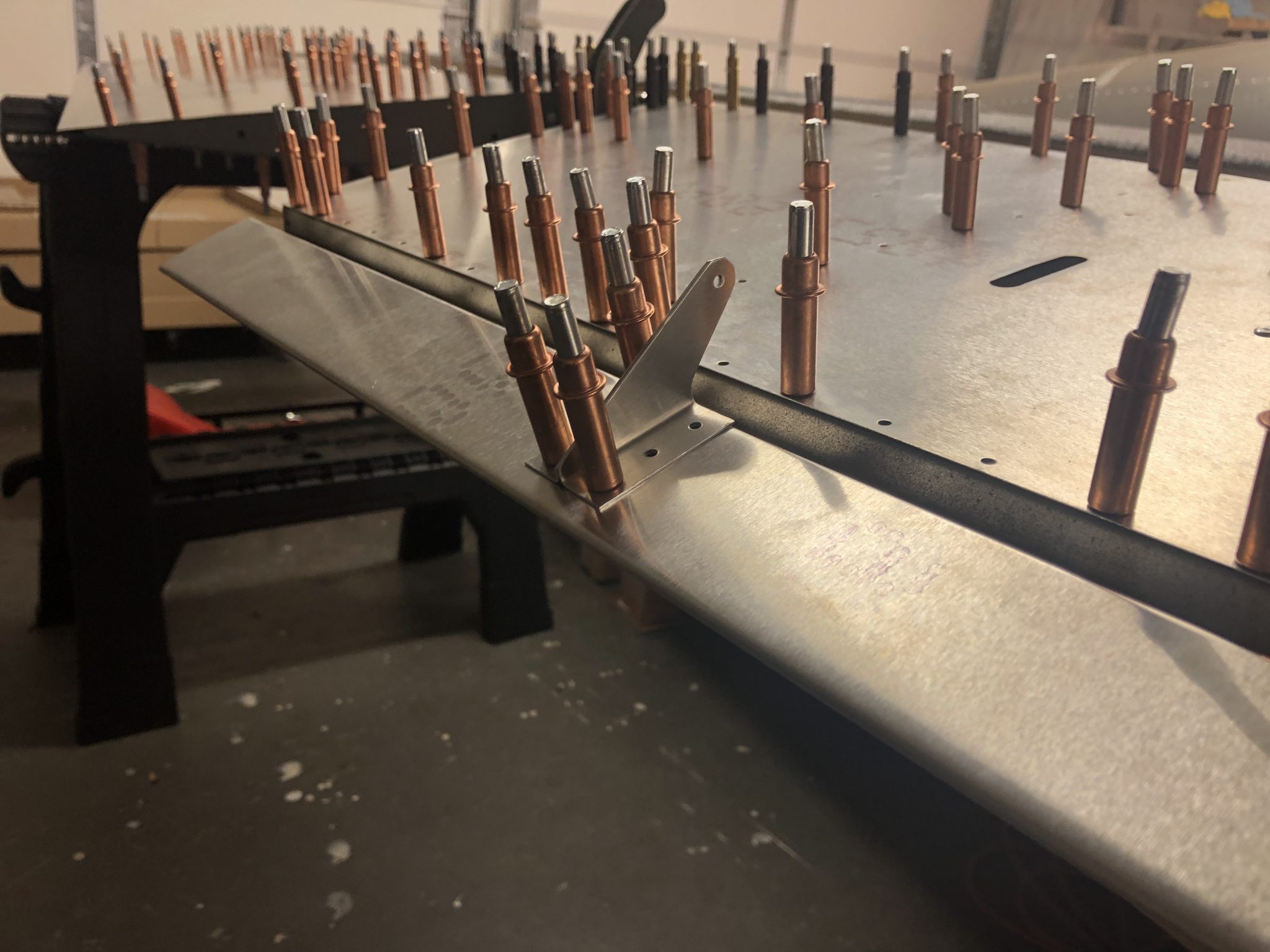
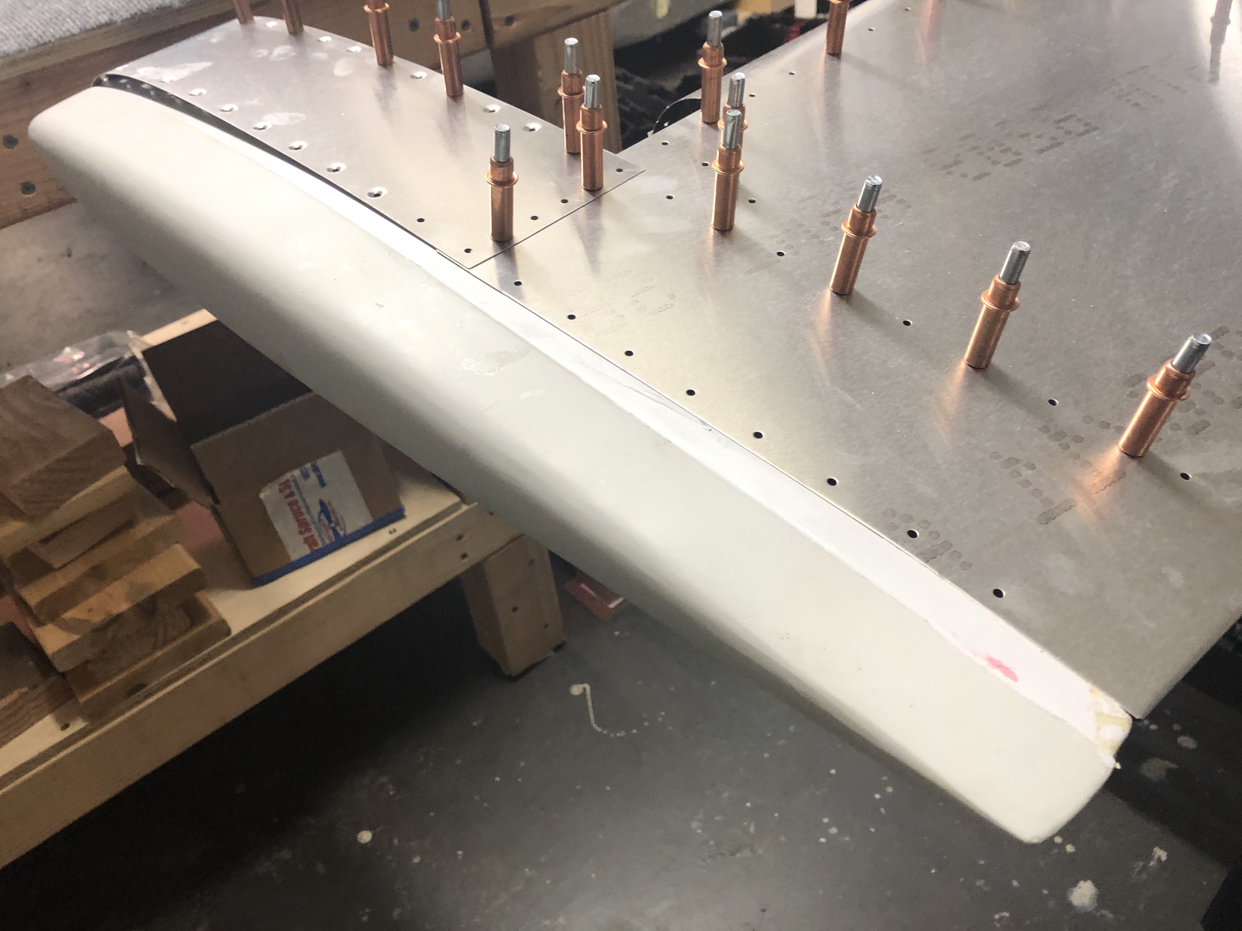
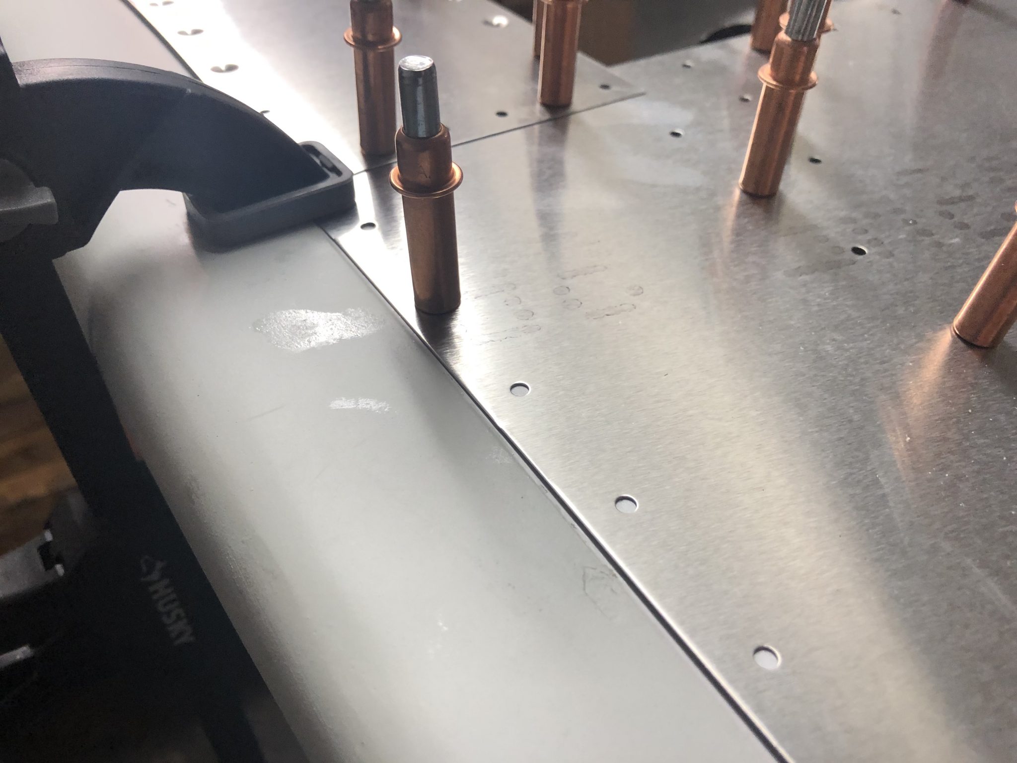
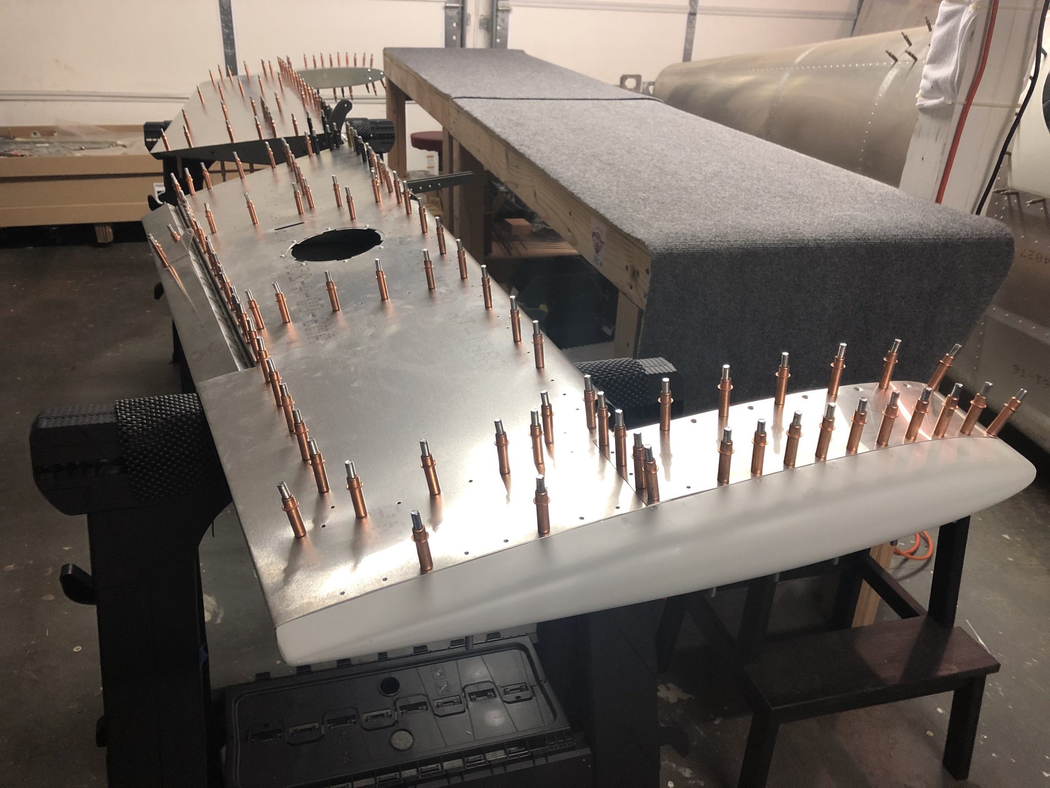
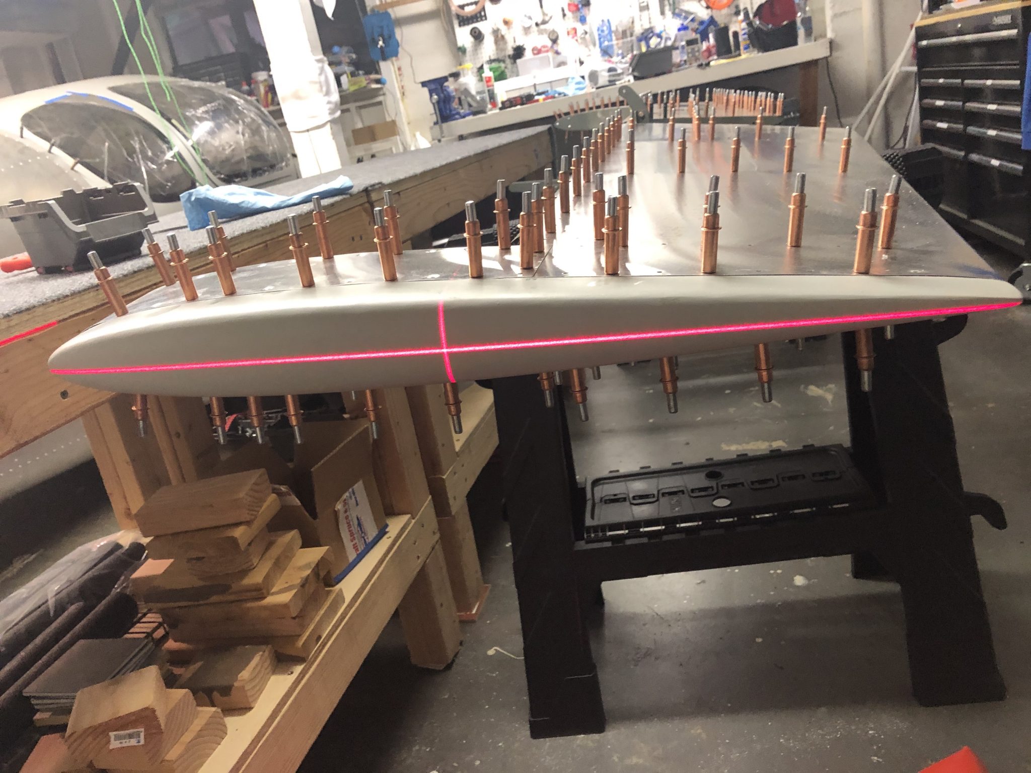
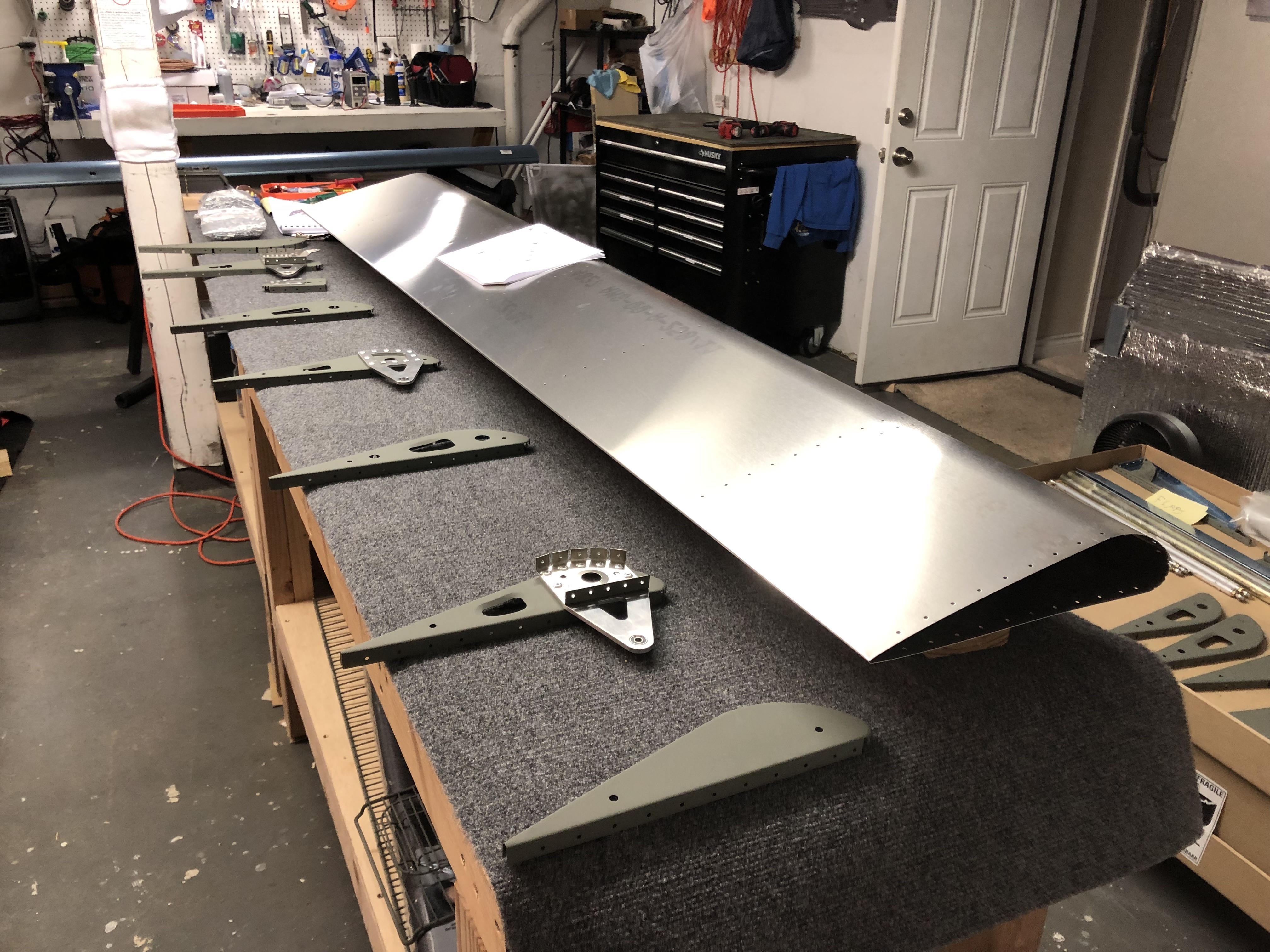
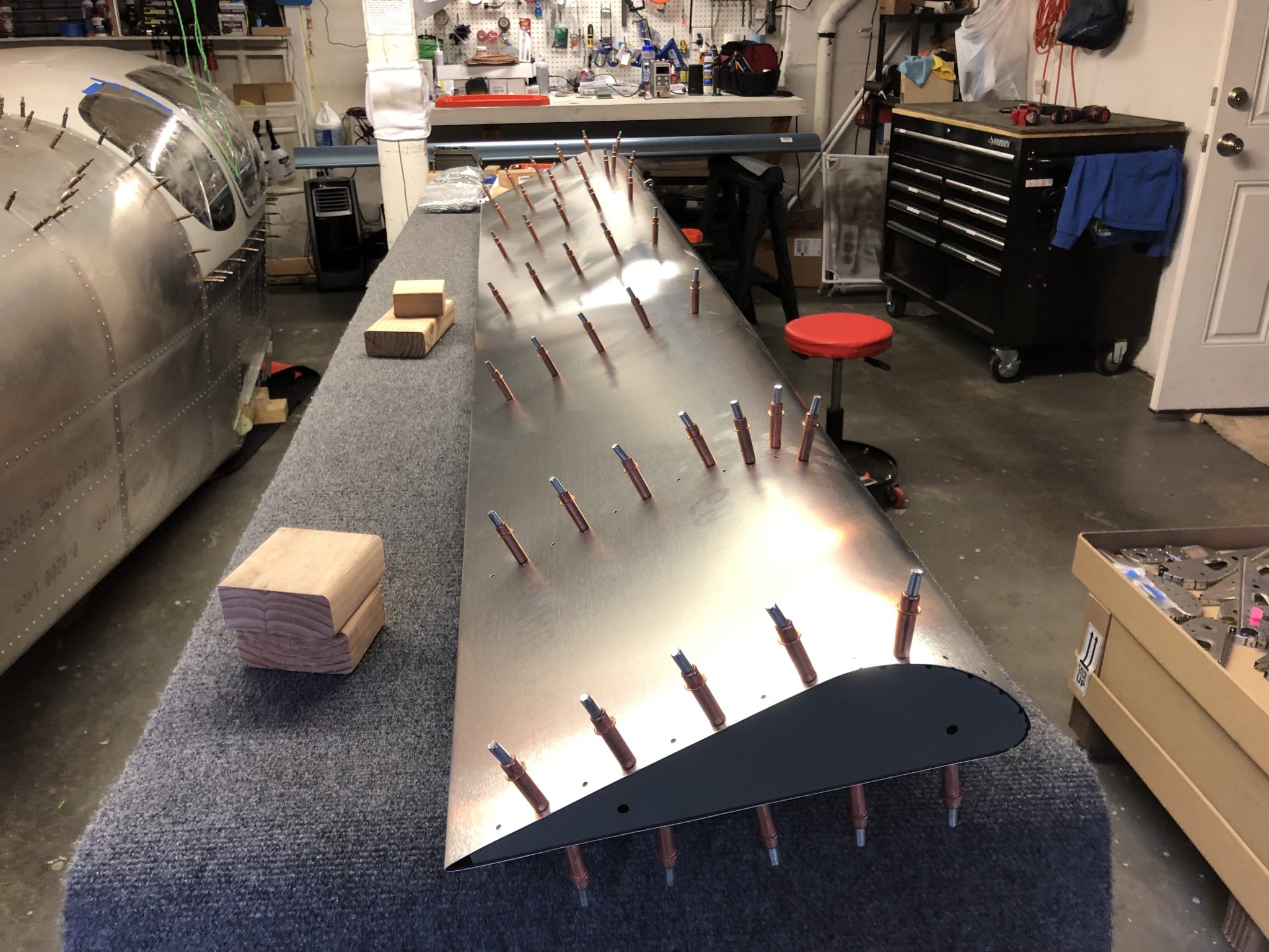
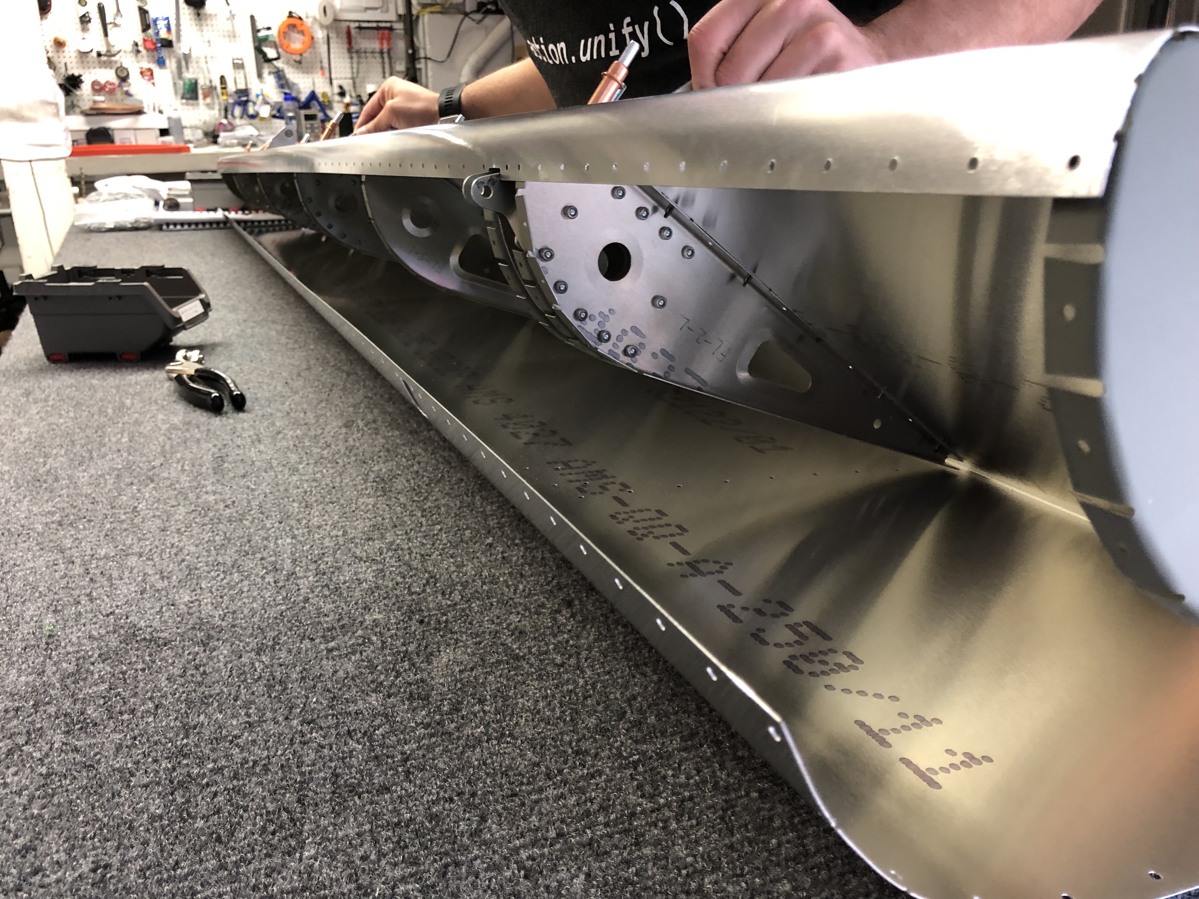
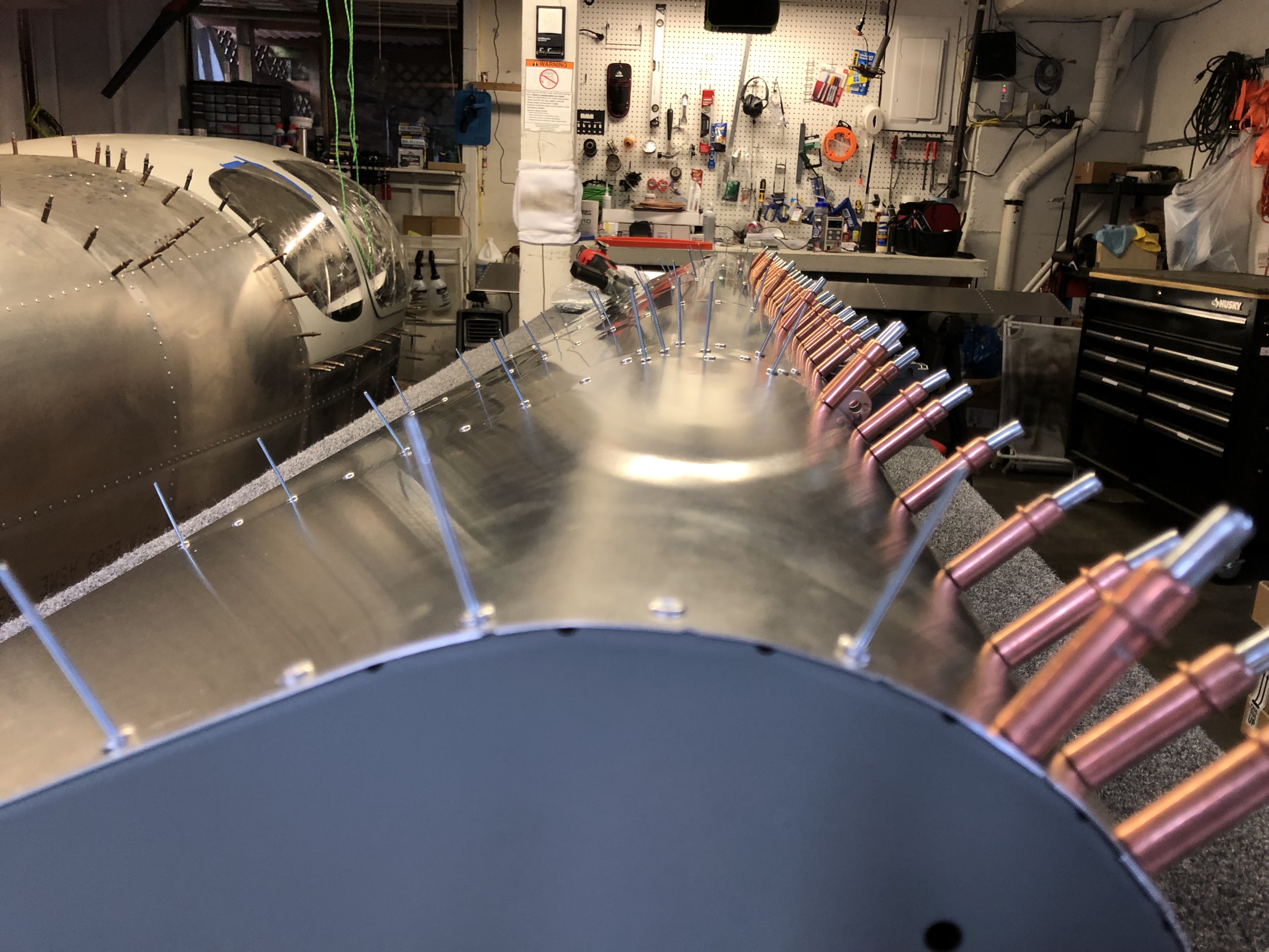
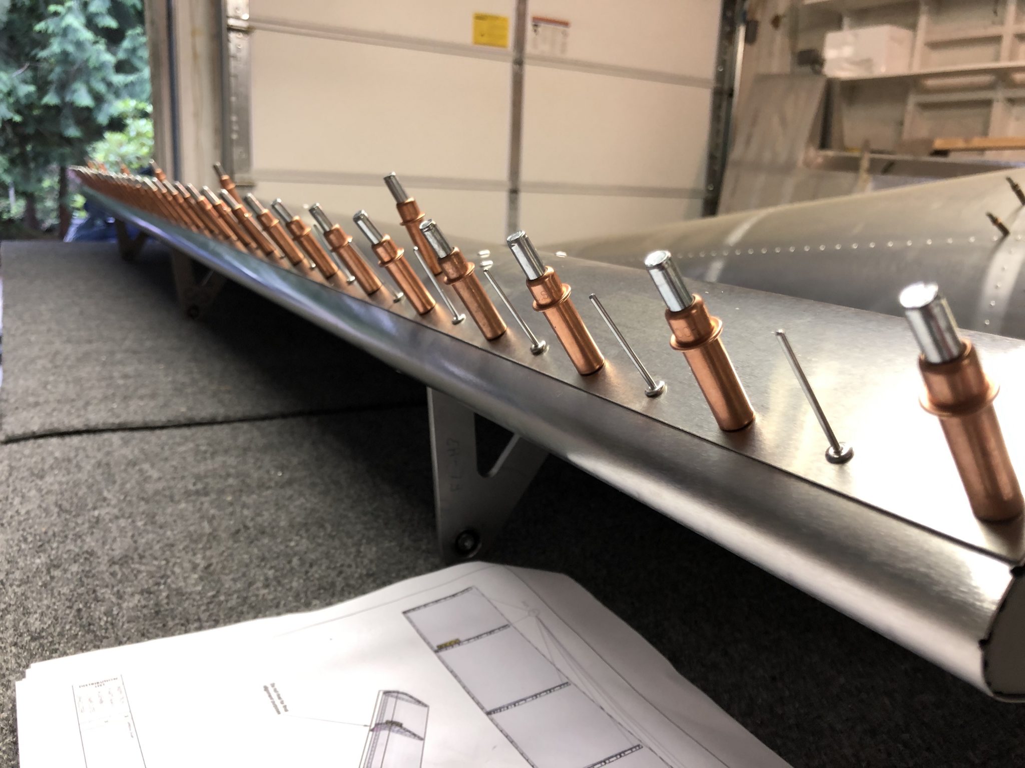
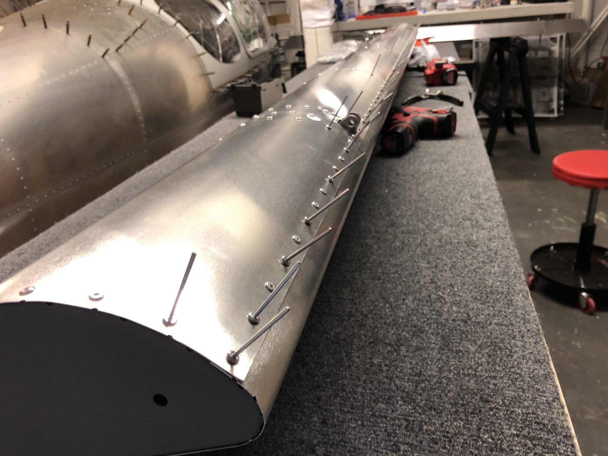
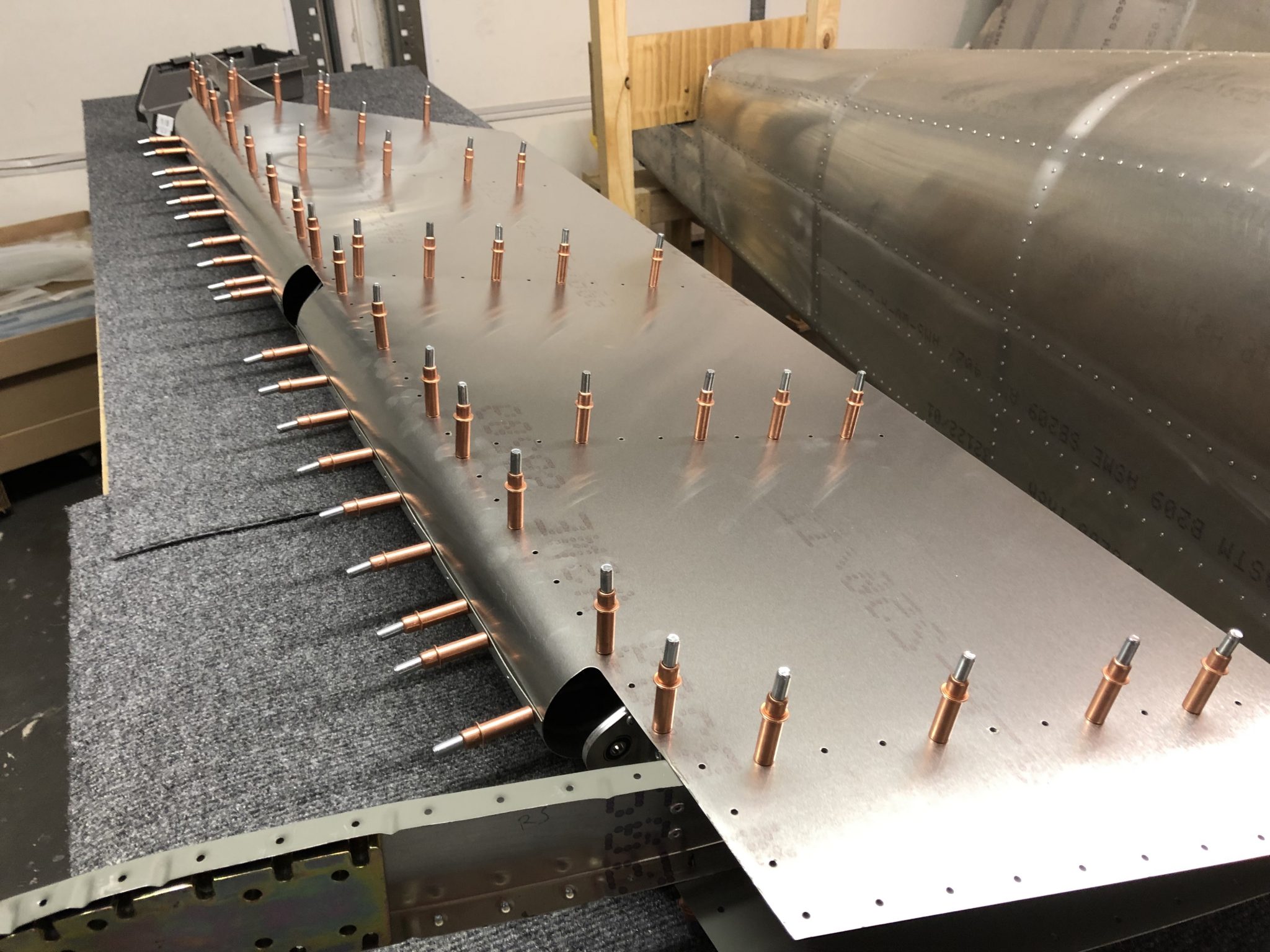
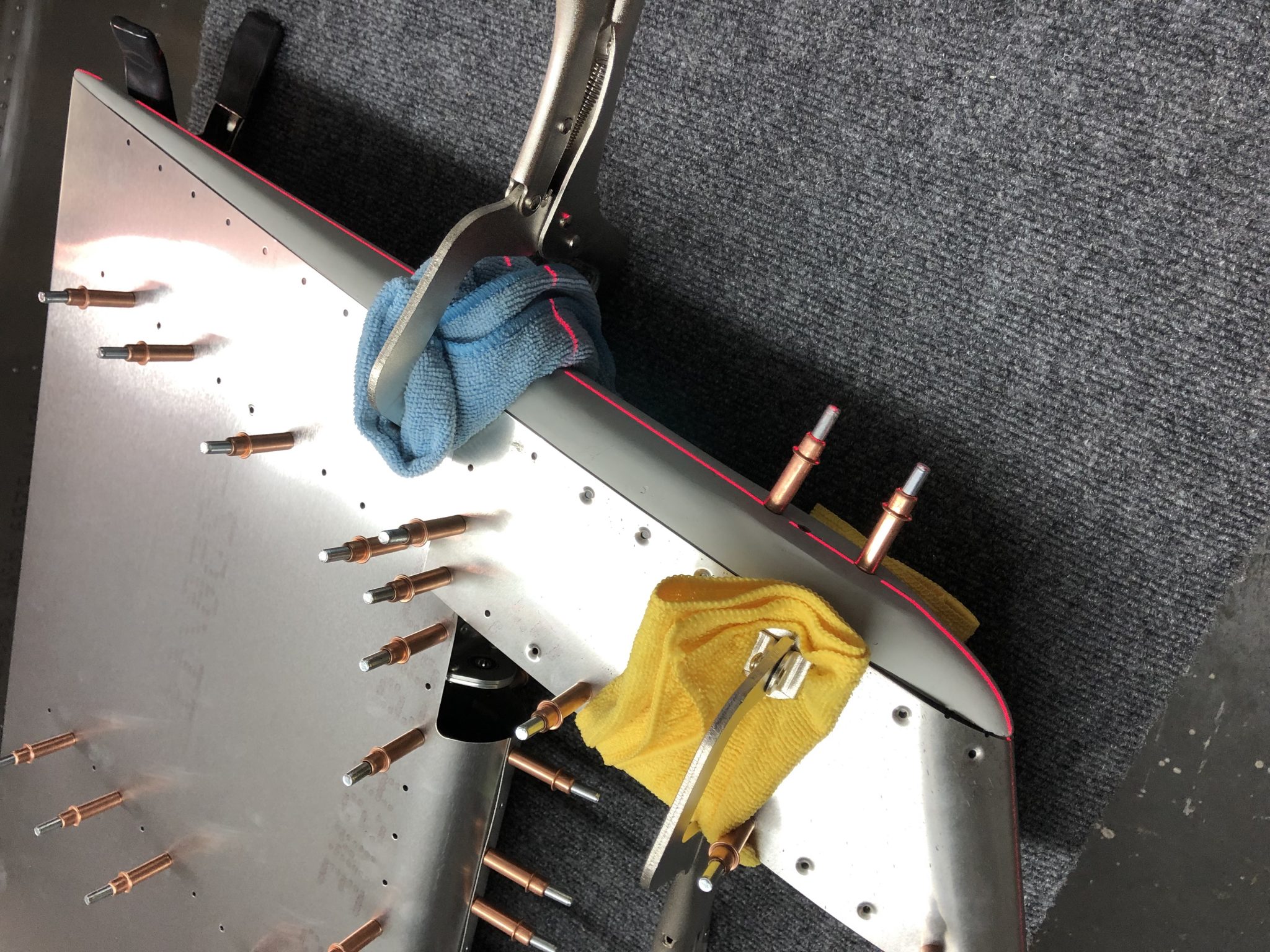
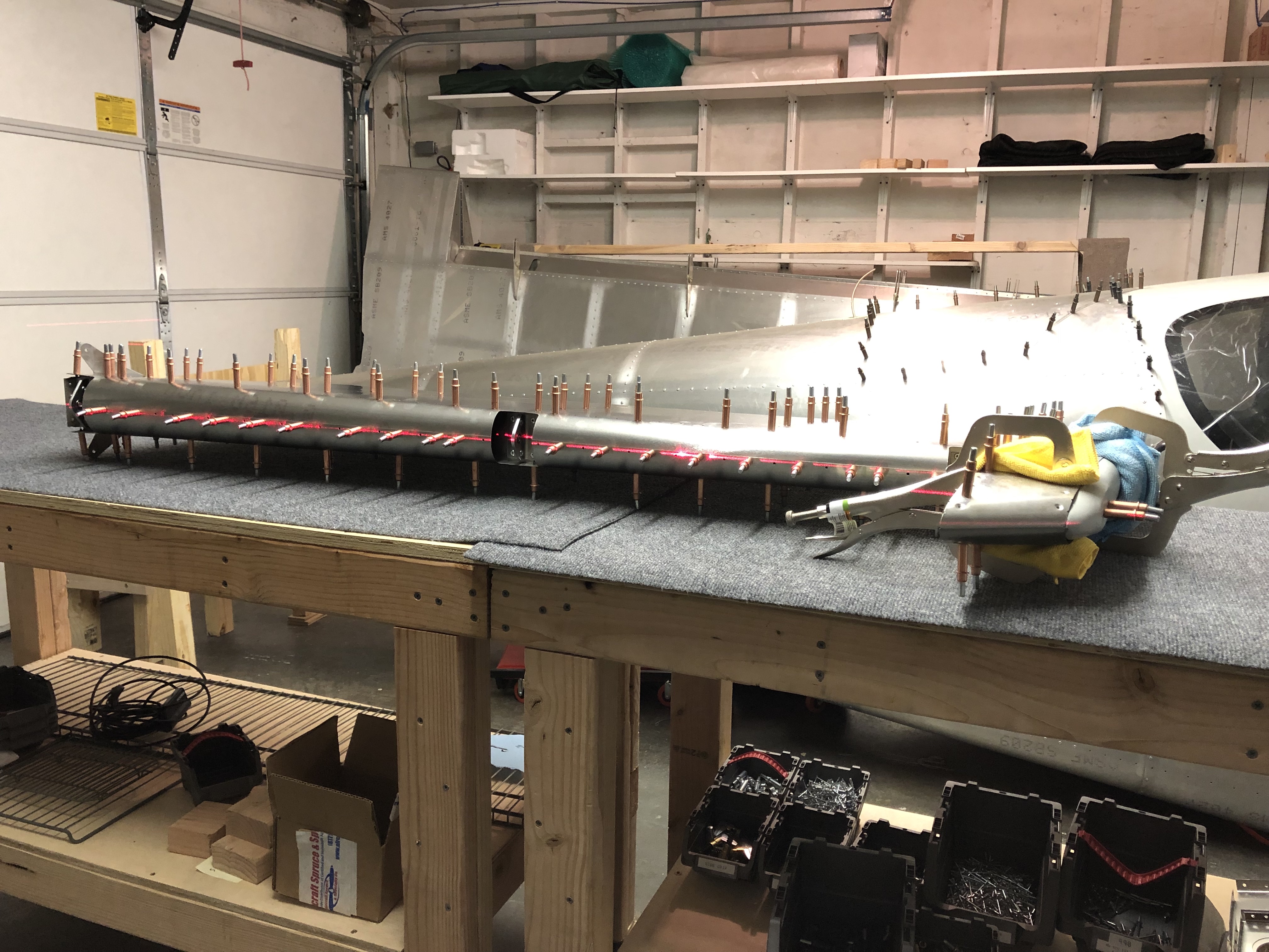
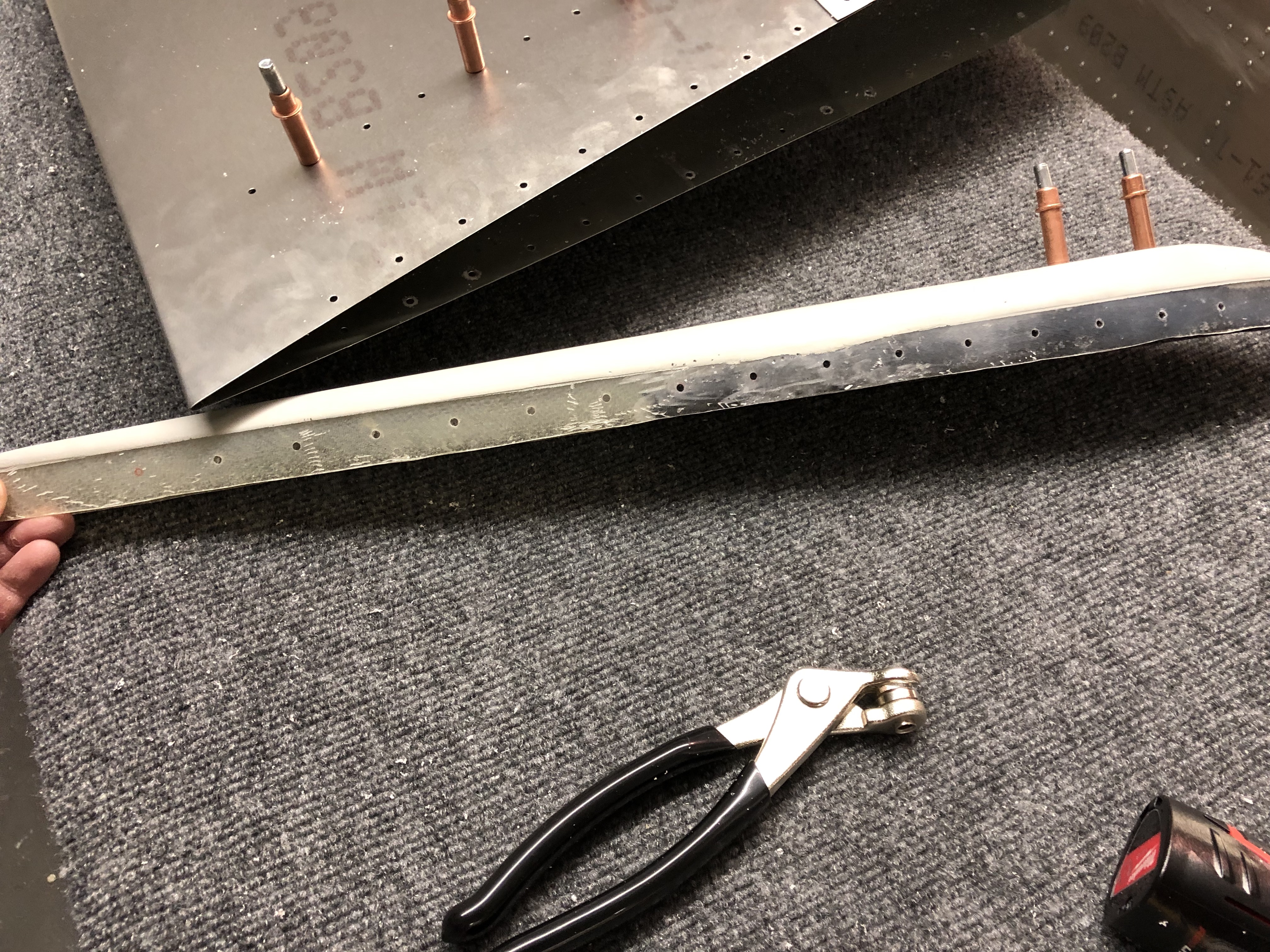
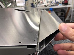
For the last part of the day, I started on fitting the last part of the skin and the fiberglass tips. Since this requires moving around the tip from both sides, I moved the Elevator over onto some saw horses so I could access the bottom more easily.

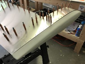
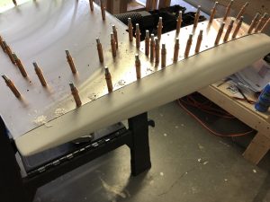
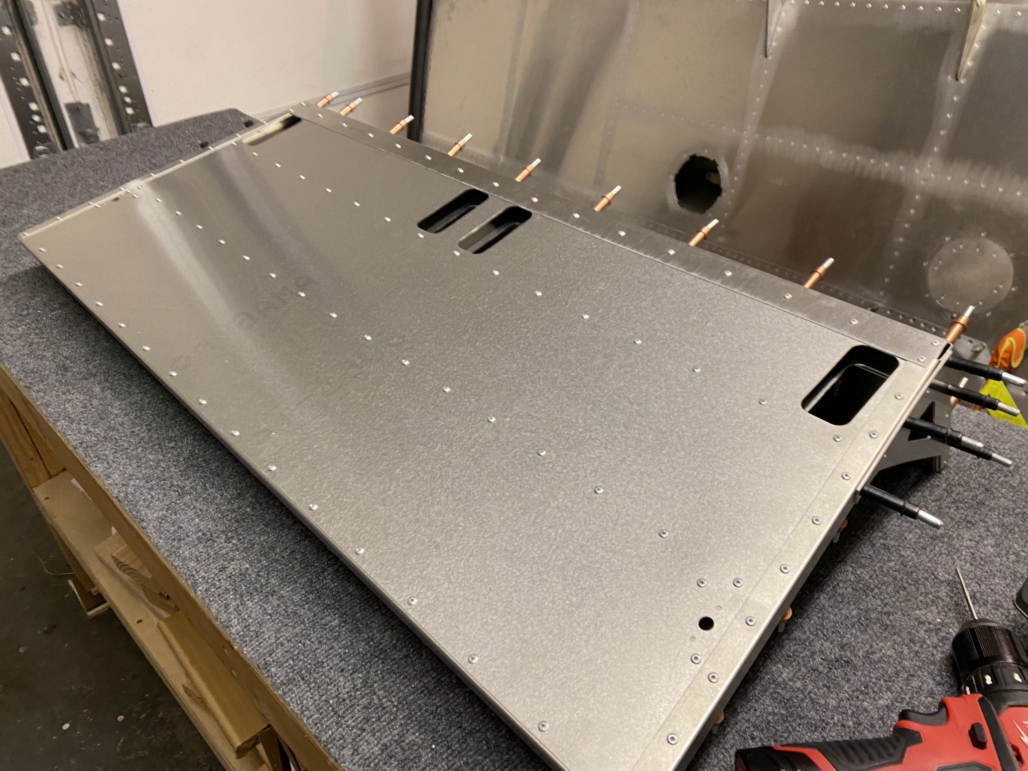
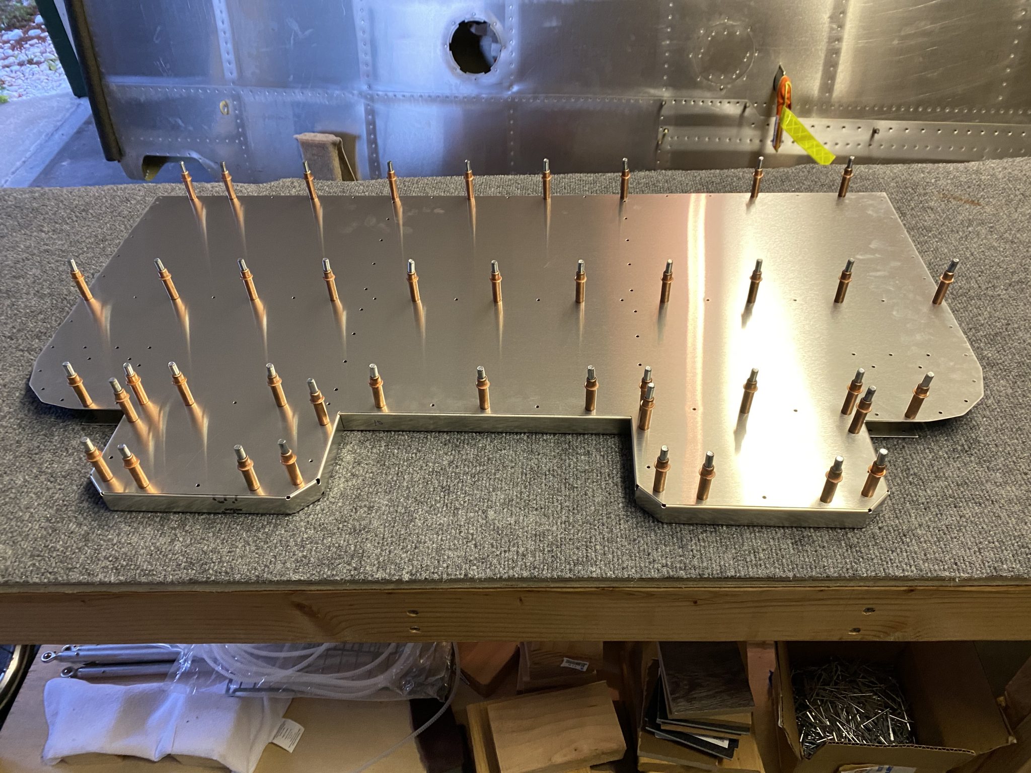
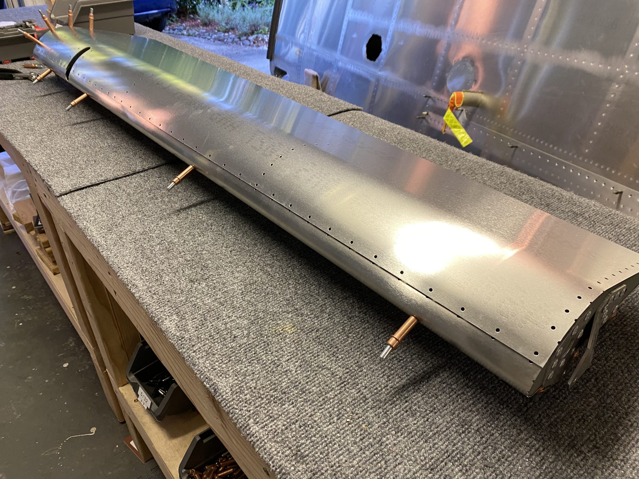
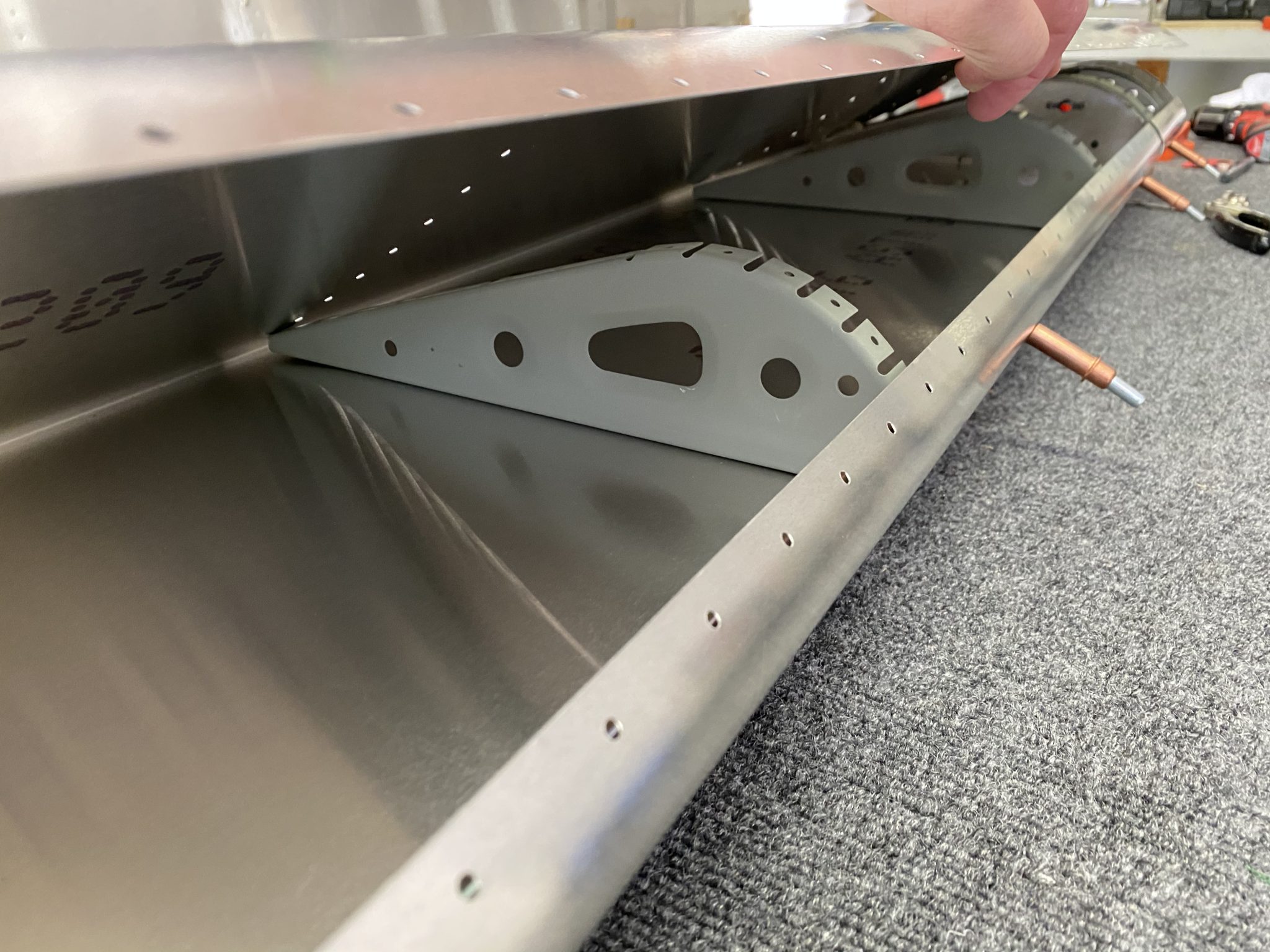
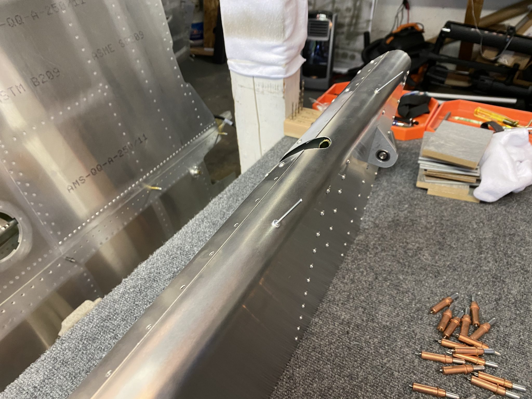
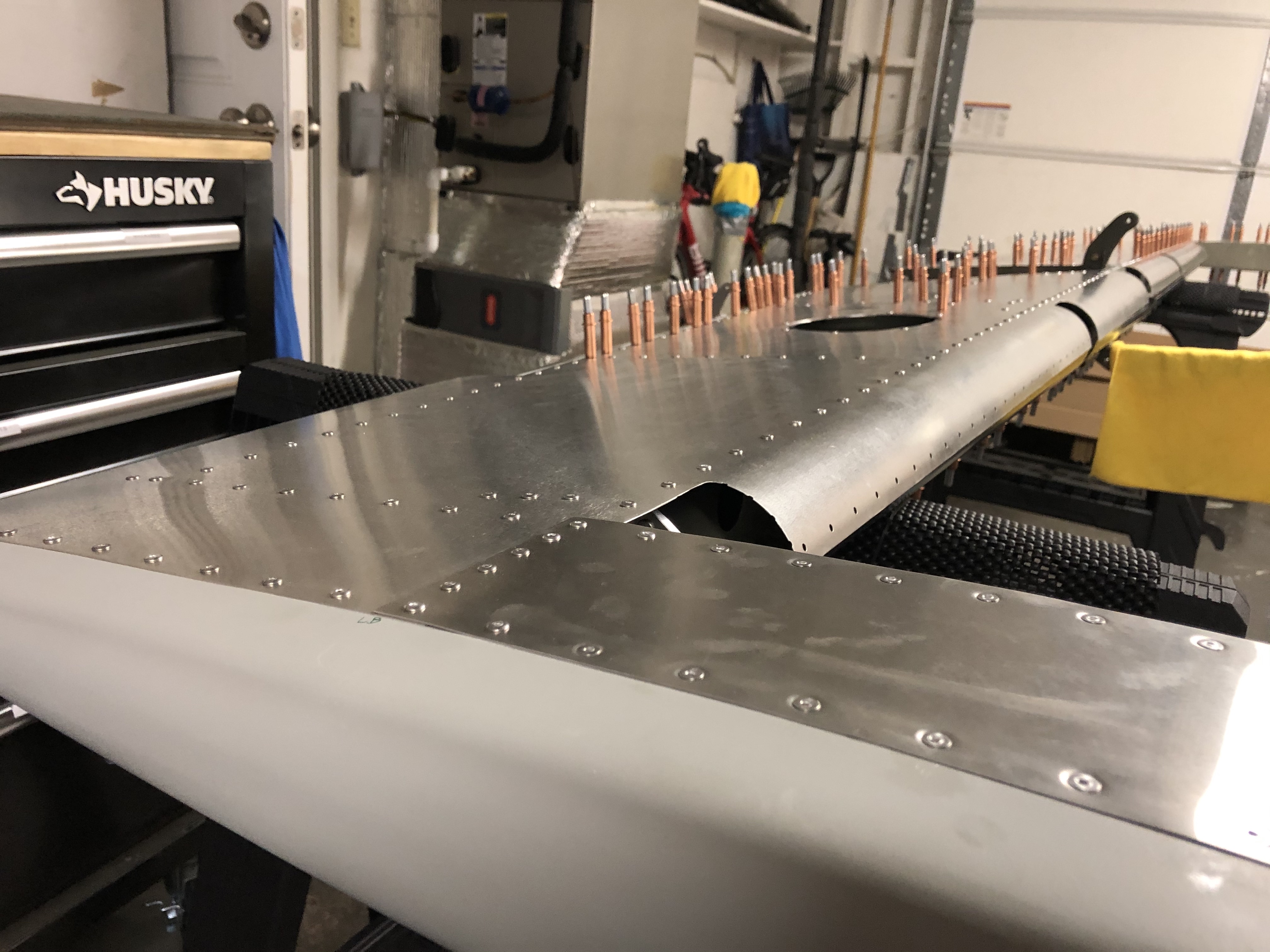
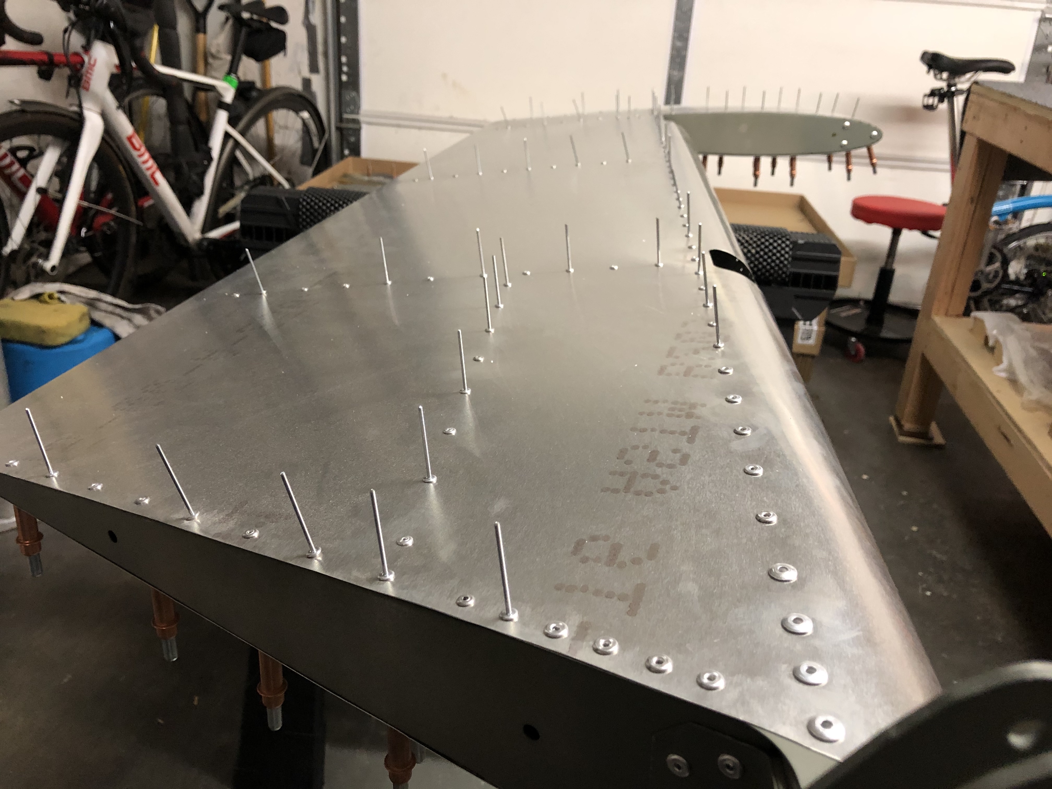
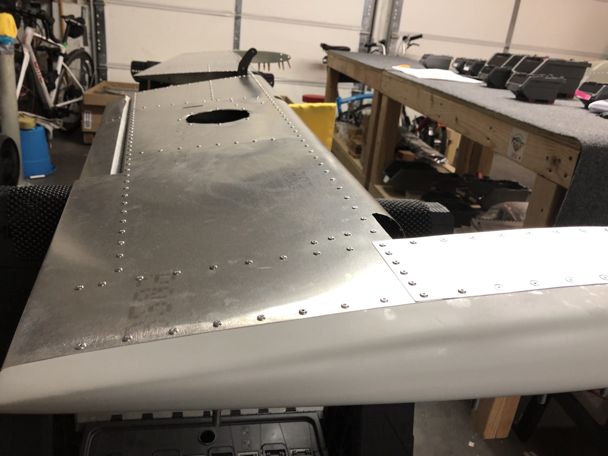
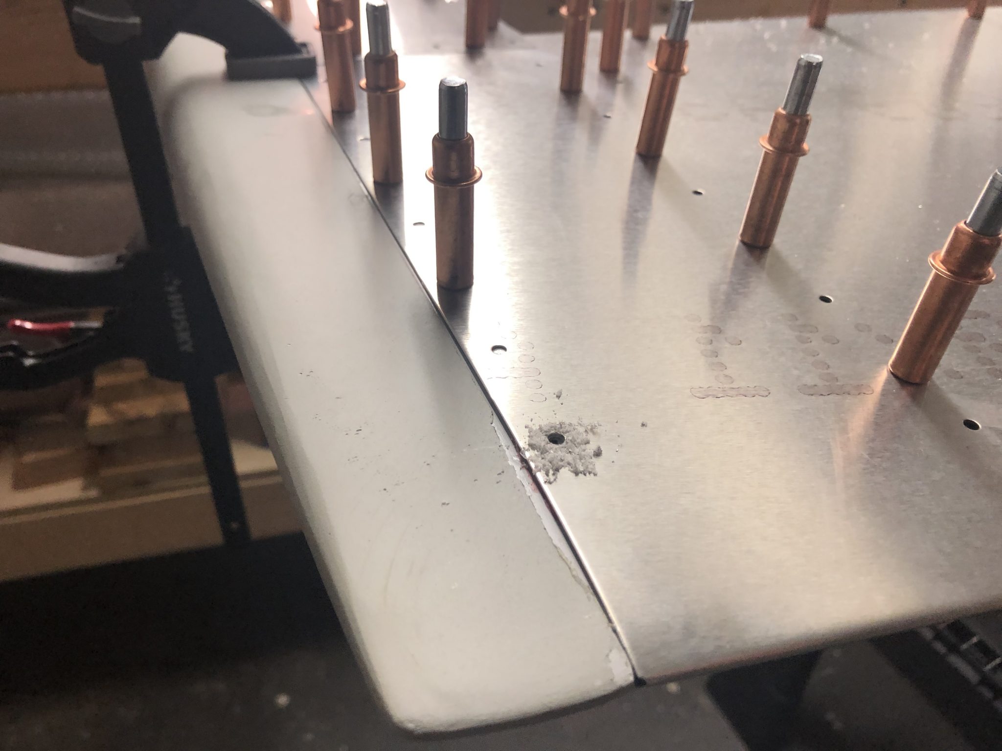
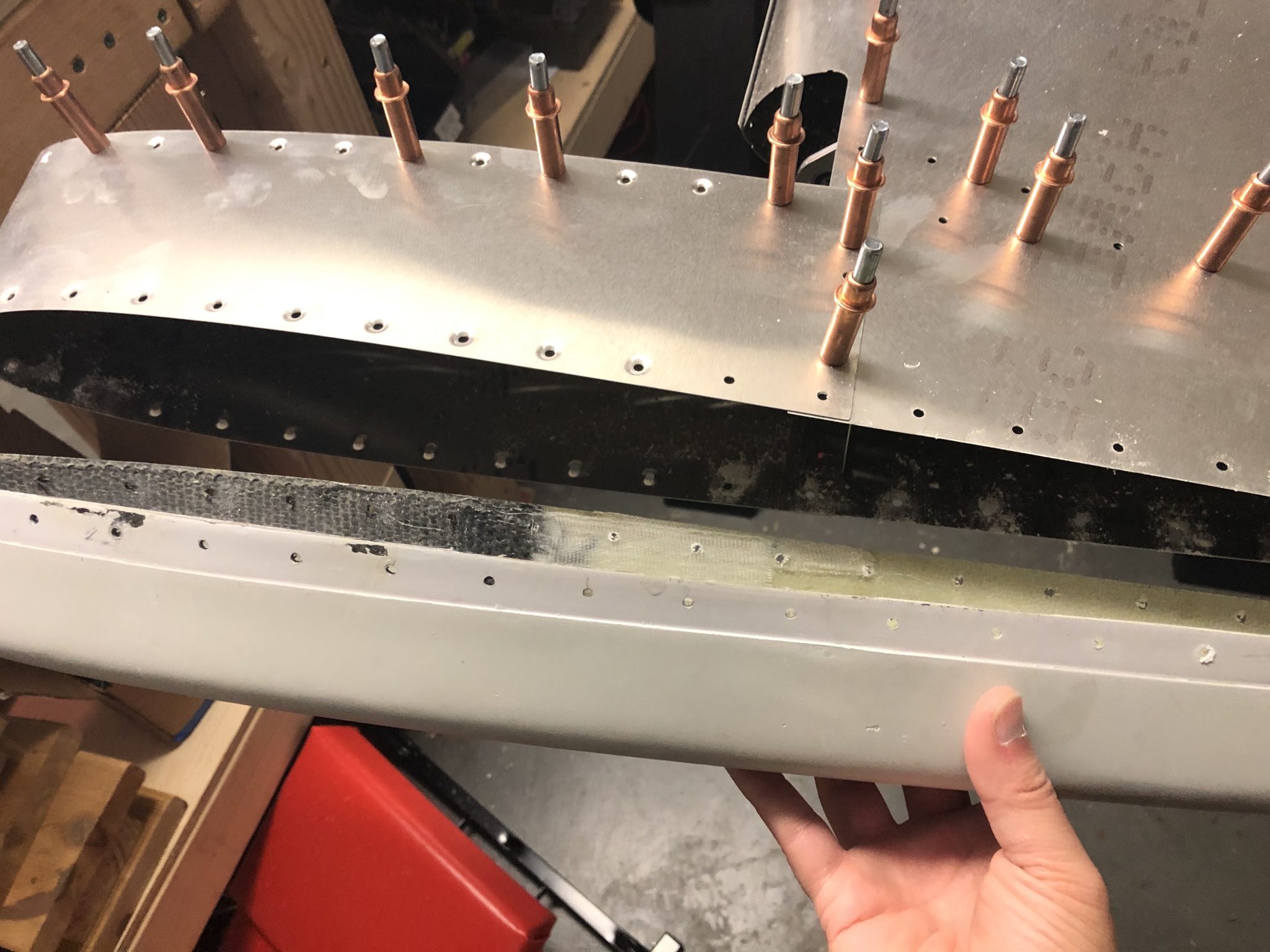
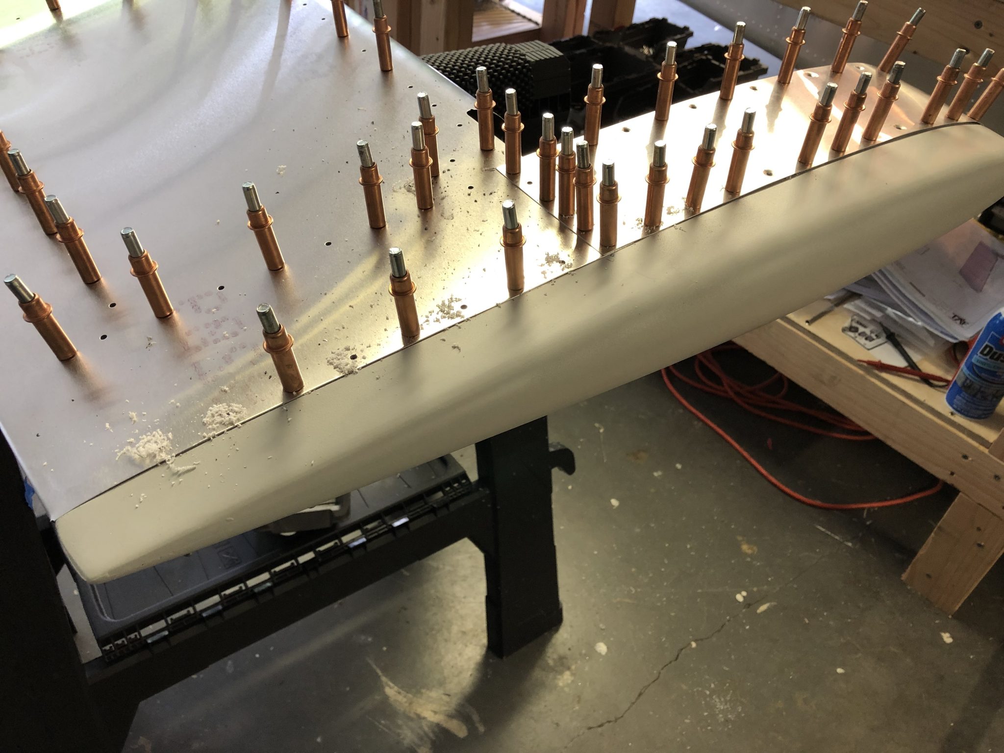
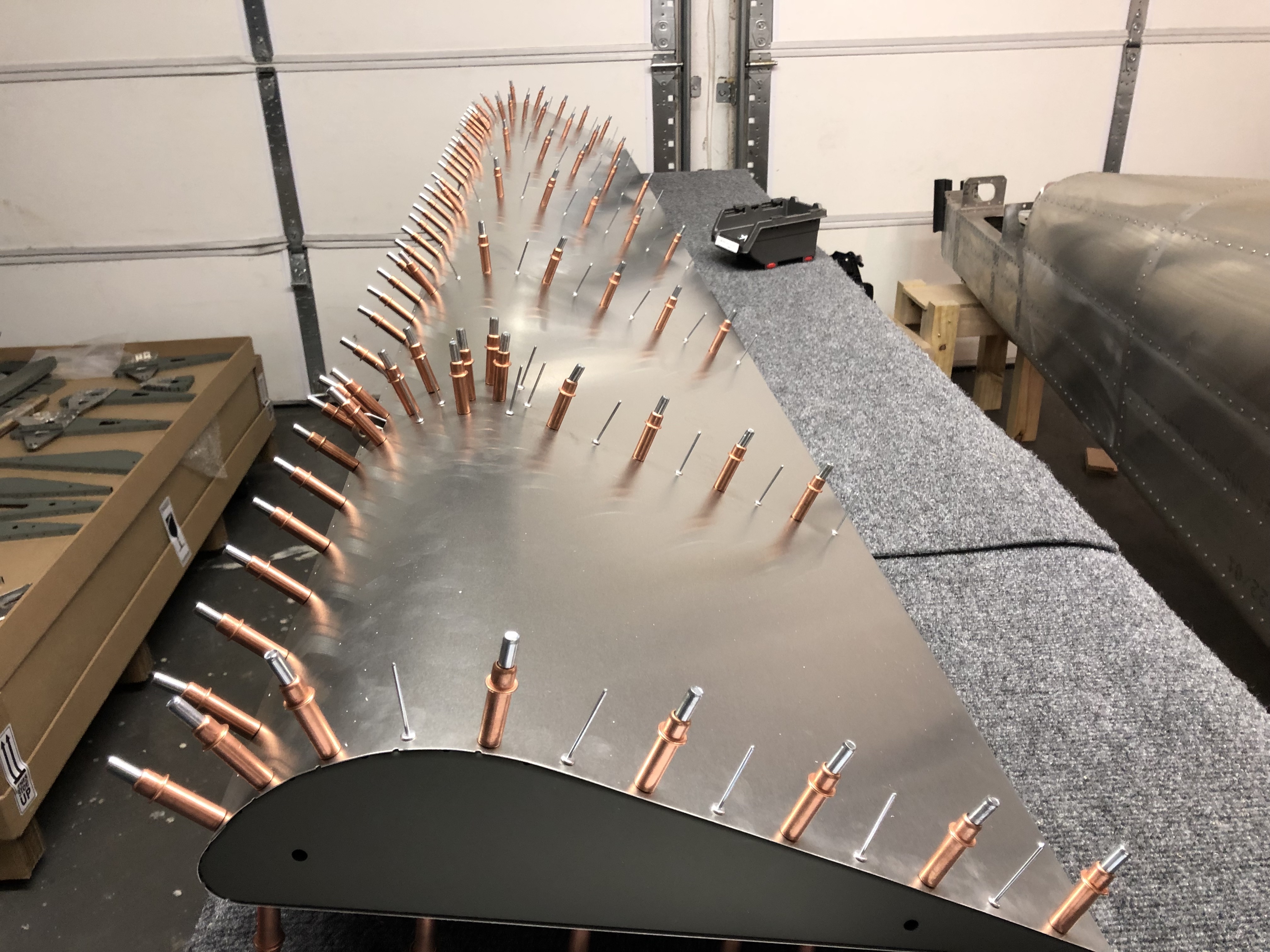
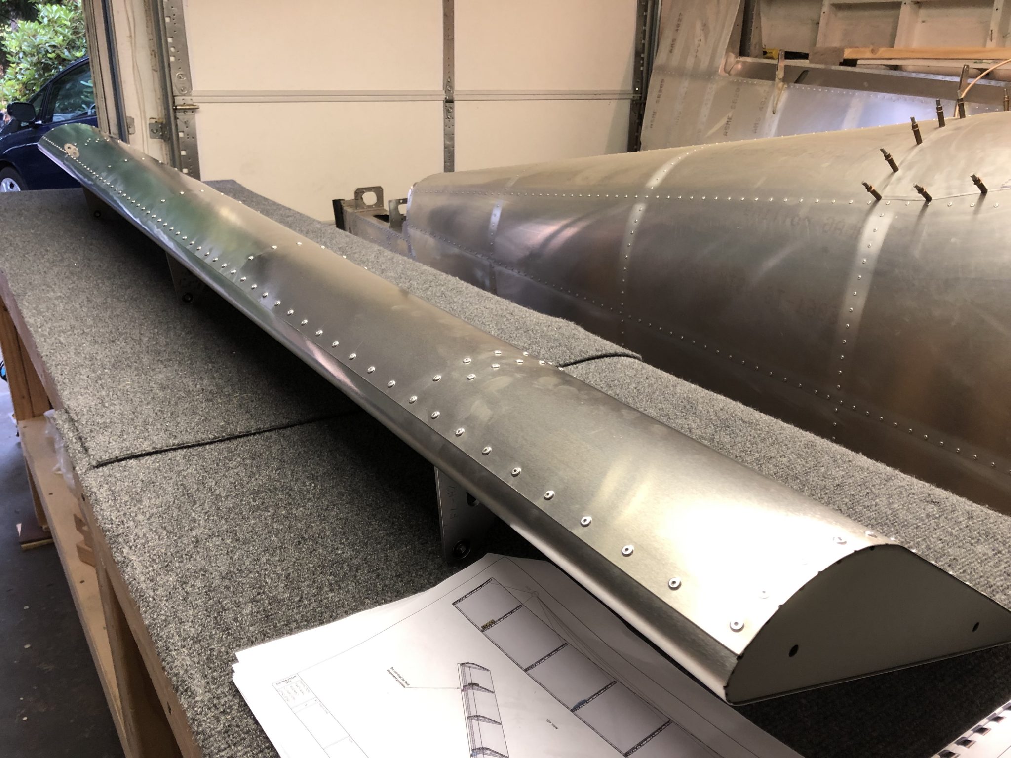
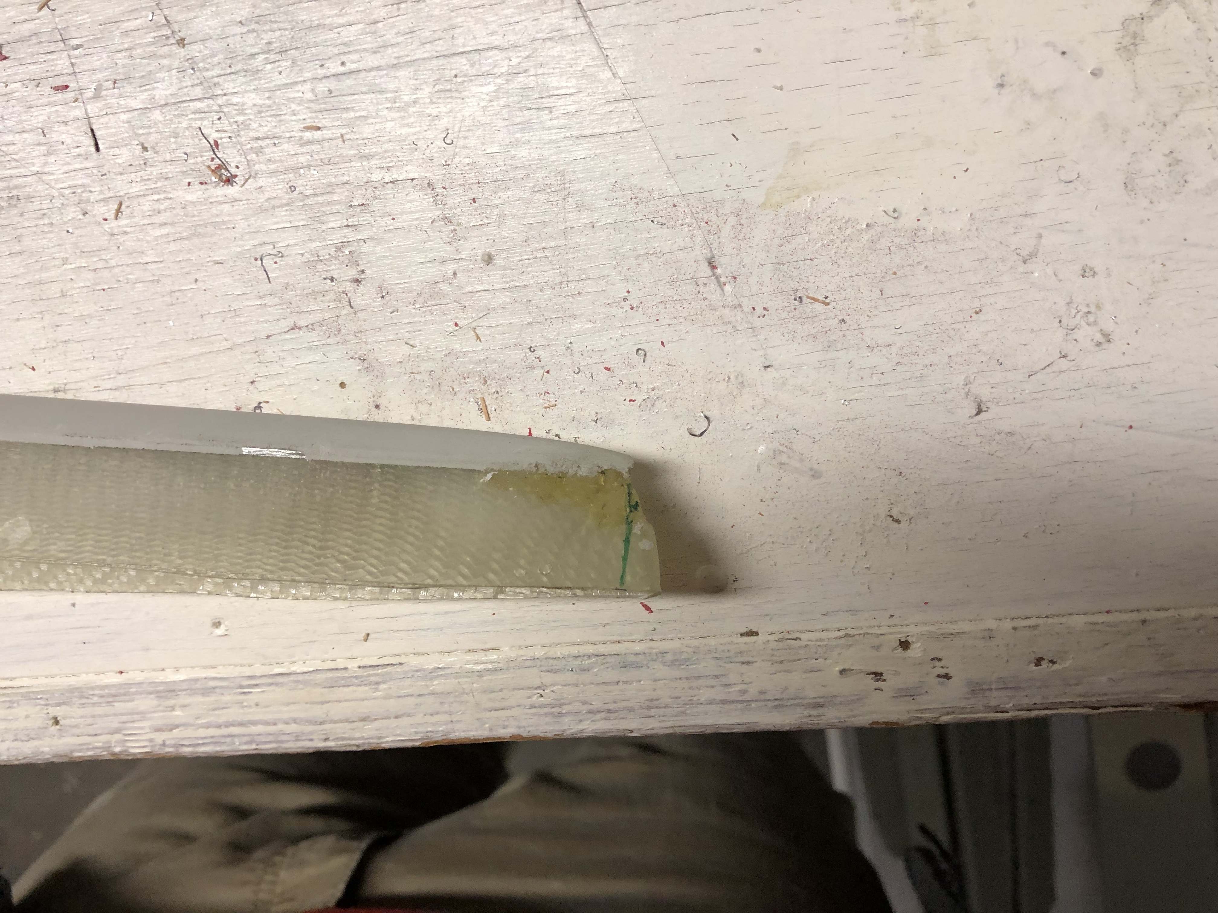
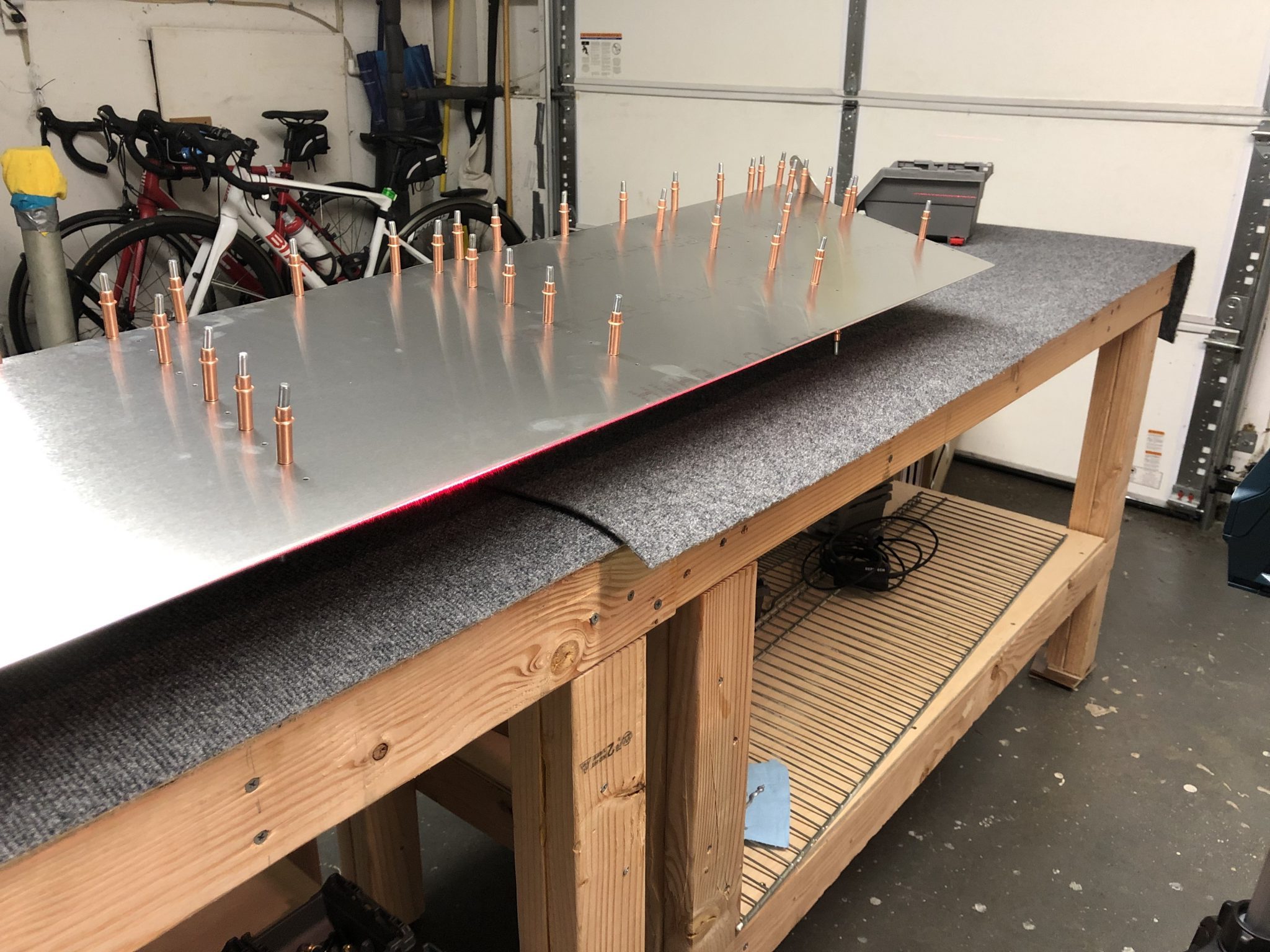
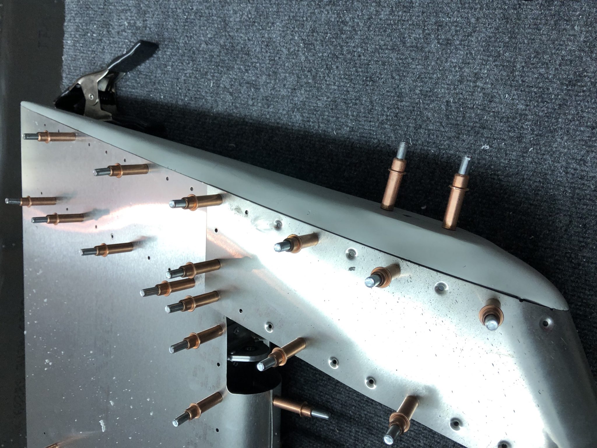
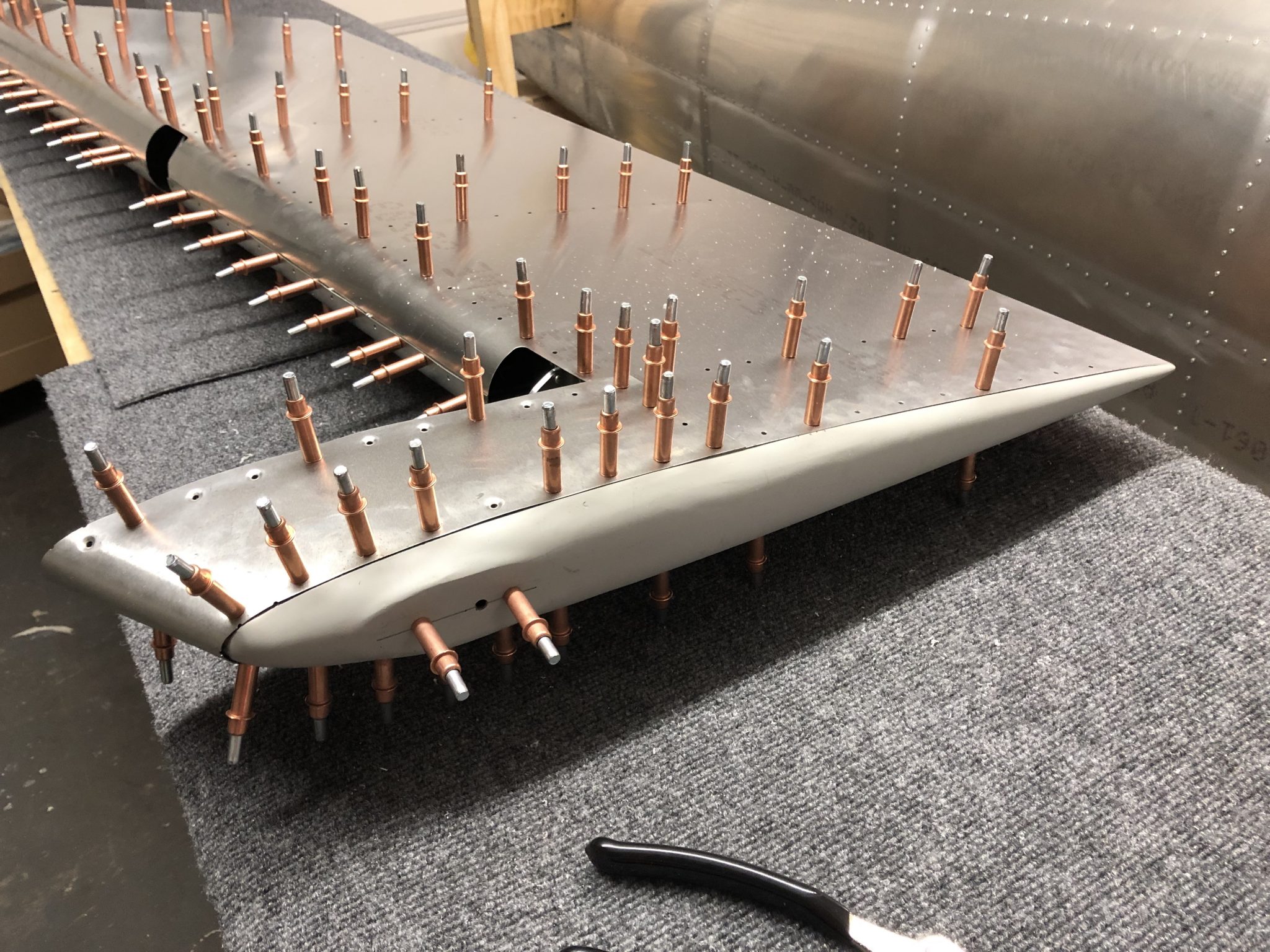
First I clecoed the top skin in place and then I slowly fitted the fiberglass tip in place. In order to get the fiberglass tip to fit, I had to file a tiny bit at the back, but it was much easier than the Rudder tip fitting.

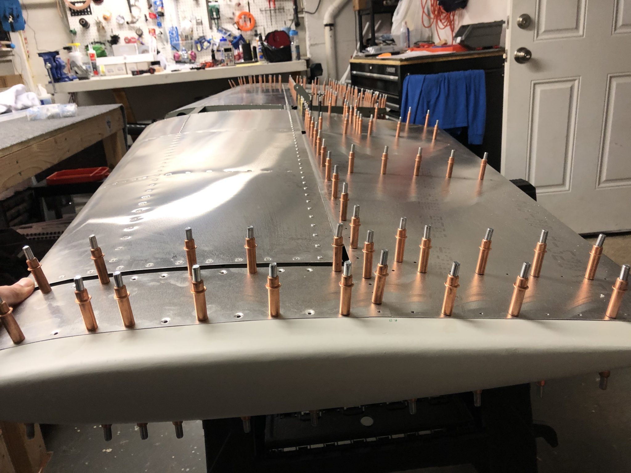
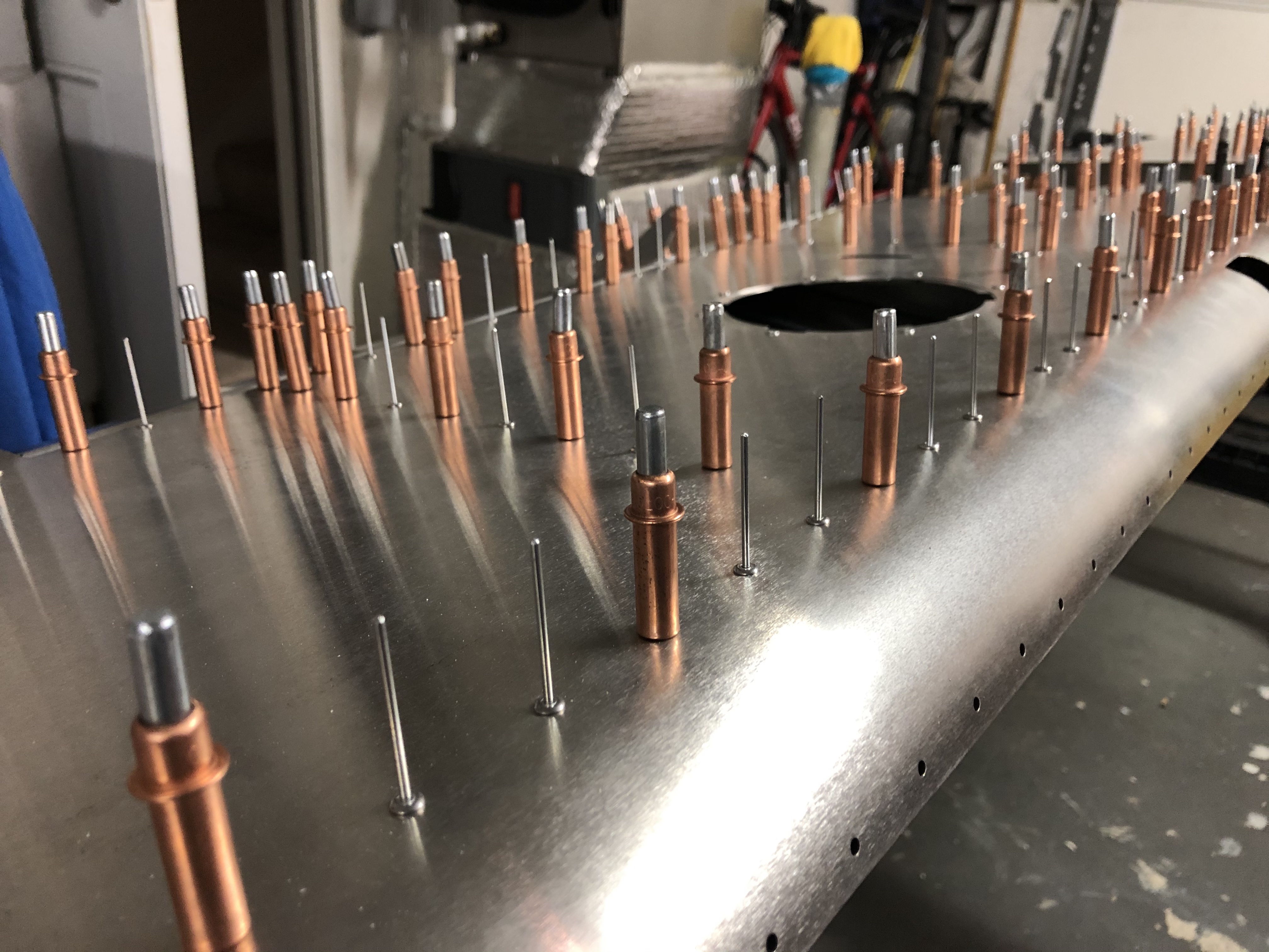
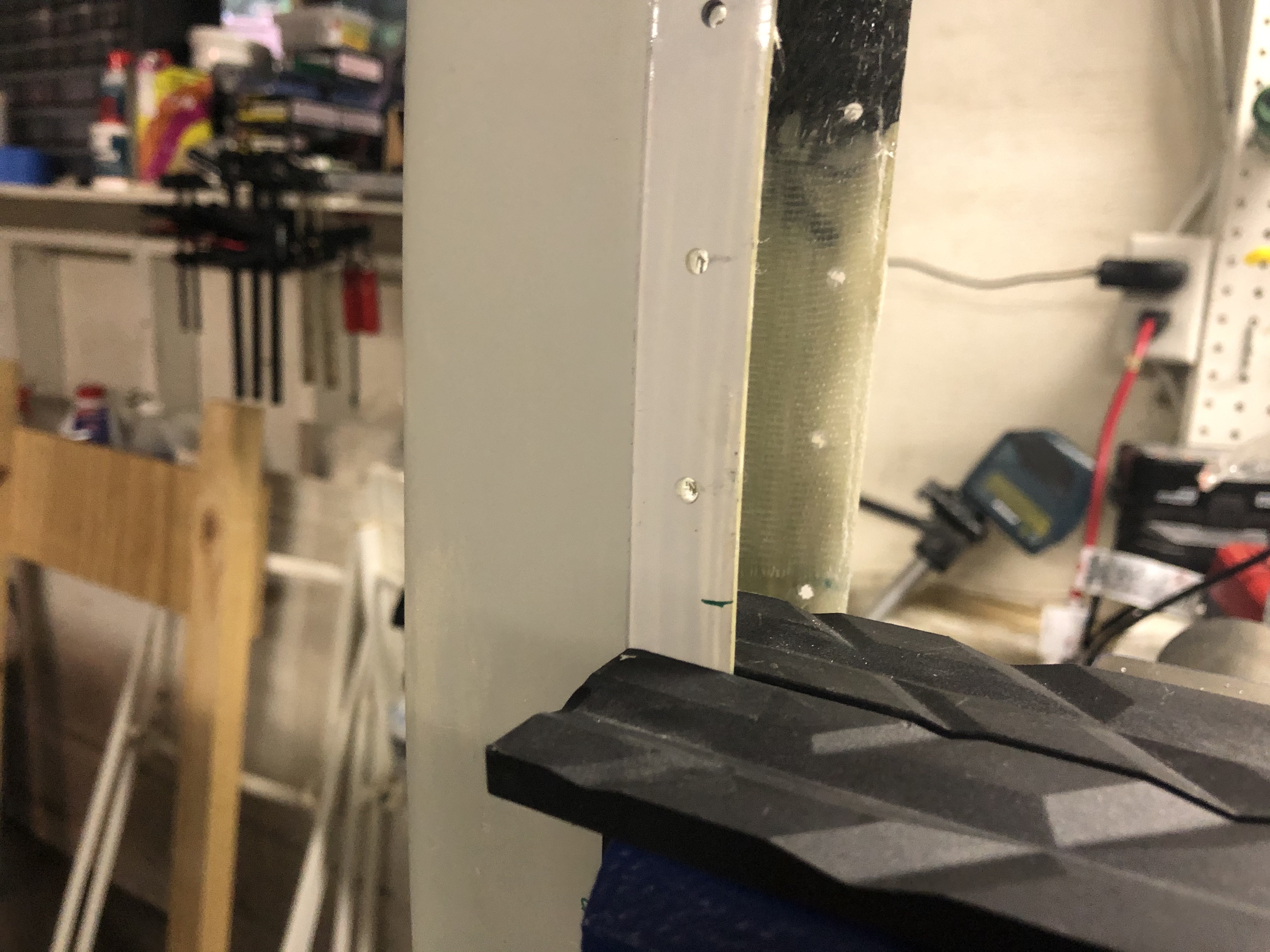
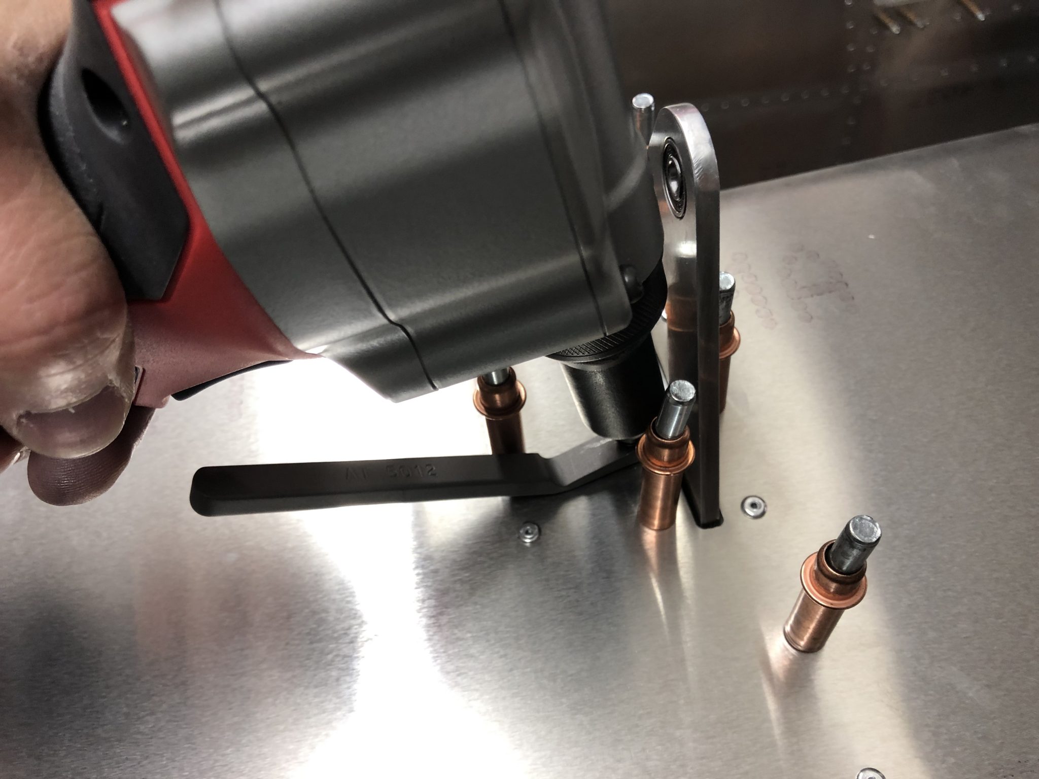
Once I had it in place, I started to hold everything tight together and started match-drilling holes into the fiberglass tip. I used liberal amounts of clecos to get a tight fit and everything looks good. Now I just need to repeat it on the other side.
Top skin clecoed in place Fiberglass tip fit in place and ready to match-drill Marking drill holes Fiberglass tip match-drilled

Finishing the Flaps

Hours: 6

With the ribs for the Flaps out of the way, I am ready to finish the flaps. First order of business is to ensure that I have the ribs all in the right order.
Completed ribs laid out along the right Flap

Once that was figured out, I first clecoed the ribs in place to the bottom of the skins and then closed up the skins and clecoed the top as well.
Ribs clecoed in place to the bottom of the Flaps skin Clecos in place to close up the right Flap

After checking that everything is aligning properly with the skins, I started riveting the skin. The top side is pretty straightforward. For the bottom side, there are a couple of tight spots next to the hinges, so the close quarter rivet wedge came in handy for a couple of the rivets.

Rivets in place Close quarter rivet wedge to rivet the tight space next to the hinge Bottom right side Flap ready to rivet Bottom right side flap almost done riveting

With the right side Flap finished and closed up, I then repeated it all for the left side Flap. There was also a couple of the edges where the hinges sit that needed a bit of deburring attention.
Some deburring was needed for the hole where the hinges go through Upside down view of the left side Flap ribs clecoed in place Almost done with the left side Flap riveting

After I finished the top skins, I did one quick alignment test fit on the wings and everything looked good, so then I finished up both sides by riveting the front rivet lane that closes the skin against the other side.
Front line ready to close up the skins of the Flaps for good Almost done riveting the Flaps Completed left Flap Both Flaps completed

Final alignment check

Once I finished all the riveting, I did one final test fit onto the wings. I used a bit of mason string and my laser level and everything is looking good. Now onto finishing the Elevator.
Final test fitting and alignment checks Final test fitting and alignment checks

Timelapse of building the Flaps

More Elevator priming & assembling center spar structure

Hours: 5

With the weather warming up, I got to spend some time sitting in a bit of sun with the garage door open and preparing, deburring, cleaning and then priming more parts of the Elevator.

Laying out and preparing Elevator parts Primed Elevator parts

Assembling Elevator center spar

The first thing I put together was the Center Spar itself, which I had primed already together with the counterweight the other day. Setting everything up was pretty straight forward as usual and while I was working on it I had a visit from another builder of the EAA chapter I’m part of who actually happens to live very close by and is building an RV. And then another friend was visiting and I happened to have some rivets ready to be riveted, so I continue my new tradition to have guests pull a rivet on the plane and sign it.

Elevator Center Spar Elevator Center Spar riveted

Assembling the center structure to the spar

After the priming from yesterday had some time to dry and set, I went to work to put together the center rib assembly with the center spar. There are a lot of pieces that slot together in there, so it took some time to figure out what slots into which piece. for the center channel to go on:
Center Channel in place

Unfortunately I encountered a problem with the alignment of the holes on the center Rib, both left and right, with the plate as seen below:
Rib holes misaligned with the center plate Closeup of the misalignment of the elevator rib

In trying to figure out which piece is wrong, I started putting together more of the structure temporarily with clecos and the strange thing is that the other holes on the ribs are aligned fine (the black clecos below), so then I thought that it must be the top center plate.

More of the Elevator center structure in place

But then I took off the center plate to check its alignment with the outer skin and there the holes of the top center plate align correctly with the holes on the skin. So this in turn then lead me back to determining that the top (and bottom) holes on the Rib 1 must be the culprit.

It is very strange since the misalignment is pretty severe. It definitely doesn’t look like this could just be resolved by up-drilling the holes, so I sent a note to the factory to ask how to proceed. My guess is going to be that I need new center ribs.


Rudder Tip fitting & riveting the skin

Hours: 2.5

After having primed the inner surface of the Rudder skin the other day, I had all the pieces together to start working on finishing the rudder.

I attached the skin onto the structure and clecoed it into place.Rudder skin clecoed in place

Fitting the fiberglass tip

Once that was done, I went to work to fit the fiberglass tip onto the skin. I had to trim a little bit away from the bottom of the fiberglass. I made a first rough measurement, trimmed it away using my Dremel and then tried to fit it in.
First trim mark on the fiberglass tip

After aligning it all, I did a second small pass to trim a tiny bit more, placed it into the skin again and then it looked all good.
Tip fit in place and held in place using some clamps

Since the instructions are very explicit to make sure that the alignment of the rudder is perfect, I checked the alignment from all sides and it all looked good.
Rudder checked for alignment using laser level Rear of the rudder checked for alignment using laser level

After all that looked good and triple and quadrupple checking that the fiberglass tip sat flush in the skin I made marks for match drilling the holes and then went to work and carefully drilled the holes into the fiberglass.
First few holed drilled into the fiberglass tip Finished drilling all the holes in the fiberglass tip

Countersinking the front of the fiberglass tip

Once that was done, it was time to countersink the holes in the front. The instructions contradict themselves – only the first 7 holes get countersunk rivets, which mathematically adds up properly to the 32 rivets (2 x 7 on the top and 2 x 9 on the bottom = 32). So after counting all the holes and re-checking the instructions and doing basic math, I decided to only countersink the first 7 holes. I sent an email to the factory yesterday and they confirmed that I was right and they’ll fix the instructions in the next iteration.
Instruction error about countersinking

Before I went to work with the countersinking, I calibrated the micro stop countersinking tool using a scap piece of Aluminum to ensure the depth was set correctly and made sure that I had the correct 120 degree pilot cutter in the tool (I made a whole post about why using the 120 degree pilot was important here).
Calibrating the Microstop Countersinking tool Making a test countersink on a scrap piece of metal

After all that was ready, I went to work, mounted the fiberglass tip gently in my bench vise and started drilling the countersink holes.
First countersunk hole drilled Checking depth using a countersunk rivetAll the countersunk holes drilled in the fiberglass tip

All the countersunk holes came out well and everything sits flush now.
Flush fit of the fiberglass tip in the Rudder

Riveting the skin

So after all that I went to work and started riveting some of the skin.Time to rivet the Rudder skin The close quarter wedge came in handy for riveting in this tight spaceRiveted part of the Rudder skin