I had an email conversation with a new future Sling TSi builder over the past two days. While he is waiting for the kit to arrive, there is the hard question of “how to get started”. This question comes up for every new builder, and those that haven’t made up their mind yet, but need some guidance on what it would take to actually get started.
I remember from my own journey of when I got started, that the sheer amount of information out there can be overwhelming and finding some kind of guide-posts can be helpful to make a start.
So I’ve written up a page on my blog on how to get started, from considerations about the workshop, to a few books I found helpful and the large list of tools you’ll need.
I hope this will be helpful to future builders and those evaluating their options.
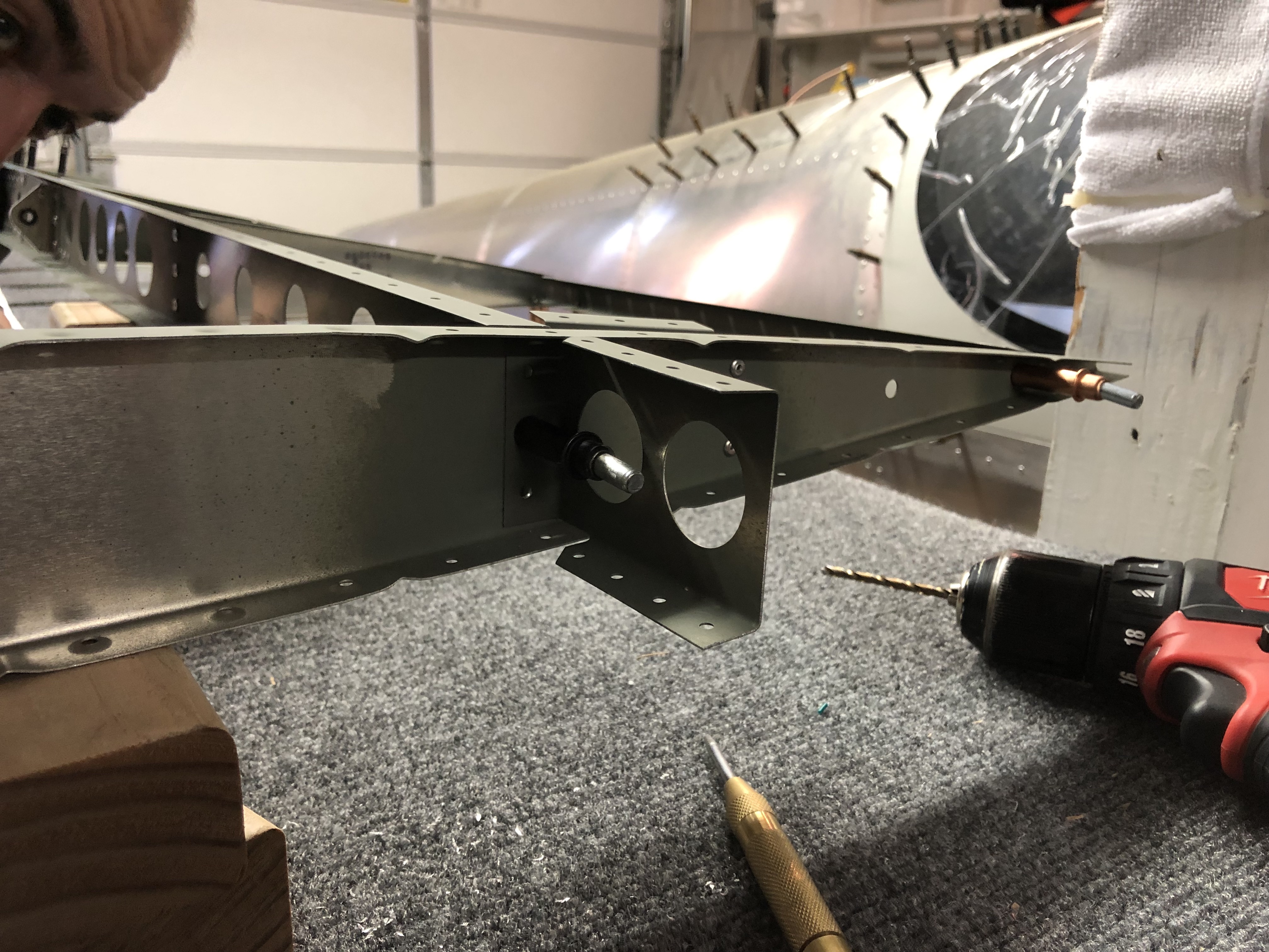
One of the things that the factory forgot as part of the change from the Sling 4 to the Sling TSi was the required access to the internals of the wing next to the Pitot tube.
In the Sling TSi design, some inspection panels were removed including the one next to the Pitot tube. By itself, if someone was building the wings from scratch, that might be fine as long as the builder installs the Pitot tube beforehand and doesn’t anticipate to ever need to access it, such as if using an unheated Pitot tube.
However, I am going to use the Garmin heated & regulated Pitot tube, which not only requires wires to be run to the Pitot tube, but also that I need to mount the regulator unit next to it.
Since I ordered the quickbuild, I ordered it with this specification, but unfortunately the factory didn’t receive the Pitot tube from their supplier in time and shipped my kit without installing it.
So after I received my shipment and inspected everything, I realized that installing this after the fact wasn’t going to be easy, particularly with the lack of a hole in the wing. Unfortunately the factory also forgot to run the wiring to the pitot tube, which creates a whole second issue, for which I’ve been working on a solution.
I informed the factory a while ago and also gave Matthew, one of the other TSi builders a heads-up since he hadn’t started on the wings yet. The factory realized their mistake in the plans and promised to come up with a solution and send me instructions and a plan.
Drafting a plan
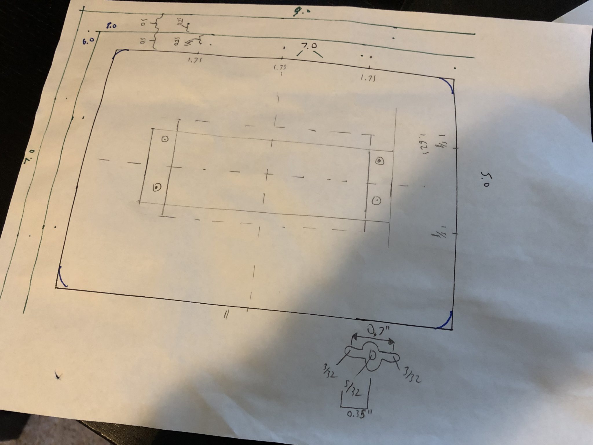
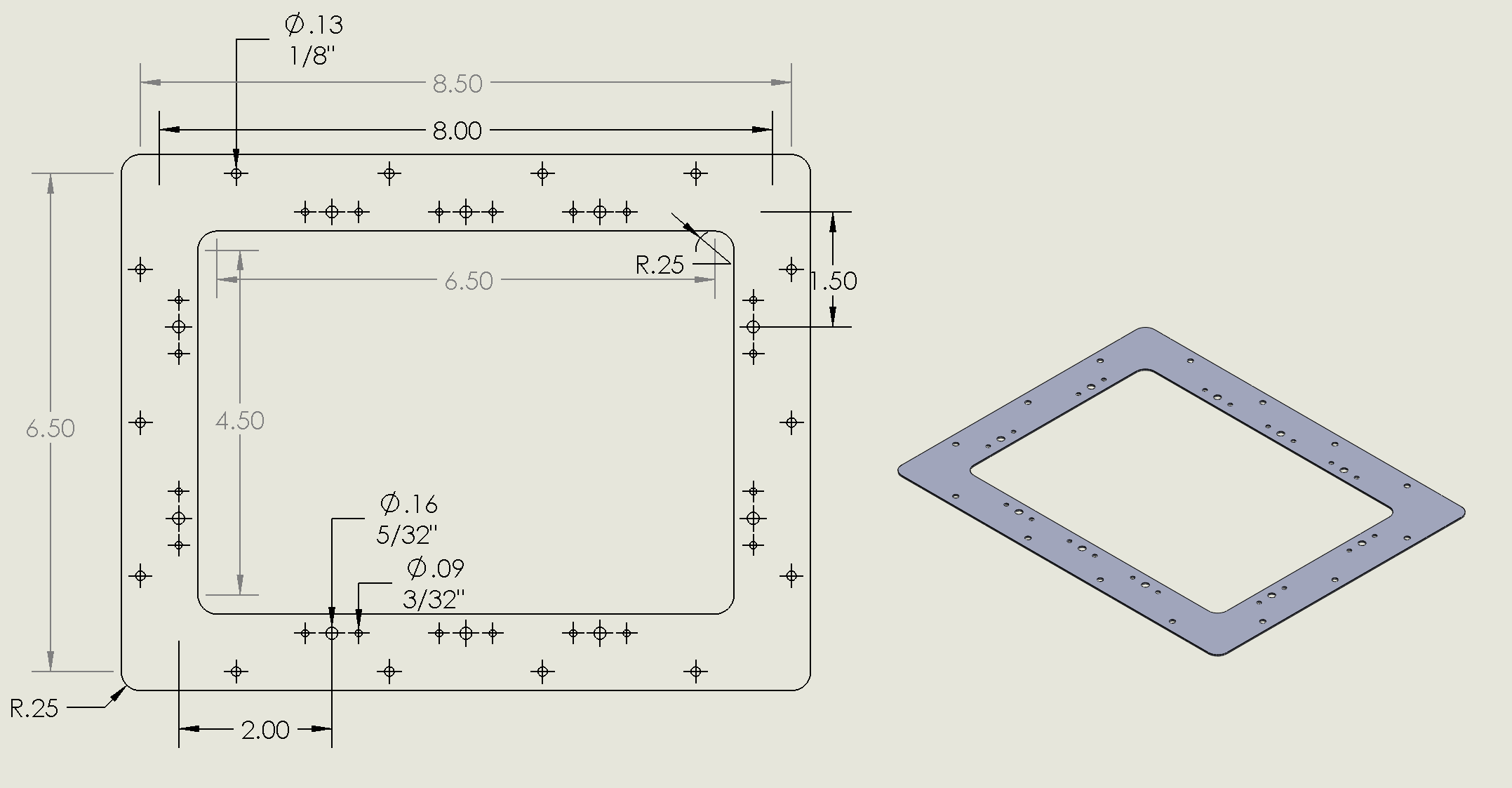
While I was waiting for the factory to come up with a plan, I actually started drawing up my own plans to fabricate the entire inspection panel myself and used it as an opportunity to learn and use Solidworks, which I can use for free as part of being an EAA member.
Since I had the chance to chat with Mike Blyth at Oshkosh for a while and we chatted about my build, I mentioned that I was still waiting for the factory to come up with a plan for the inspection cover and he promised that he’d check on the progress when he got back to South Africa and indeed, two weeks later, I got an email with the plans.
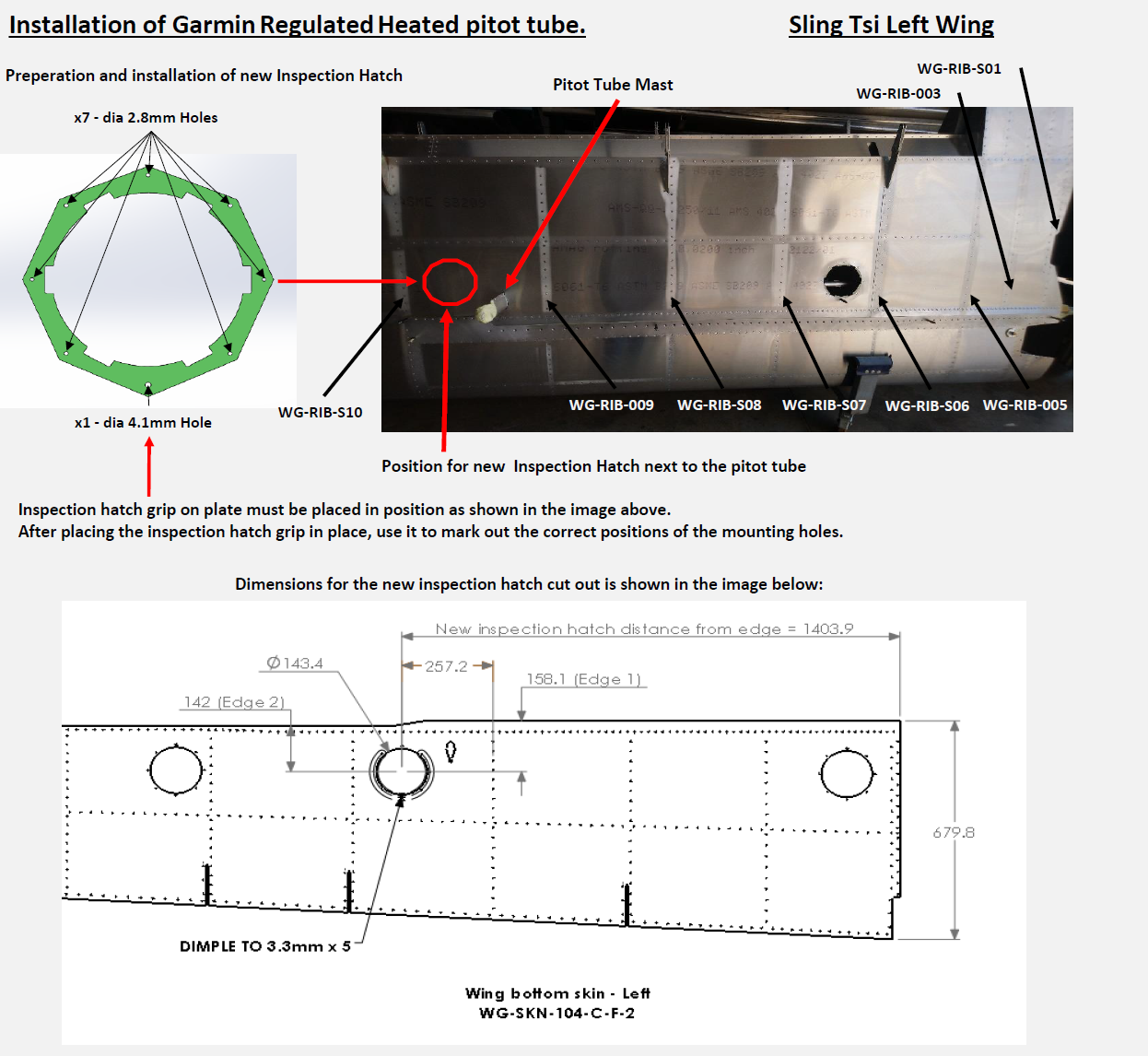
The factory plans, in keeping with the other inspection access panels, uses the same flush round inspection cover that is used to access the Flaps and Aileron connecting rods.
Since I am still busy with other things in the build and haven’t actually made my own panel yet, I am going to go with the factory plans that they have drawn up for me.
Cutting a round inspection access panel hole
There is just one difficulty to overcome – the access panel is round and large and I don’t think there are 143.4 mm drill bits I can buy in Home depot.
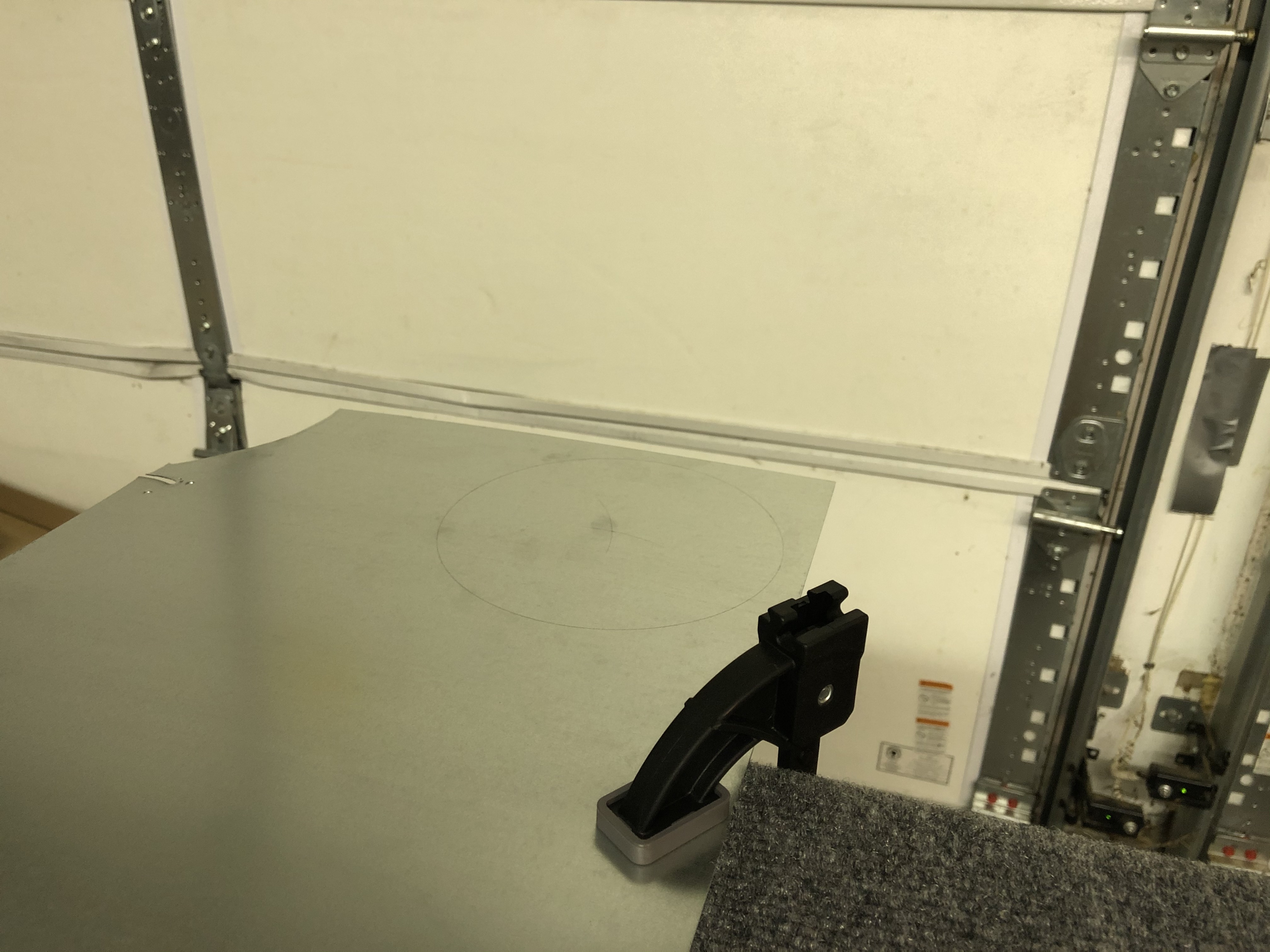
Since this is quite an operation, I decided to get some practice with the tool on a piece of spare aluminum and also made a video of it, since I figured that it might be helpful for other builders in the future.
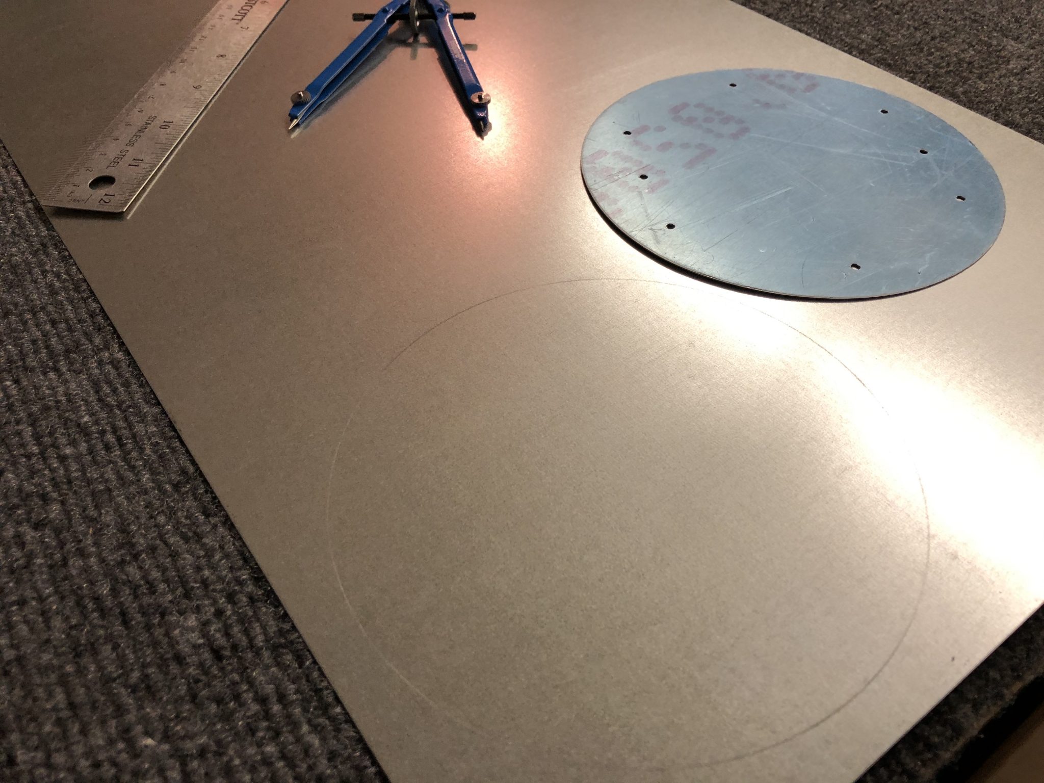
I started by marking out the circle using a drafting compass. It’s been quite a few years, but luckily I still remembered how to use it and how to find the center of the circle again by making two marks. Proof that you may indeed use what you’ve learned in geometry class sometime in life, even if it’s 15 years later. After that I clamped the piece of metal on the edge of the table.
I drilled the center pivot hole to 1/8th of an inch, which makes the pivot sit in the hole and then measured out the starting hole for the drill, make a starter hole and then used a step drill bit to upsize the hole until it aligned with my marked circle.
After that, I set up the drilling tool with the pivot and made sure that the outside of the cutting bit aligns with my circle and then attached the drill and went to work.
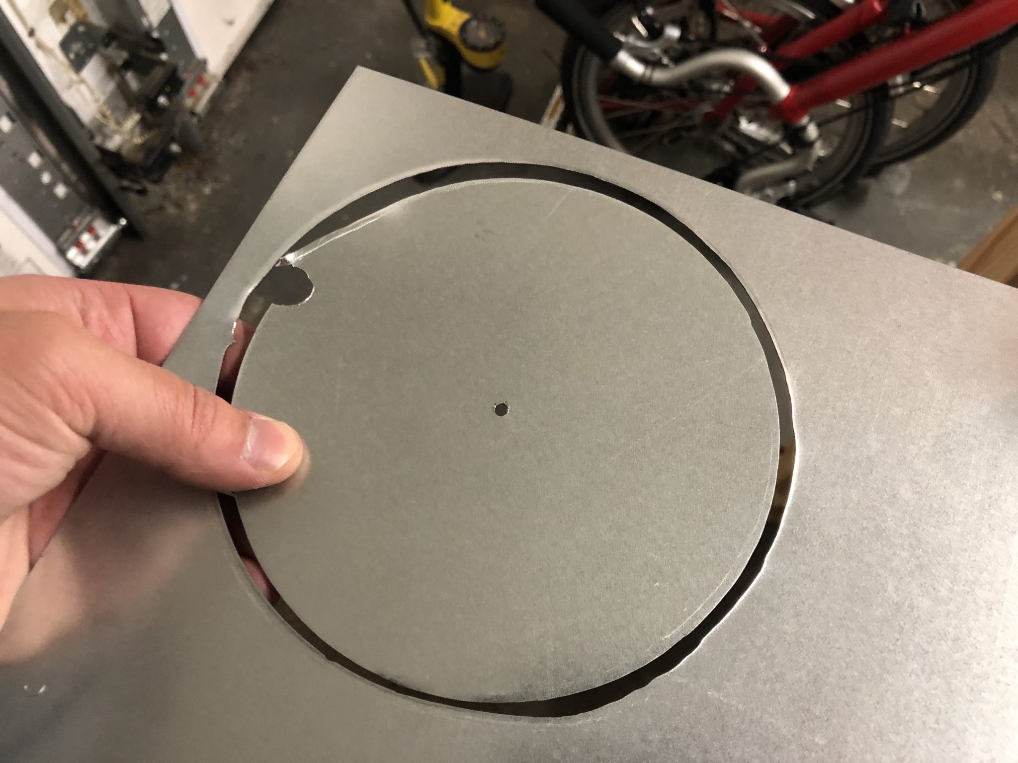
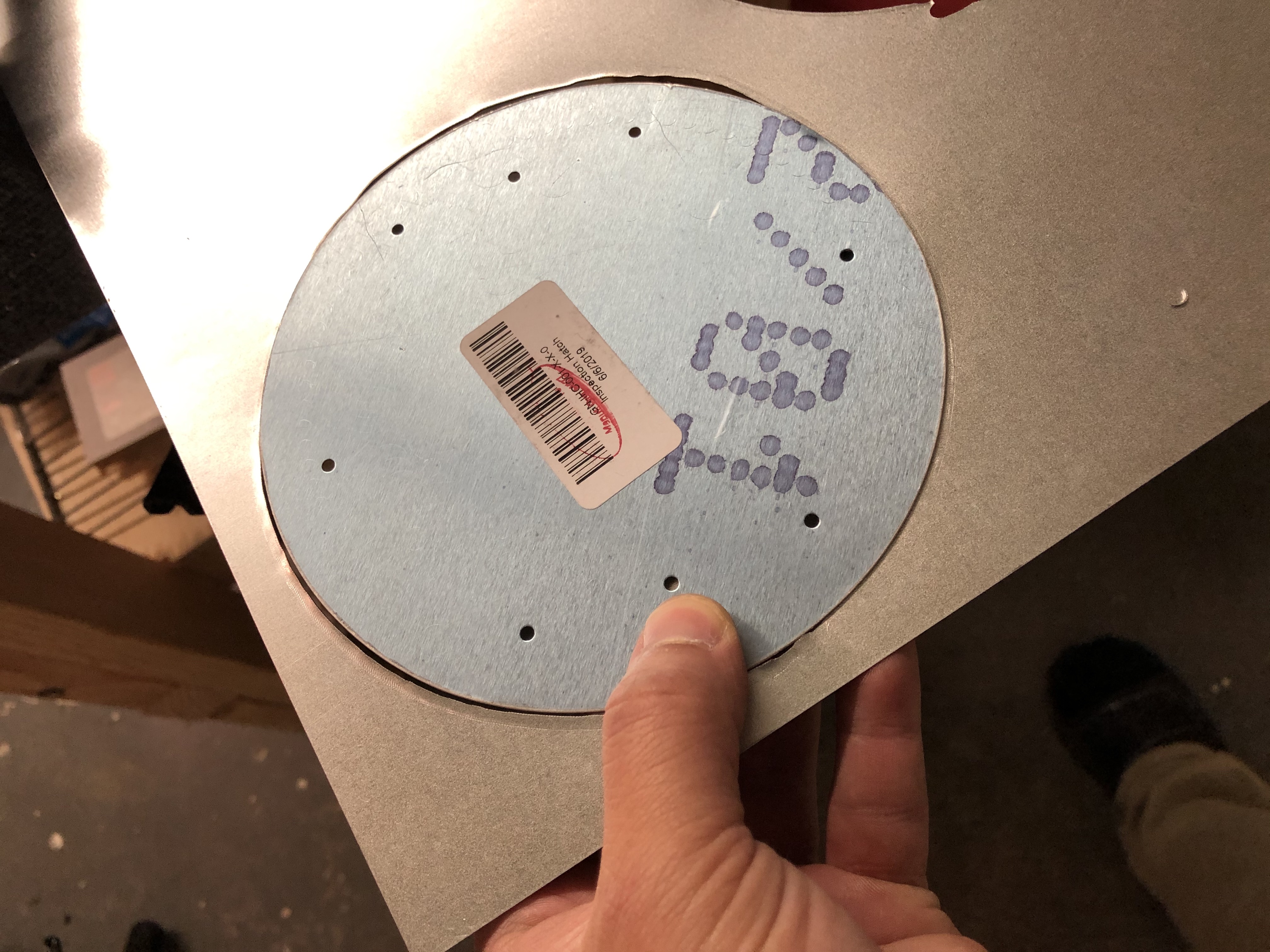
Here are a couple of pictures of the first circle I cut – note that briefly I had the pivot point jump out of the hole, which caused me to waver a bit which you can see towards the bottom where it’s not perfectly round, so make sure the pivot continues to stay in the hole.
Annotated video of the process of cutting the hole
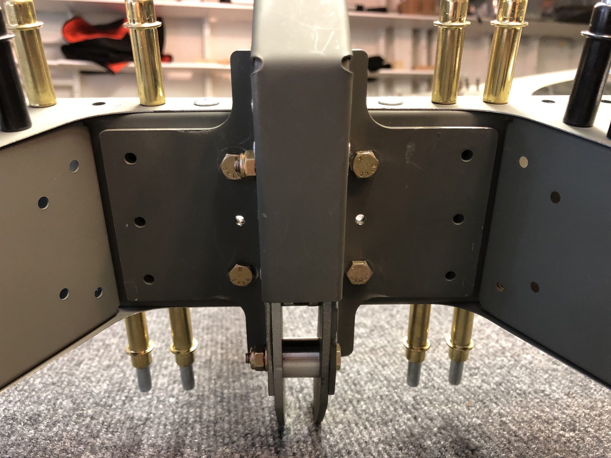
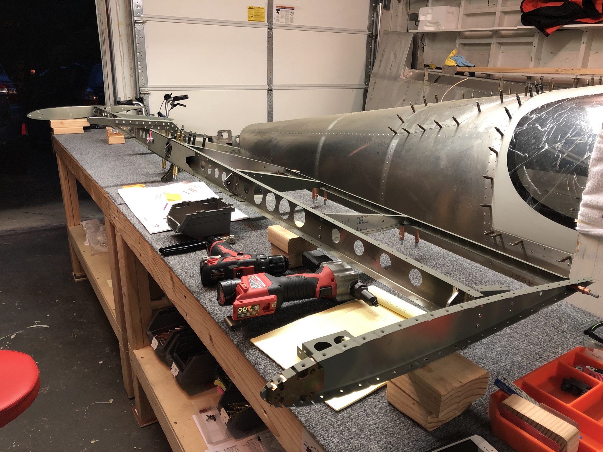
Time to finish off the Empennage and get the Elevator structure going. I received the replacement ribs that are bent just that little bit more in order to properly align with the reinforcement plates and skins and went to work to drill out the bad ribs and put in the replacements.
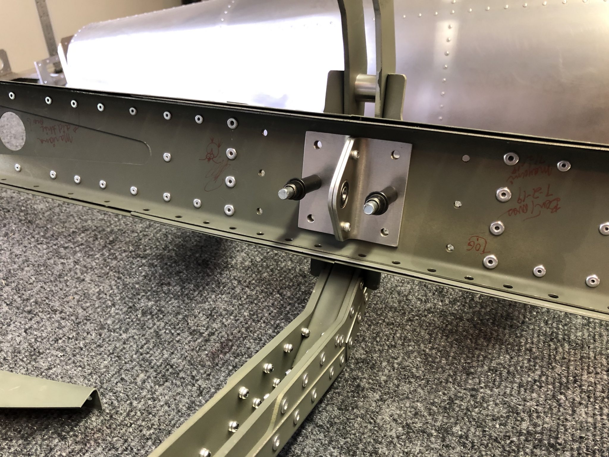
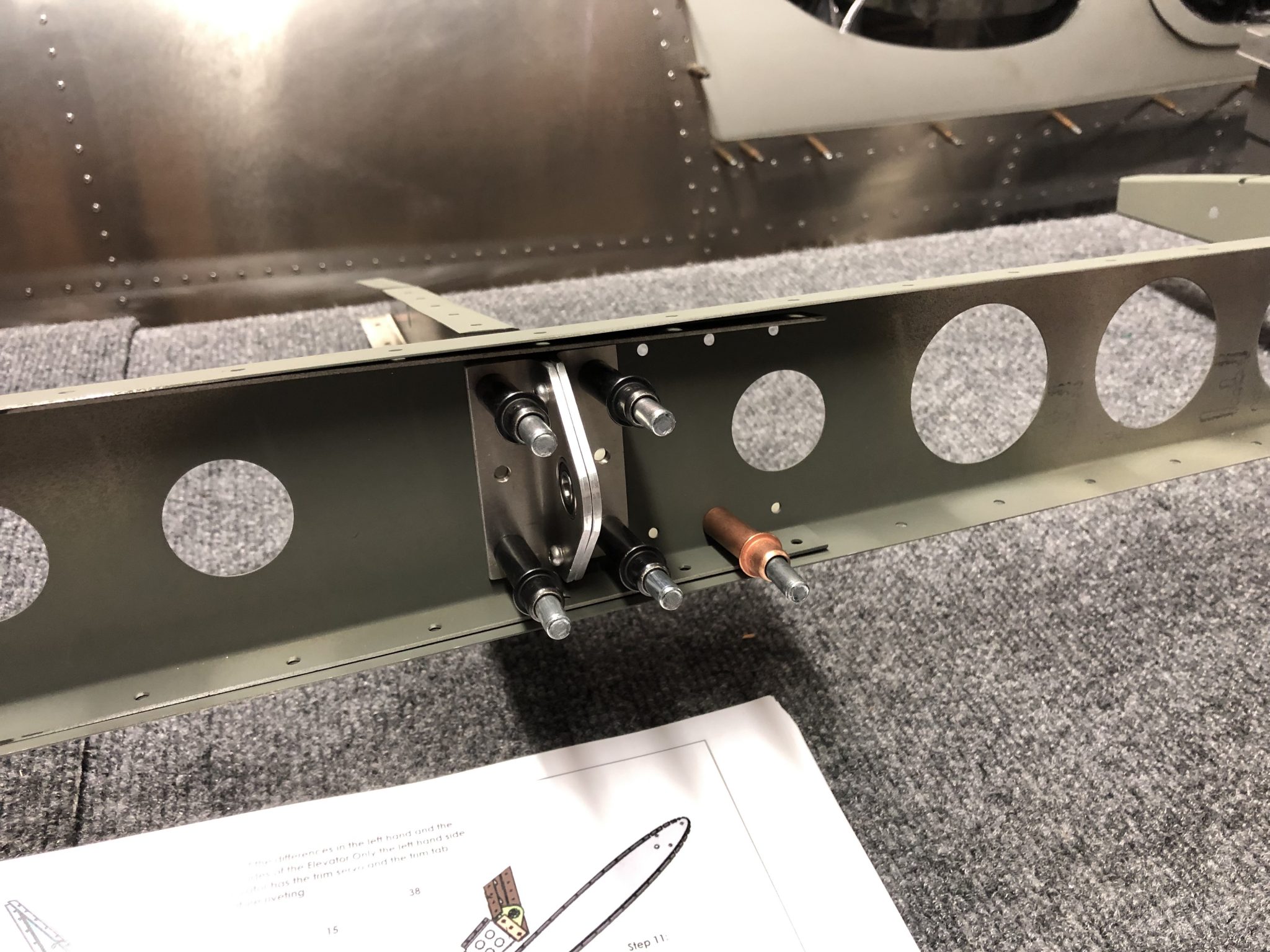
After that, I went to work and torqued the bolts that connect the control rod and counterweight to the Elevator. There’s also a small support bracket that reinforces the center rib to spar attachment, which is a pretty tight fit, so I had to get out the manual hand riveter.
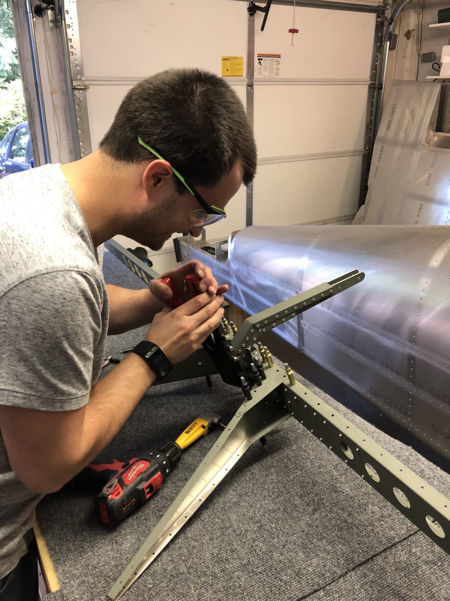
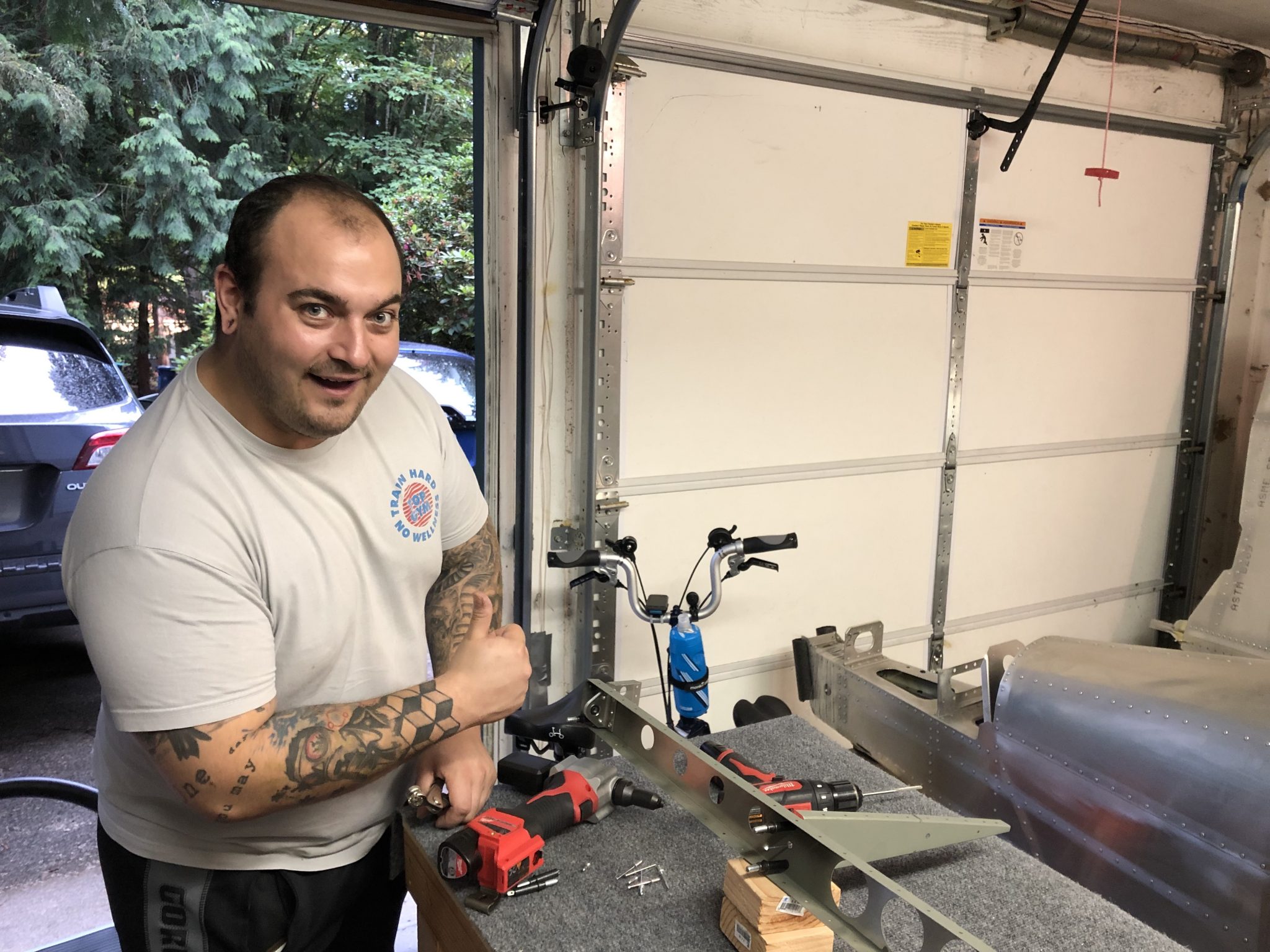
My brother is currently visiting and is enjoying the riveting experience.
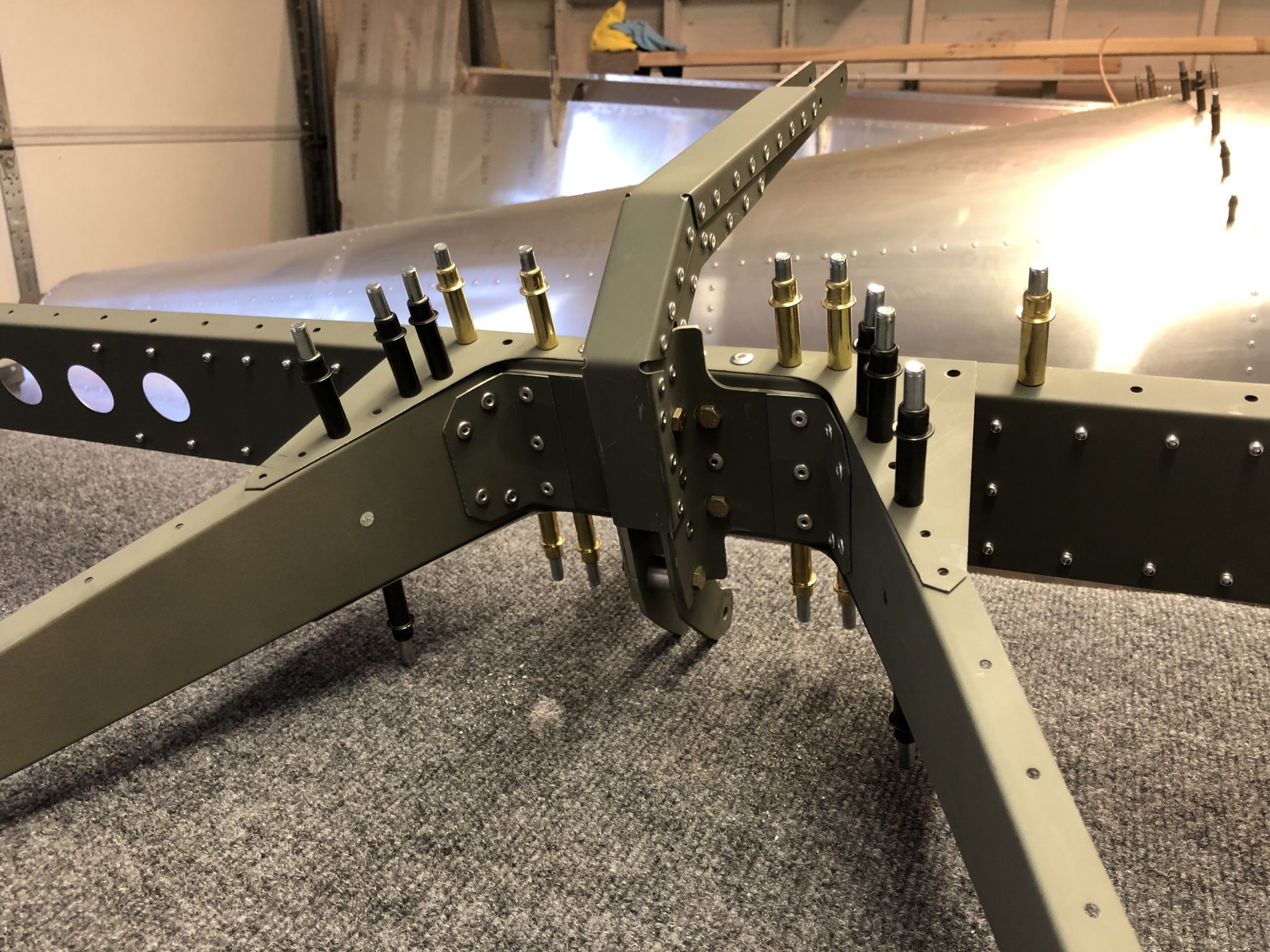
Once the center ribs were finished, we moved on to put the rest of the rib structure in place.
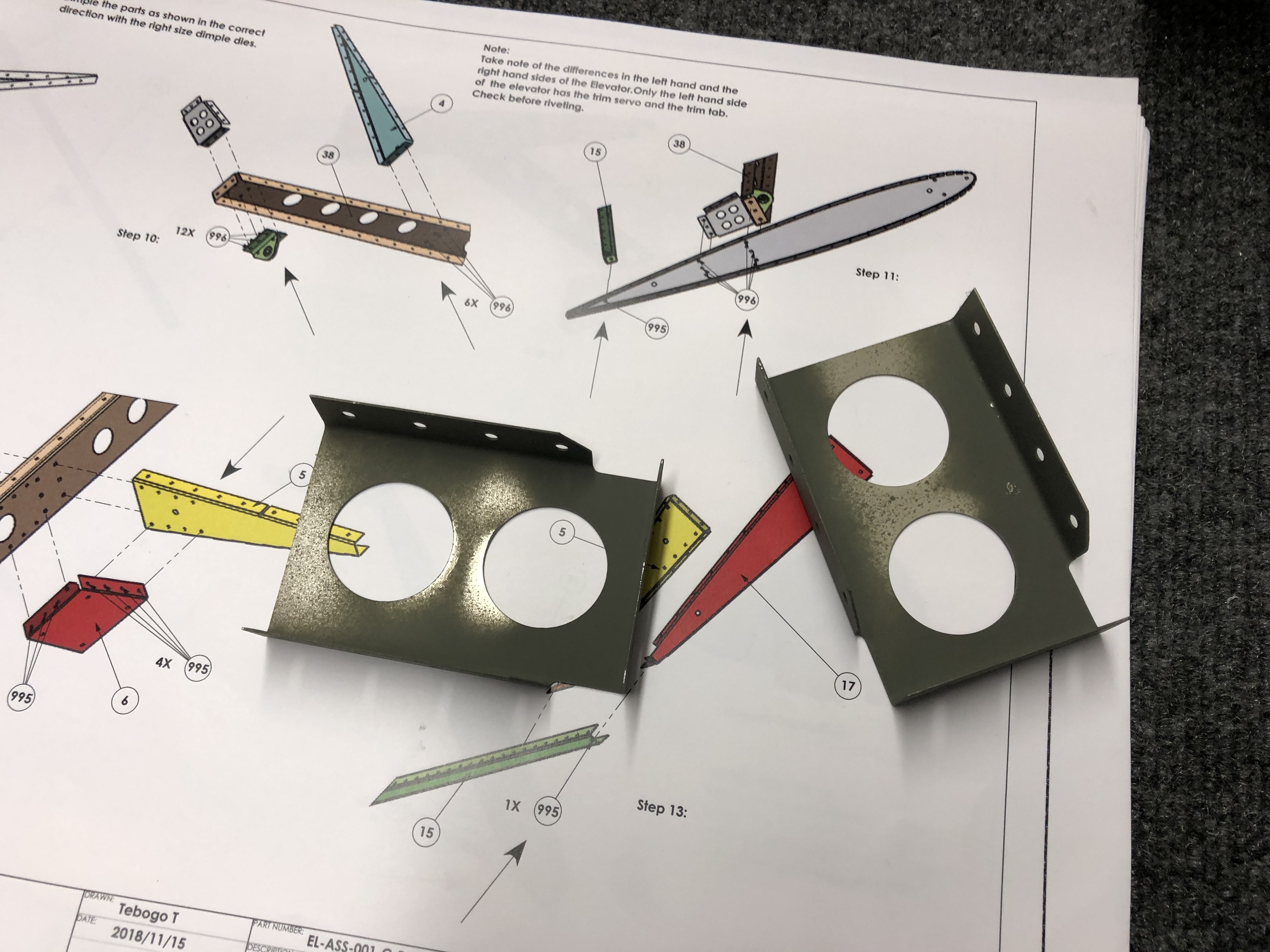
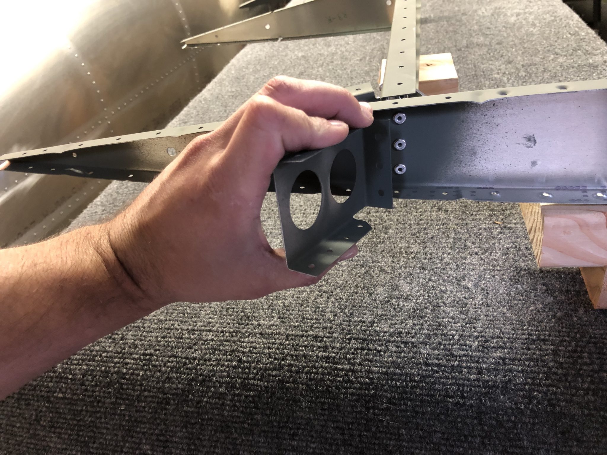
After that I realized there’s a mistake in the plans as they instruct to rivet the edges that hold some of the side counterweights on, but there’s another small end rib that actually has to go on there as I found out after I checked the overall plan for the Elevator. Quickly drilled out the rivets and riveted on the part. A nice trick I learned from another builder for drilling out the rivets without damaging the holes they go through, is to only drill out the top of the rivet (the donut ring) and then use the center punch to push out the back of the rivet. This way you have less chance of enlarging the hole.
With the rib structure in place, time to work on fitting the skin.