Tag Archives: Electrical

Installing the Pitot Tube

Hours: 8

After a couple of weeks of taking some time off active building while life happens and figuring out and planning out some things, I’m back to actively riveting on the airplane.

Time to finish the Pitot Tube after having cut the inspection panel hole and running the wiring a few months ago and lots of learnings about new tools, from the wiring, to flaring the tubes and connecting AN fittings.

I’m using the Garmin GAP 26 heated & regulated Pitot Tube (GAP 26-20). This version automatically controls whether the Pitot Tube needs to be heated using a regulator controller that is mounted next to the Pitot Tube and will only apply heat if needed based on outside temperatures.
This basically will allow me to always turn on the Pitot Tube in my panel as part of my standard operating procedures and the regulator will control whether it actually needs to be heated to prevent icing.

The installation instructions for this can be found in the Garmin G3X installation Manual.

After studying the installation manual to make sure I install it correctly, I measured the tube and had to figure out how far I have to cut it in order to fit.

Fitting the Pitot Tube

The Pitot and Angle of Attack (AOA) mast are over 12 inches out of the box, and that won’t fit. I made an initial guess and cut a bit shorter, but I was still too long so I made a series of shortenings and test attaching the fittings until I had it dialed in.
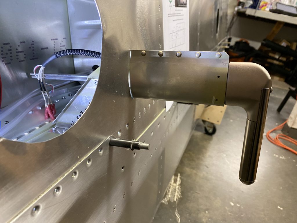
First test fit shows that the masts are too long and need to be cut further.

In the end, I had the masts cut down to right around 8 1/2 inches. The Garmin manual says to keep a minimum of 8 inches between the probe and transition to non-metalic tubing, so I had a little bit of margin.

Time for flaring the tubes. The AN fittings use a 37 degree flare, so I got a Rigid 377 flaring tool and a metal tubing cutter to cut the tube. Before doing this on the real Pitot Tube, I made some test flares on a spare tube I bought from Aircraft Spruce.
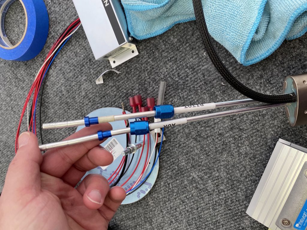
Make sure you put the AN fittings onto the tube before you do the flaring (I may or may not have forgotten it the first time and cut and redo the flare once).

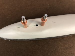
After I had that dialed in, I did another test fit to get the length correct, accounting for the bend towards the tube and then mounted the fittings.
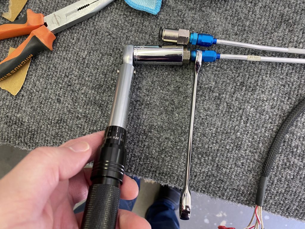
Mounting the fittings to the tube.

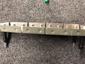
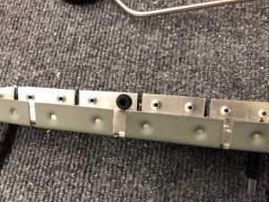
Final fit and connecting to the nylon tubes inside the wing after having cut the nylon tubes.
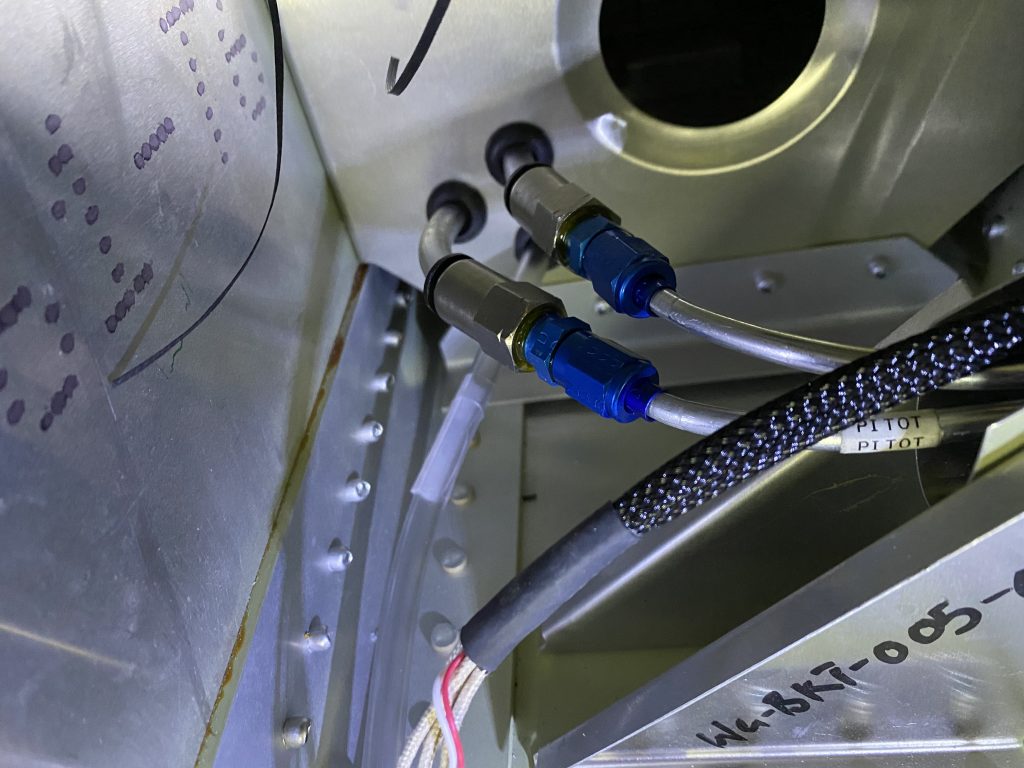
Final fit and connecting to the nylon tubes inside the wing.

Installing the regulator and wiring

With the Pitot Tube itself installed, time to finish the regulator and wiring that controls the heating of the Pitot Tube.

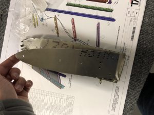
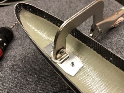
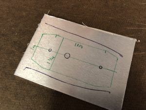
As I explained previously, I plan to mount the regulator unit onto the inspection panel plate, so I did some measuring and orienting to make sure the twist action of the round plate wouldn’t interfere with the wires coming out of the regulator.

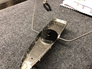
Here is the final orientation that I figured out would work best (the screw will mount to the bottom, so the wires will come out the top):
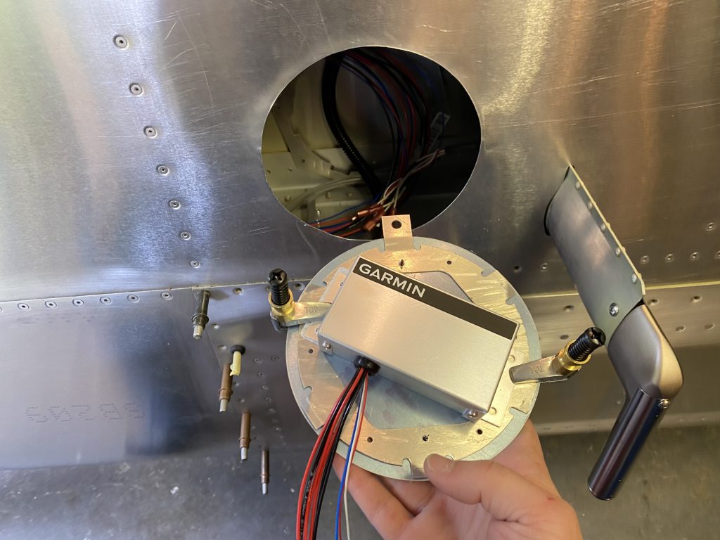
Here is the final orientation that I figured out would work best (the screw will mount to the bottom, so the wires will come out the top).

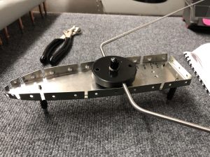
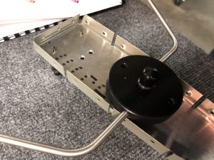
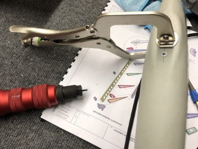
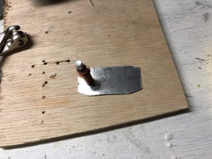
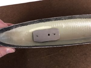
I contemplated between screwing or riveting it on, but I figured that it’s unlikely that it will need to be changed out frequently, so I riveted it onto the plate.
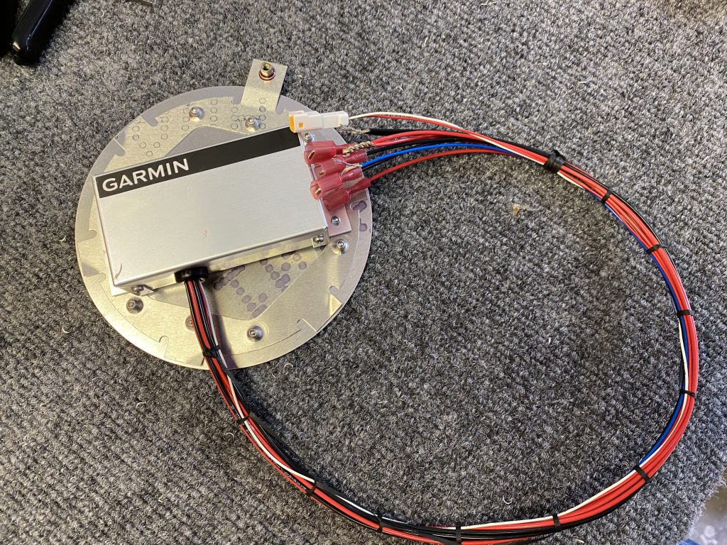
Completed inspection panel plate with the Garmin Regulator mounted.

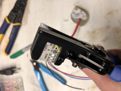
The last part was to create a connection from the regulator to wires I ran through the wings. I used some weatherpack connectors for this, which create a waterproof connection and a solid crimp, similar to the Delphi GT 150 that Midwest Panel uses to connect the wiring harness.
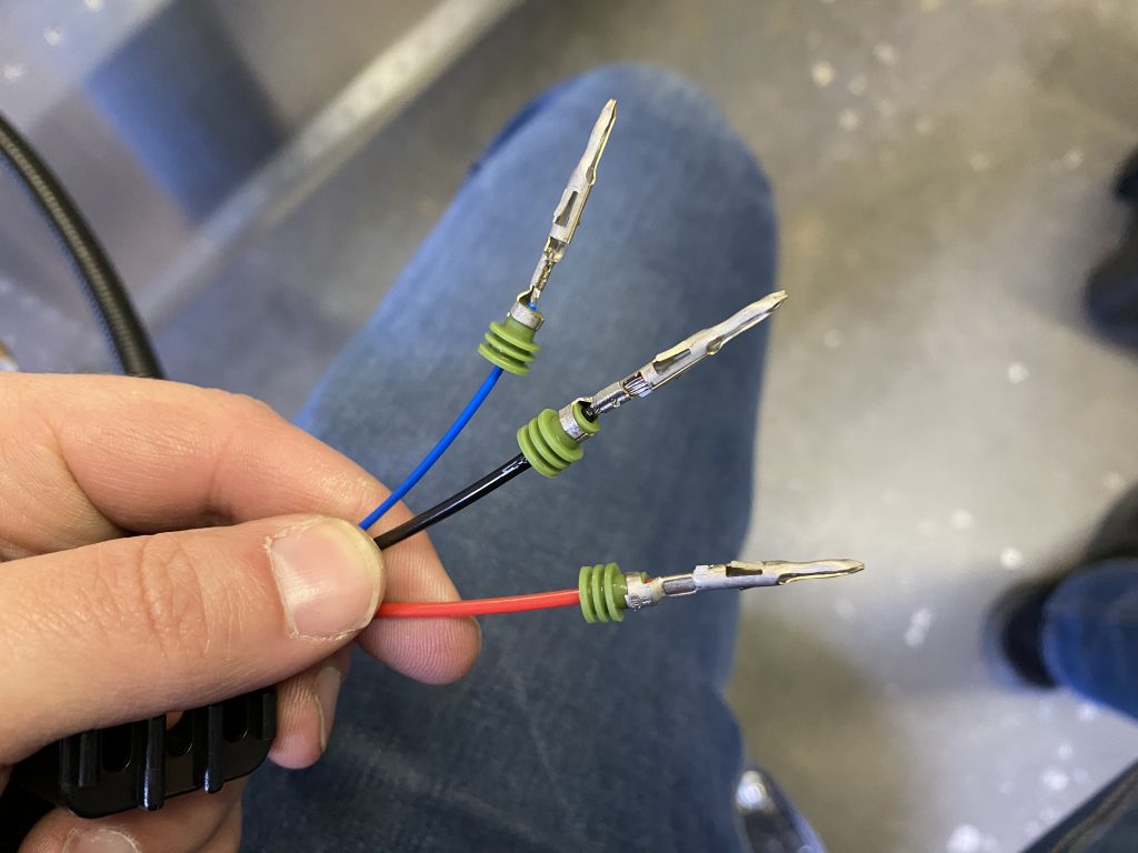
Crimped wires to connect to the regulator (blue connects to the panel to communicate with the G3X to see whether Pitot heat is active)

Final completed connection between the regular, the Pitot Tube and the wires running to the center.
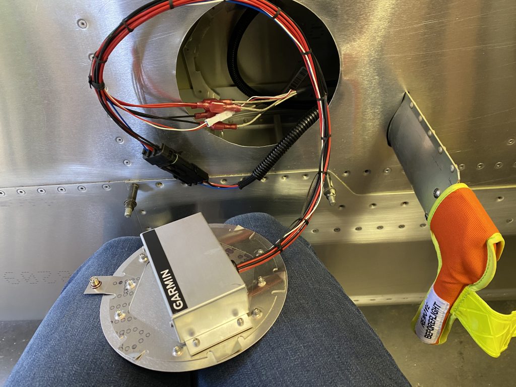
Final completed connection between the regular, the Pitot Tube and the wires running to the center.

Installing the plate to the wing

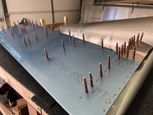
The last and final part of the installation was to mount the inspection panel plate onto the wing. I did this last to prevent scraping up my arm while I had to do all the mounting inside the wing, since the backing plate that holds the plate in place has a series of pokey corners that love to eat airplane builder blood.

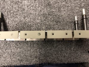
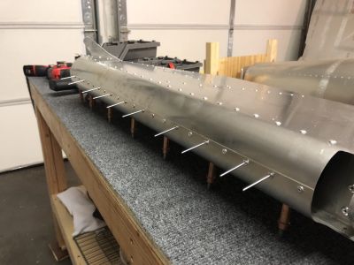
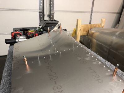
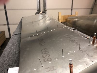
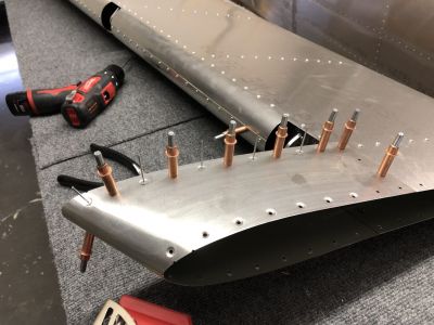
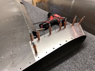
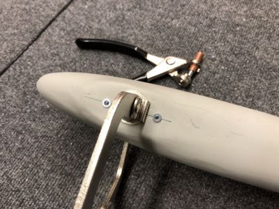
First I lined up the plate with the wing and then did the match drilling of the holes:
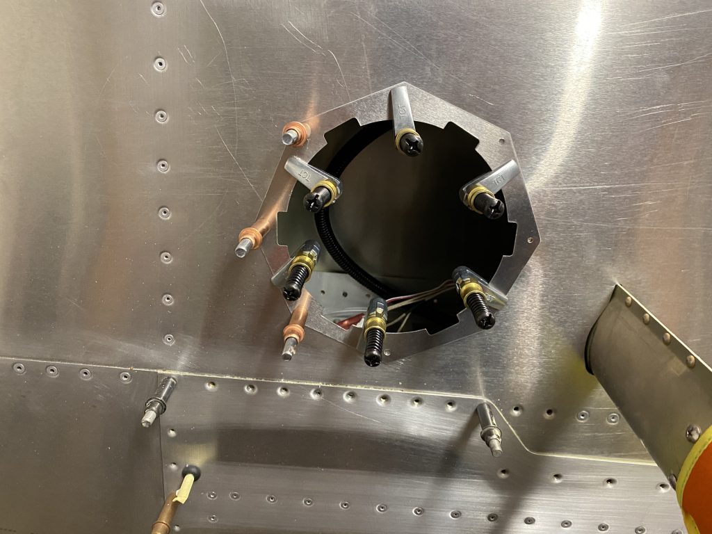
First I lined up the plate with the wing and then did the match drilling of the holes.

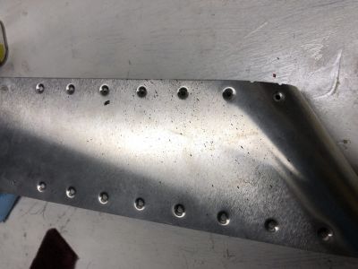
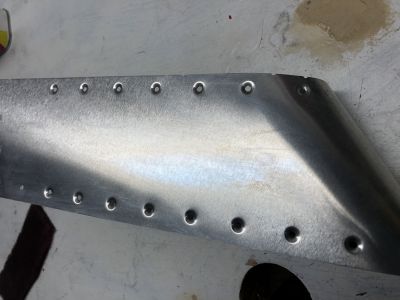
The I dimpled the plate and the matching holes on the wing and riveted it in place.
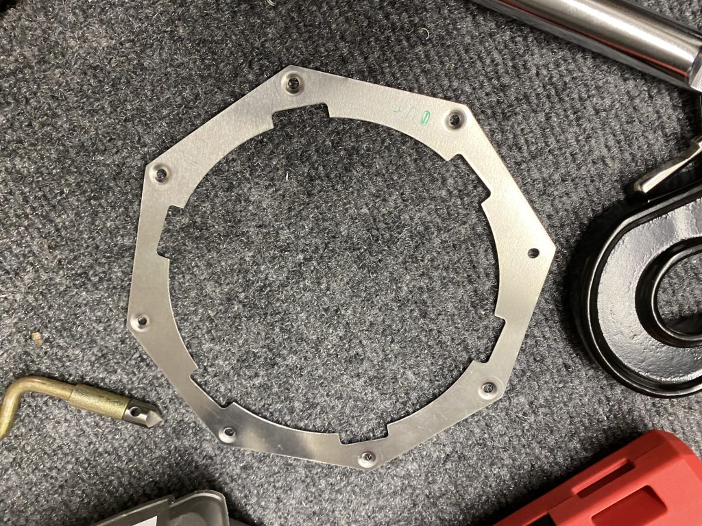
The I dimpled the plate and the matching holes on the wing and riveted it in place.

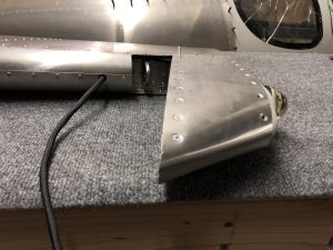
And here is the completed and closed up Pitot Tube and Inspection Plate that holds the regulator:
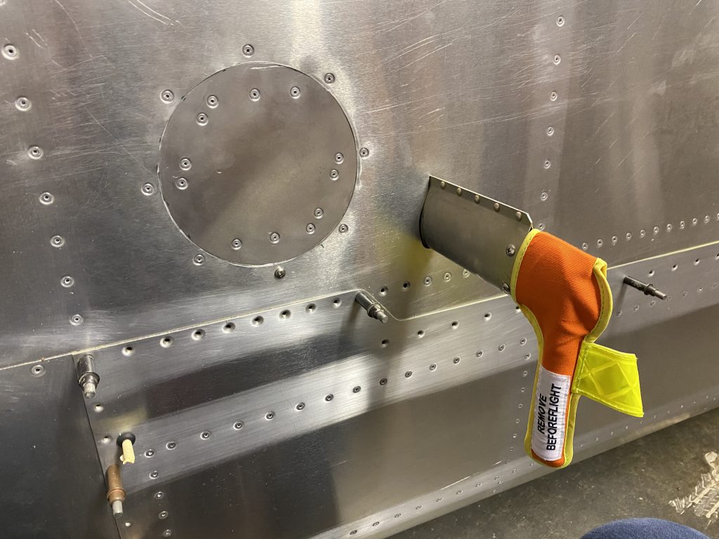
And here is the completed and closed up Pitot Tube and Inspection Plate that holds the regulator.

Timelapse of the entire installation

Pitot Electrical Wiring

Hours: 5
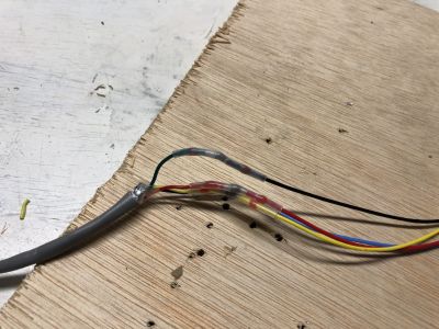
After cutting the hole for the inspection panel a few days ago, I continued and ran the wires for the heating.

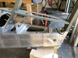
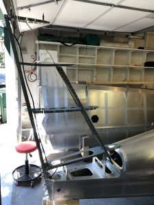
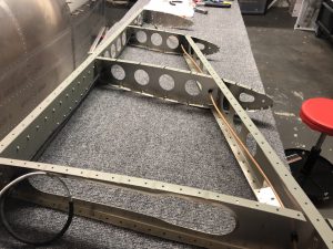
I figured out where I want to run the wires a while back after some tinkering and I am using one of the strut channels for the length of the wing, except the very end at the wing-walk where I had to make one curve down the bottom.

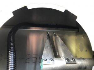
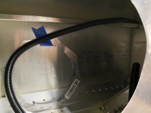
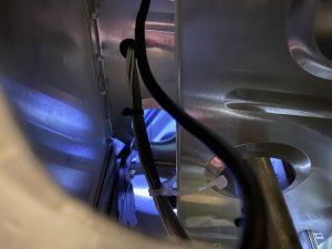
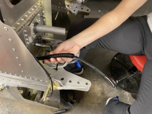
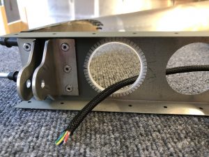
After some trial and error, I found that 3/8 in size wire loom tubing fits perfectly in the channel and with the help of my Wireless Endoscope connected to my phone I was able to finagle it through the wing with some mild scrapes on my arms.

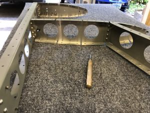
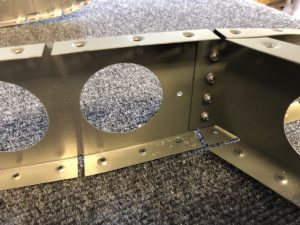
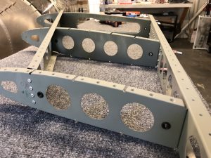
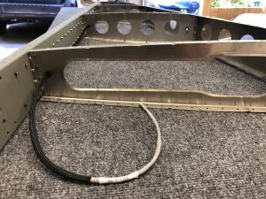
Starting to run the wire loom  Wire loom at the new Pitot Inspection hole Fishing for the loom (very bottom with the pliers)

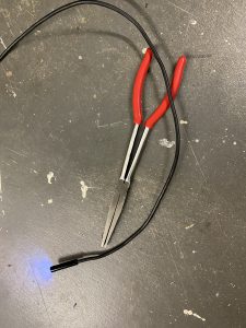
The hardest part was figuring out a good way to come out the bottom where the wing-walk is, since the strut channel doesn’t go through there. On the last picture above, you can see when I finally managed to grip on to where I want the loom to come out of with the help of some duckbill pliers, which were a suggestion from my EAA chapters Technical Counsellor when he visited a few months ago.
Duckbill pliers to the rescue

Running the wire

With the question of where to run the wire solved, onto actually running the wires.

I am installing the Garmin GAP 26 Heated/Regulated Pitot Tube, which comes with a Regulator that needs to be installed next to the Pitot tube and controls whether the Pitot tube actually needs to be heated.

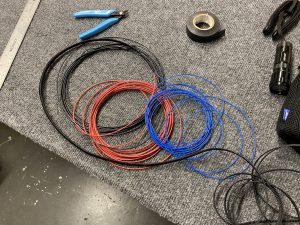
For this, there are three wires to run – two for the power and one for the discreet output, which integrated into the Garmin G3X Panel to show when the Pitot Tube is actually heated.

I ran the three wires through some braided sleeving to give them some extra protection and make running them through the wire channel easier in one go.Feeding the 3 wires into the braided sleeve

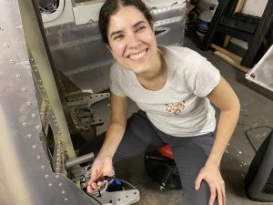
With that out of the way it “just” took a lot of back and forth, more use of the Endoscope and the thin arms of Juliana and repeated shouts of “push, push” and together we managed to run the wire all the way. She cheerfully pronounces “Congratulations, it’s a wire” as it came out the other end.
My friendly helper to run the Pitot wiring Congratulations, it's a wire

EAA SportAir Electrical Systems & Avionics Workshop

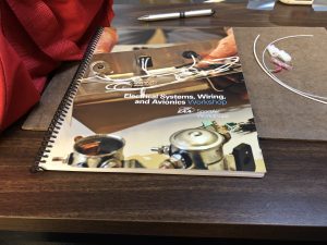
This past weekend I attended the EAA SportAir Electrical Systems & Avionics workshop at the Seattle Museum of Flight Restoration Center.

The two day workshop helped in explaining principles of airplane electrical systems, wiring and bringing everything together to design and build out your avionics.

Workshop Handbook

Aside from a lot of good learnings and explanations, there was also a couple of hands-on exercises to get familiar with crimping, soldering and connecting things.

The first exercise was to hook up a headset jack to a PM1000 intercom system. This was very handy, since whether you decide to build all your avionics or not, you will most definitely have to do the headset connectors.

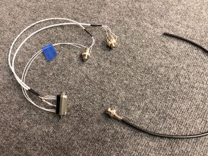
I forgot to take pictures of the process, but here’s the finished headset jacks with the soldered connection. This included learning to ground the shielded wire, soldering the actual headset jack and doing some d-sub crimping for the intercom connector.

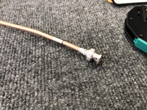
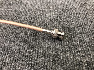
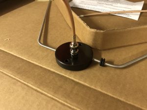
Finished Headset connector and crimped BNC Antenna connector

Also shown in the image above is the result of the second exercise, a crimped BNC antenna connector. This part, I was already familiar with from hooking up my NAV Antenna in the Rudder a few months ago.

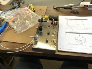
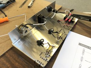
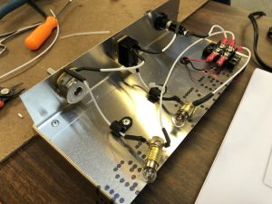
The final exercise was to create a small electrical circuit. This includes a “master” switch, circuit protection in the form of a fuse and a dimmable “cabin” light that is tied behind the master switch. Aside from the practical application of the exercise, it also tied together a lot of the theoretical parts of the workshop and was a great finish for the weekend.

Getting started Wiring in progress System wired up

Here’s the finished working circuit in action:

I also ran into two other Sling Builders, Richard Howell, who recently started building a Sling 2 and Skip Jones, who is also building a Sling TSi. Now we just need to all finish building our airplanes and then we can be a chapter of Sling Pilots in the Pacific Northwest.

Technical Counselor visit & Vertical Stabilizer Antenna wiring

Hours: 5

This morning I had my first visit from my local EAA Chapter 84’s Technical Counselor to look over my build and give me some advice as part of EAA’s Technical Counselor program.

This was the first Sling kit for him and he was impressed by the quality of the kit, its completeness and the instruction plans. We looked over my completed parts of the Empennage and talked about wiring, avionics and things to look out for. He also gave me some good general advice and stressed the point of documenting, particularly around wiring, since many years down the line there’s nothing worse than finding a wire and not knowing what it is for exactly, so he was happy to see my label maker and my active use of it.

We filled out the visit report and agreed to meet again after I’m further into the build and working on the interior of the Fuselage.

Vertical Stabilizer wiring

Now, back to building. As I finished the match drilling of the dimpled holes the other day, I had to dimple the hole that was missing a dimple, so I got out my modified hand dimpling tool and quickly did that dimple.

After that I worked on finishing the wiring the run through the Vertical Stabilizer for both the Anti-collision light on the Rudder, as well as the NAV Antenna.

First I had to make another hole to run the Antenna wire through the top rib since the factory plans assume that you either install the light or the Antenna, but not both. I marked the hole location using the center punch, then drilled a pilot hole and then used my step-drill bit to up-drill the hole to the right location for the snap bushing to go in.Center punch to mark the hole location Pilot hole drilled and ready to be drilled up using a step drill bit Finished hole and snap bushing installed

After that was done, I wrapped the wire for the light in some braided sleeving for some extra protection and then ran it through the rear holes. I also installed some flexible edge protection for the hole where the wire will meet the wire from the Rudder.
Wire for the light installed in the Vertical Stabilizer Flexible edge protection

Quick test fit on the Fuselage

I then quickly measured out the length of the Antenna wire to install in the Vertical Stabilizer, cut it to size and ran it through the front holes. After I was done with that, I wanted to do a quick test fit of the Vertical Stabilizer Structure on the Fuselage to see where the holes would pass through.

Quick test fit to see where the wires come out Looks almost like an airplane

Antenna Coax wiring

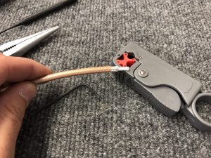
Once that was figured out, I moved on and did my first crimped coax connection. After a tip I saw on the homebuiltHELP channel, I bought this rotary coax stripper, which strips both the front, as well as the braided shielding in one go.
Rotary coax stripper

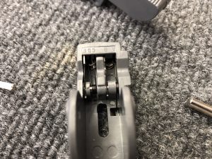
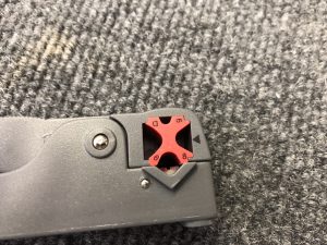
Before it was ready to use I had to do some adjustments for the lengths and depths for the cut, so I took it apart, while following the instructions and then moved the blade as needed. I’m using the SteinAir BNC Connectors, so I had to move the blade that exposes the outer shielding back by one position to the point marked E and the inner blade on mark B.
Blades set on mark E & B for the SteinAir BNC Connectors Correct location for RG400 stripping
Then I adjusted the blade depth using the screws on the bottom and did a few test cuts to make sure the results are repeatable. I then put some light strength thread locker on the screws so they stay in position so I can now just use it without any further adjustments needed.

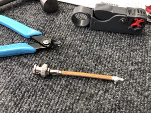
After that I did a quick test crimp of a connector to the small piece of wiring I used to calibrate the wire stripper, following the instructions from SteinAir.
Test crimp successful

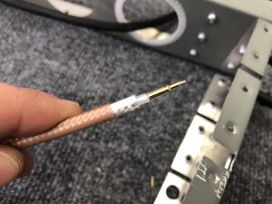
Looked all good, so I repeated everything on the actual wire for the Vertical Stabilizer.Wire stripped and ready to install the center tip Connector attached and ready for the back shielding to be crimped Completed crimp of the connector Test fit of the connector on the Antenna

With all that done, I installed the wire in the Vertical Stabilizer and now I’m ready to install the Antenna and close up the skin.

Interesting side note on coax wiring and the use of a balun

One other interesting thing I learned while doing this – I tested the wire I crimped for continuity to make sure there are no problems with the wire itself by checking (lack of) continuity between the shielding and the center core. This was all good, so my crimp is good.
After attaching the wire to the Antenna however, I figured I’d also check it with the wire attached to the Antenna and had a brief moment of confusion when I did get a positive continuity readying between the core and the outside. So I did some digging and found out that the use of a balun (in my case with the Rami AV-525, it is an internal balun) can create a DC short and thus will produce a continuous reading using a Voltmeter.

Vertical Stabilizer Navigation Antenna Mount

Hours: 1.5

Now that the Rudder is finished, it’s on to the next few tasks. I received the reinforcement plate for the Rami AV-525 Navigation Antenna to go onto the Vertical Stabilizer, so I had everything to get that fit in place.

First I did a bit of test placements and confirming the correct alignments with the plans. Then I marked the hole that needed to be enlarged and the part of the opening on the opposite that needs to be trimmed back.
Reinforcement plate for the NAV antenna to mount into the Vertical Stabilizer Rib Test placing the Antenna on top Test placing the Antenna on top Hole marked for enlarging Area marked to be trimmed

Once that was figured out, I got out the step-drill bit and enlarged the hole for the Antenna to fit through. Then I trimmed back some of the other side for the second pole and deburred everything. Finally I put a grommet into the hole and some flexible edge protection for the other side and placed the antenna in for a test fit.

Grommet installed in the hole and side trimmed Rami AV-525 NAV Antenna in place

Rudder Anti-collision light wiring

Hours: 2

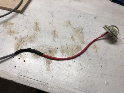
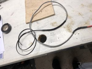
Now that the Rudder is almost complete, I needed to make the wiring for the Anti-collision light permanent. The existing wire of the Aveo Posistrobe Minimax I’m using has 4 wires (ground, power, strobe, sync), so I needed to splice those onto the wire so I could run it through the structure.

Since this is a permanent connection, I’m using Heat Shrink Solder Sleeves, which have solder in the center and when you heat it up, the solder melts and the sleeve shrinks down to create a good seal.

After that was done, I added some expandable braided Sleeving over the wire for extra protection.
Expandable Braided Sleeving for the wire

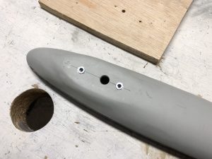
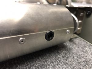
I up sized the hole for the wire to pass through the fiberglass tip using my step drill bits and then ran the wires through the structure and out the front hole, which I also had to drill up as per the instructions. After some more research, I replaced the rubber grommets with snap bushings. They last longer and for the front hole in particular, they hold on better since they snap in place.
Finalized hole size for the wiring to pass through the fiberglass tip Snap bushing for the wire to come out of instead of using rubber grommets

Here’s the light mounted and completed wiring done.Light mounted and wiring finished

Now the last thing to do is close up the top. Inspired by a discussion from a while ago on the Sling Builders group, I was contemplating the idea of making the fiberglass tip removable using nut plates and screws, but I think I’ll end up just riveting it closed.


Finishing the Rudder skin & mounting the light

Hours: 4.5

I spent some time over the past week figuring out Electrical wiring and Antennas, talking with Adam from Midwest Panel Builders who I am working with for my panel and wiring.

Aside from that I was working on finishing the Rudder and preparing for the next parts. Jean is sending me replacements for the dented ribs of the Vertical Stabilizer, so I can put that together next and the Navigation Antenna will arrive this week as well to get that going. I will be using the Rami AV-525 VOR/LOC/GS Antenna.

Riveting the skin went all pretty smoothly. I had to take off the front top skin one last time as I had a bit of overspray on the outside from priming. A little bit of scrubbing using MEK and it was all clean.

Mounting the light to the fiberglass tip

After I finished the skin, I worked on mounting the support plate I made earlier for the anti collision light on top of the fiberglass tip.
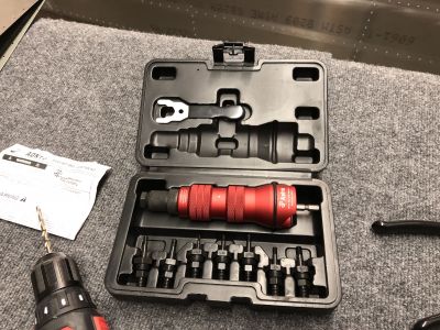
To pull the rivnuts I’m using the Astro Pneumatic ADN14 tool and Loctite 277 Threadlocker. It just mounts to the front of my drill and then you just need to hold the shell and the drill pulls in the rivnut.

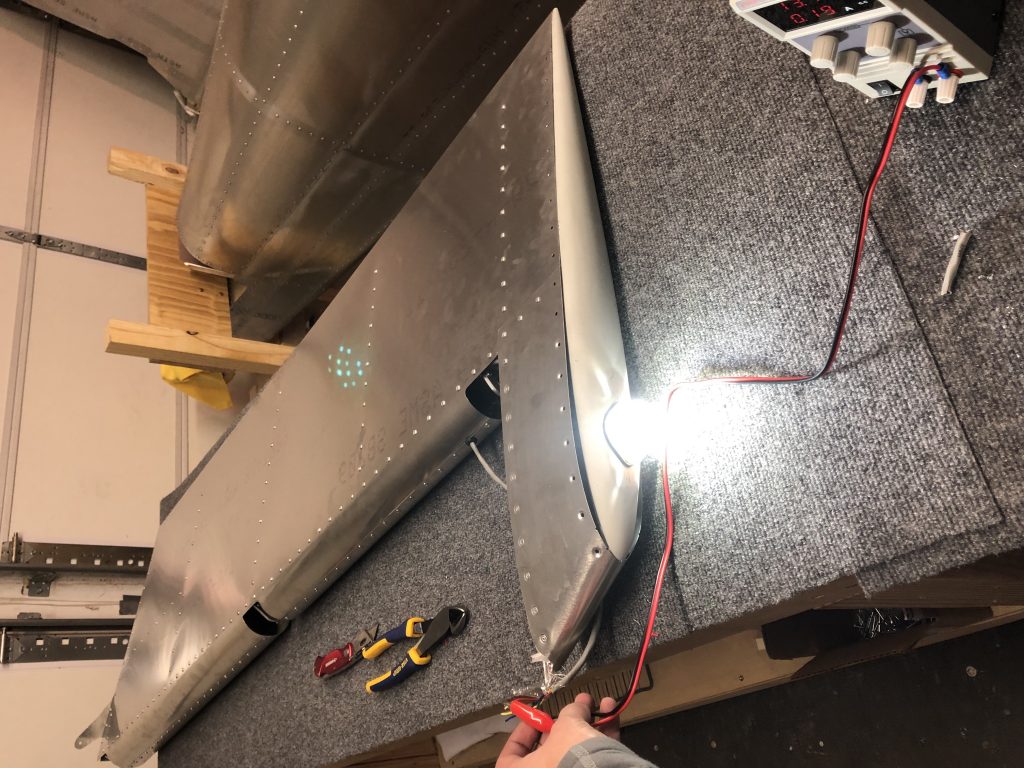
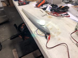
After all that was done, I temporarily mounted the light onto the Rudder and ran the wire through the structure. Then I brought over my DC Power Supply unit and made it shine brightly.

Testing the light in place using my bench power supply

Rudder skin fitting & Anti-Collision light mount

Hours: 3

Over the past few days I spent some time organizing the next few parts of the Empennage such as organizing the Vertical Stabilizer parts and what I needed to finish for the Rudder.

Fitting the Anti-collision light

I got the Aveo Posistrobe MiniMax anti-collision light to mount onto the rudder tip and started working on fitting it on.
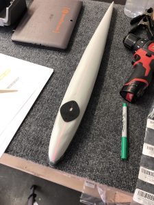
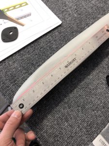
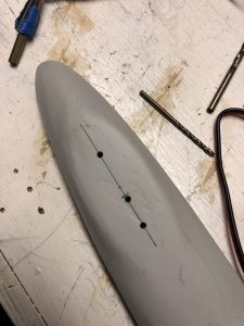
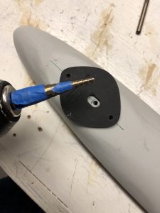
Aligning the strobe light seal to find out where the holes should go Marking center linePilot holes drilled Double checking the holes aligned properly and then enlarging the hole for the wires to pass through
Light temporarily on top and shining bright like a diamond.
Quick test with light on

Mounting plate

The first iteration of the Empennage assembly instructions called out for a mounting plate to go inside the fiberglass tip to add structural reinforcement for the rivnuts, but the latest version of the instructions is missing it, so I sent a question to the factory why.

In the meantime, since I assume that it’s still a good idea since both the Sling 4 instructions as well as the first version of the instruction call for it, I decided to fabricate my own.

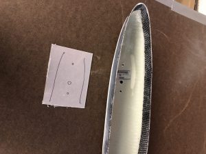
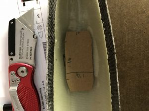
I started tracing out the rough dimensions of the area and then measured it down to how it would fit. Then I made a first version out of cardboard to see if the dimensions I estimated would work.
Rough outside dimensions of the strobe light traced Test fit of cardboard cutout

Looked good, so then I copied my cutout onto the sheet metal and went to work cutting it out. I used a OLFA Scoring knive to score the cut, based on a tip from HomebuiltHELP. Since my metal was pretty thick I only scored it with that and then used metal snips to cut it, but for thinner metal you can actually make the whole cut using the scoring knive to make great straight cuts.Transferred cutout onto aluminum sheet Metal piece cut and ready to drill the holes

After that, I deburred all the edges and the holes and then checked the final fit in the rudder tip.Plate fits great in the tip Clecoed in place

Fitting the skin

I also test fitted the skin onto the rudder and checked how the tip will fit in. The skin came on fairly easily, but I will have to trim a little bit of the fiberglass tip so it will fit in.
Skin fitted and fiberglass tip put in place Need to trim off a bit of the rear of the fiberglass tip

I still had to prime the inside of the skin, so now that I know it all fits together fine, I will rivet the skin on and then work on the final trimming for the rudder tip so it fits in and then I will need to match drill the holes into the fiberglass tip and countersink the front holes.

Leveling the playing field

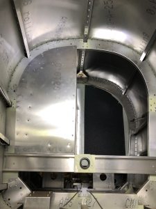
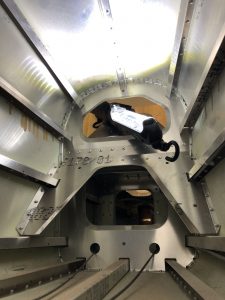
Not much progress, but I took a couple of closer looks at the tailcone of the Fuselage and ran some fishing wire through it for the VOR/LOC/GS wire from the tail.

Inside the Tailcone looking forward Inside the Tailcone looking aft

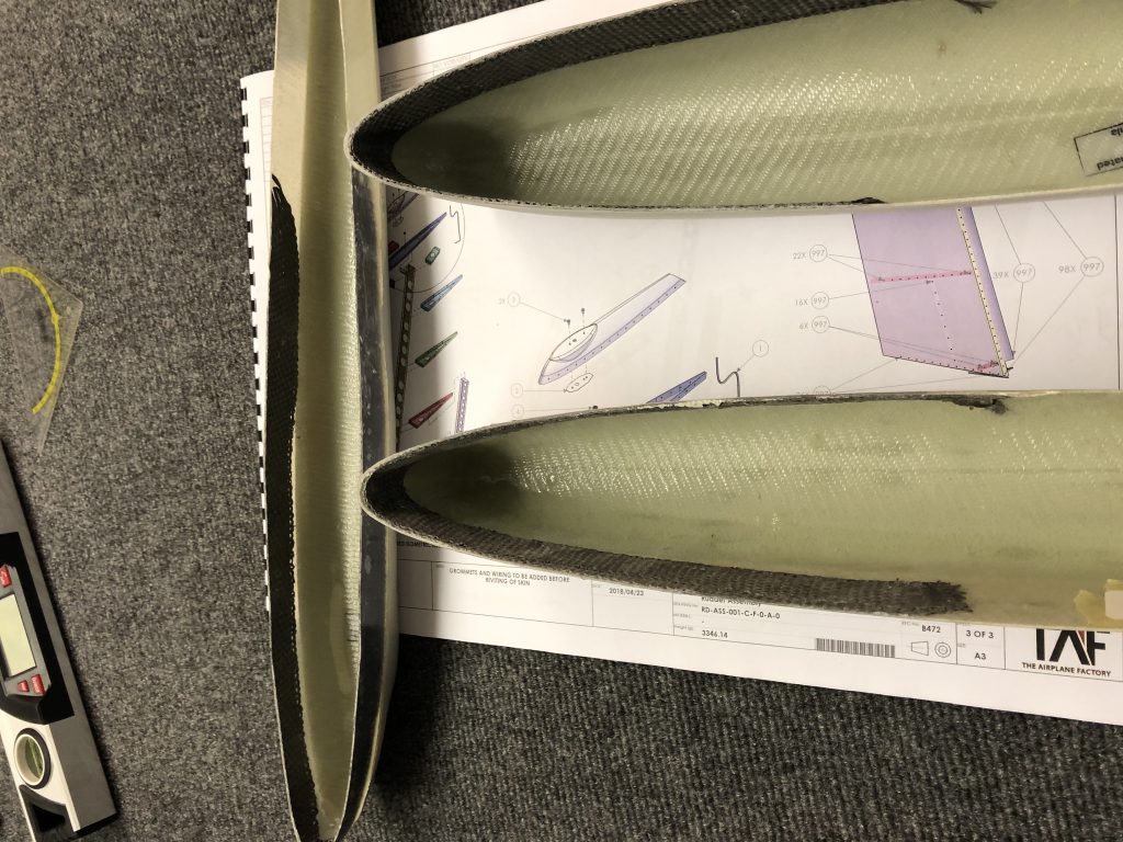
I also had an exchange with Matthew, one of the other Sling TSi builders, about the countersinking and fitment of the tips for the elevators and rudder. It looks like he is missing the reinforcement on the tips that adds material to allow the countersinking. I took some pictures of mine which shows the extra layers of fiberglass (in black) to allow enough material to countersink the tips:

Rudder and Elevator tips reinforced material for countersinking

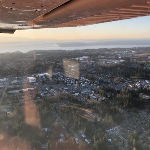
Today is one of those few winter days with nice sunshine, so I went to the airport in the evening and did some pattern work and got a bonus moment when the Boeing Dreamlifter came in to land on the parallel runway.

Boeing Dreamlifter landing 34L at KPAE Boeing Dreamlifter landing 34L at KPAE

After getting home, I was doing some inventory and trying to figure out which part to put together next. I don’t want to close up the Rudder yet since I don’t have the light yet and want to fit that first. I got the Sealant I need to close up the Horizontal Stabilizer over the weekend, so I took that back out and put it on my workbench.

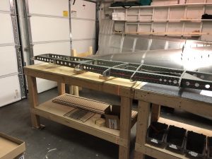
Then I got out my laser level to see if it all aligned and realized that my working surface is actually pretty slanted, so I spent some time to even out the tables. As it turns out, the garage floor has a pretty good slant as you can see below – 3 pieces of wooden shims on the far side, versus none on the near side.

Far side of the garage needed a few blocks of wood to level out the table Level table & Horizontal Stabilizer

Rudder structure riveting

Hours: 1.5

Now that I’ve prepared the Rudder parts with primer for the mating surfaces, it’s time for more riveting. I laid out all the parts and got to work assembling the Rudder structure.

Rudder parts ready for riveting Fitting the ribs of the Rudder

The strengthening plate is thicker and needed a bit more attention to deburr both the big center hole using my straight double edge deburr tool as well as the riveting holes. Most of the other holes were prepped well by the factory after checking them by running my finger over them.
The strengthening rib needed a bit of deburring

After everything looked good, I finished putting together the structure of the spar and all the ribs and lined up everything with lots of clecos.
Rudder structure laid out for riveting

And then it was time for another episode of riveting.
Riveting action Completed the riveting of the structure of the Rudder

I still have to buy the tail anti collision light that will go on top of the Rudder. I’m planning to get the Aveo Posistrobe MiniMax and then I’ll finish up putting on the skin.
Since I am planning on installing a VOR/LOC/GS antenna, I will run the wire for both the antenna, as well as the strobe light in one go through the Vertical Stabilizer as the instructions suggest.