This past weekend I attended the EAA SportAir Electrical Systems & Avionics workshop at the Seattle Museum of Flight Restoration Center.
The two day workshop helped in explaining principles of airplane electrical systems, wiring and bringing everything together to design and build out your avionics.
Aside from a lot of good learnings and explanations, there was also a couple of hands-on exercises to get familiar with crimping, soldering and connecting things.
The first exercise was to hook up a headset jack to a PM1000 intercom system. This was very handy, since whether you decide to build all your avionics or not, you will most definitely have to do the headset connectors.
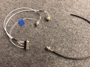
I forgot to take pictures of the process, but here’s the finished headset jacks with the soldered connection. This included learning to ground the shielded wire, soldering the actual headset jack and doing some d-sub crimping for the intercom connector.
Also shown in the image above is the result of the second exercise, a crimped BNC antenna connector. This part, I was already familiar with from hooking up my NAV Antenna in the Rudder a few months ago.
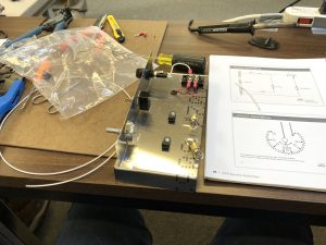
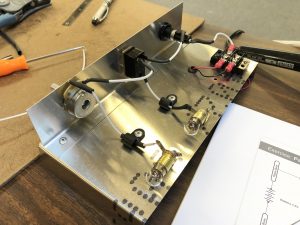
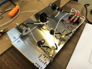
The final exercise was to create a small electrical circuit. This includes a “master” switch, circuit protection in the form of a fuse and a dimmable “cabin” light that is tied behind the master switch. Aside from the practical application of the exercise, it also tied together a lot of the theoretical parts of the workshop and was a great finish for the weekend.
Here’s the finished working circuit in action:
I also ran into two other Sling Builders, Richard Howell, who recently started building a Sling 2 and Skip Jones, who is also building a Sling TSi. Now we just need to all finish building our airplanes and then we can be a chapter of Sling Pilots in the Pacific Northwest.

Pingback: EAA Workshop – Sheet Metal | Richard's Sling 2 Build Log
Hi Philip! Cool post! Had a question about VOR – we started thinking about how to install the antenna on the vert. stabilizer and noticed that the plans don’t recommend running the VOR wiring through the vert stab *and* the strobe light through the rudder. Do you know why? Is it just for simplicity of wiring? Also, do you know if there is anything special about the coax wire used for the VOR or is it just a normal coax cable? Thanks!!
After discussing with Avionics shop, the only reason why you may not want to do it is if you were installing an old traditional high-voltage strobe, but with modern low power LED lights it’s no factor. So with that in mind, I decided to install both in the Vertical Stabilizer/Rudder, since that is also a bit more in line with my reading of the regulations around tail light positioning.
You can find the details about my wiring here and the Antenna installation here.