Tag Archives: Empennage

Horizontal Stabilizer skin fitting

Hours: 1.5

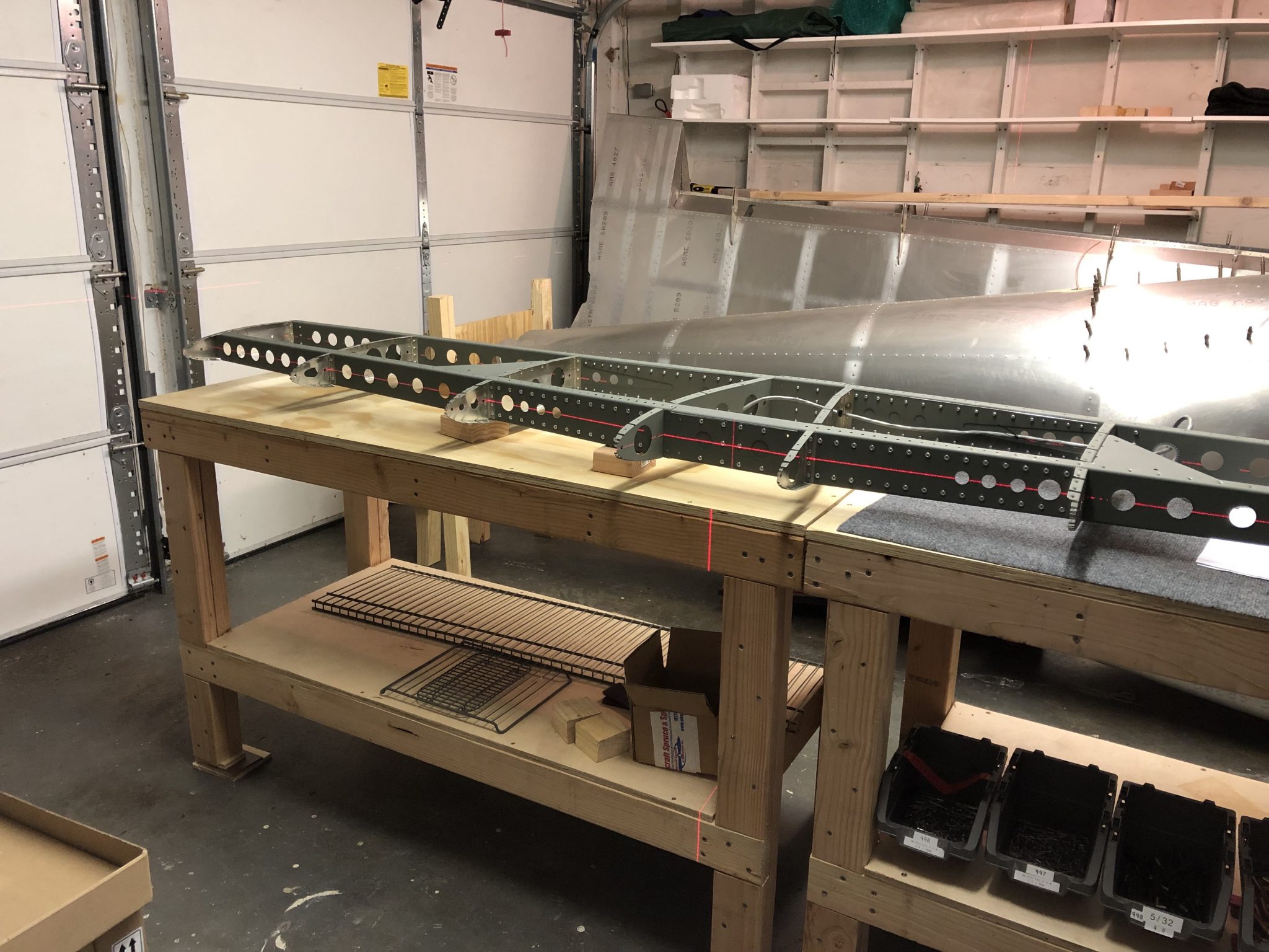
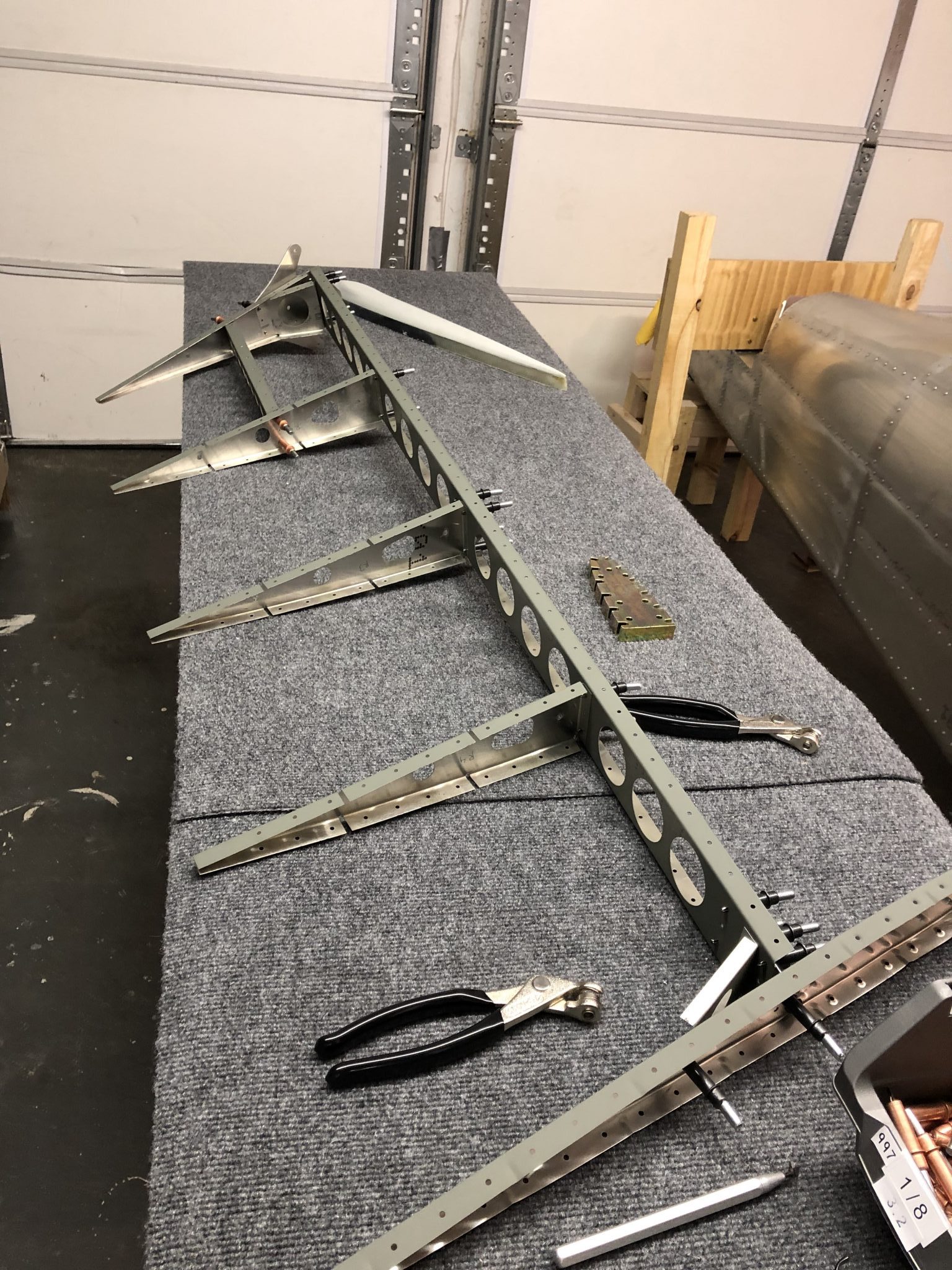
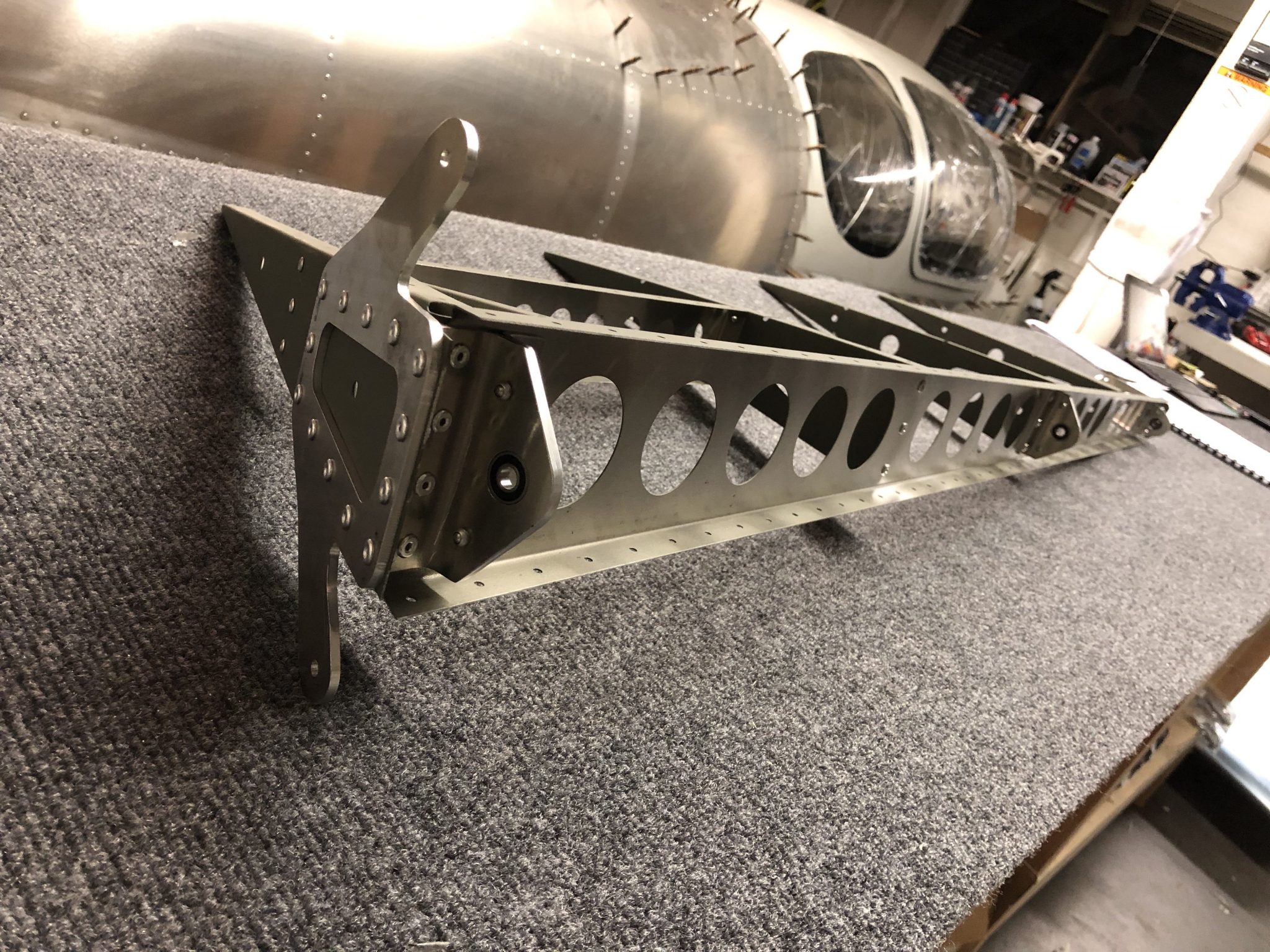
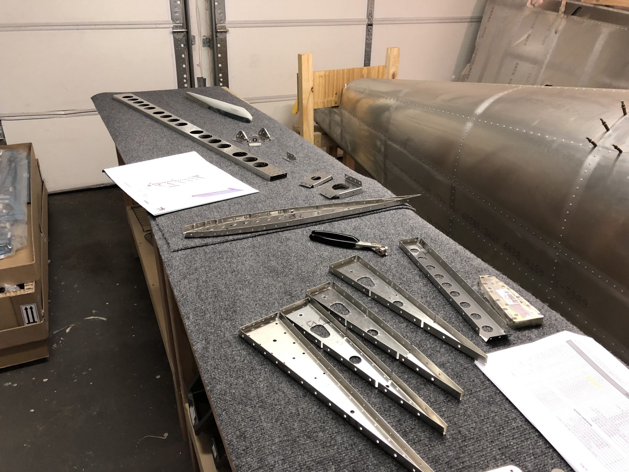
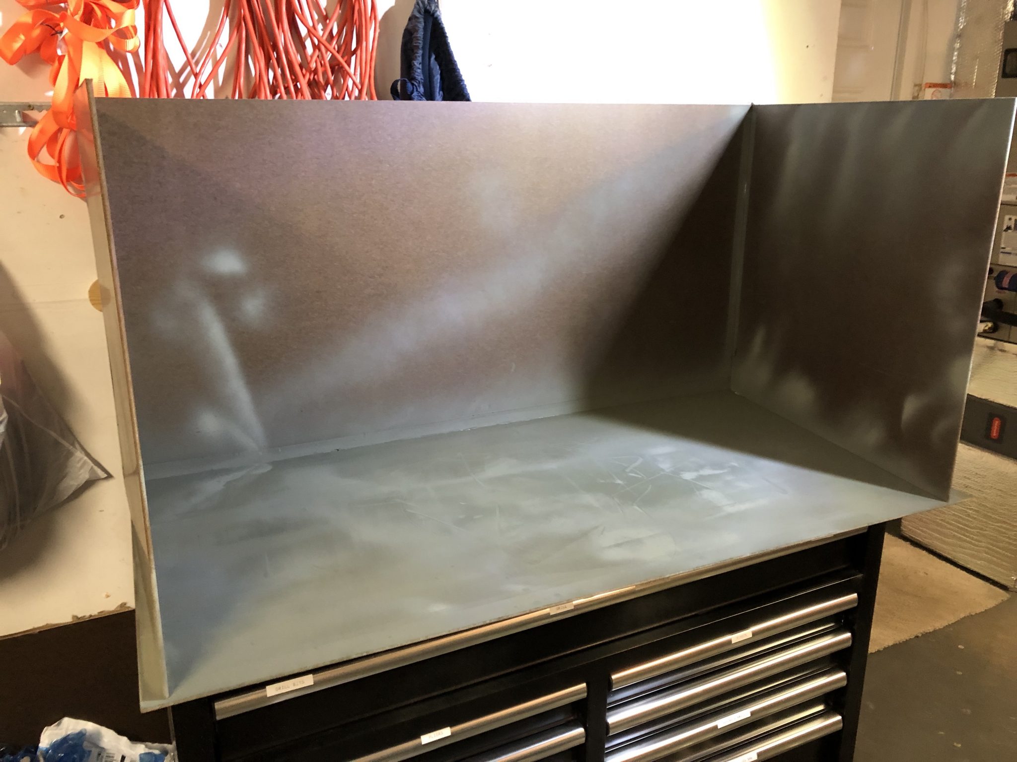
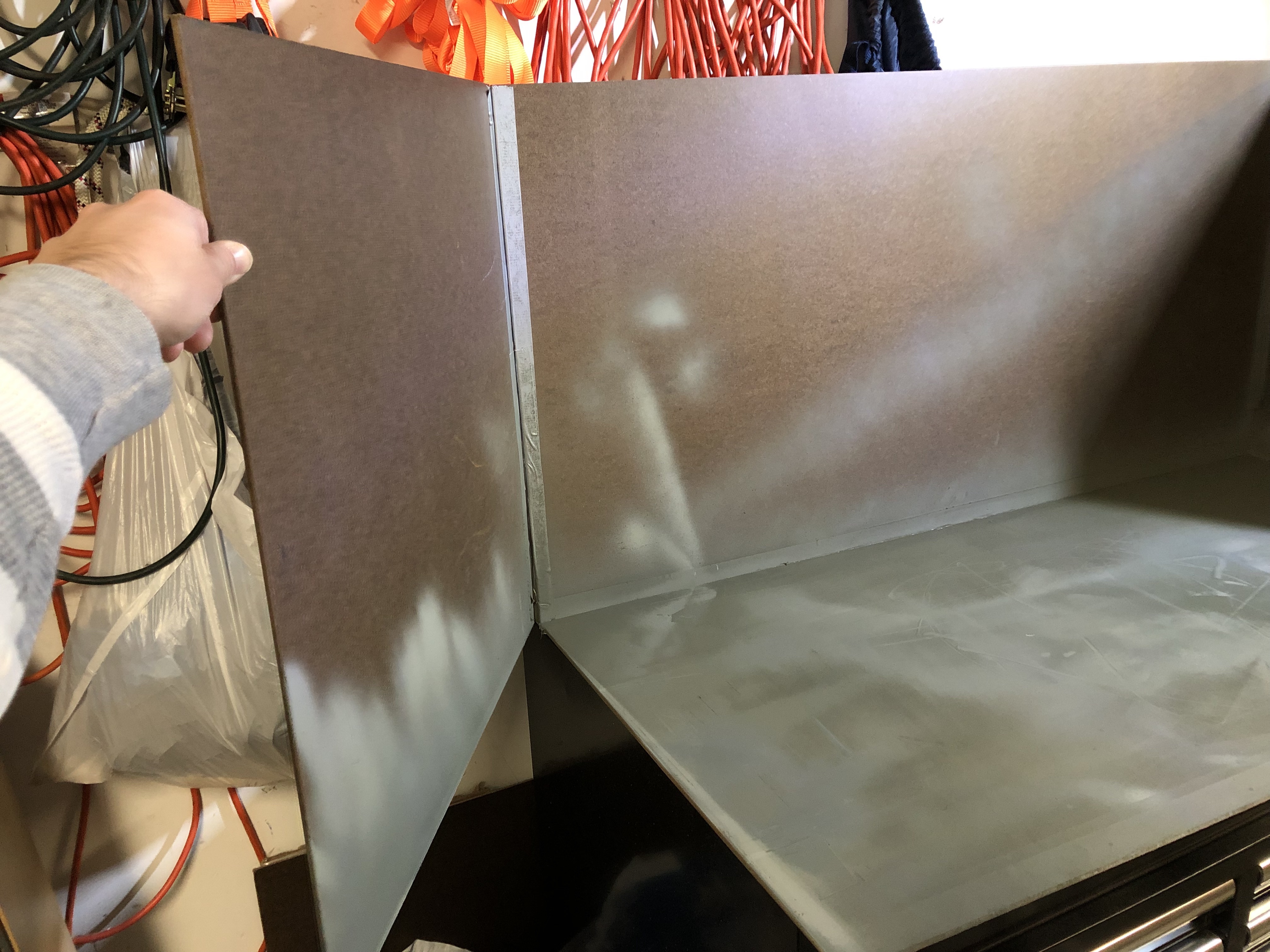
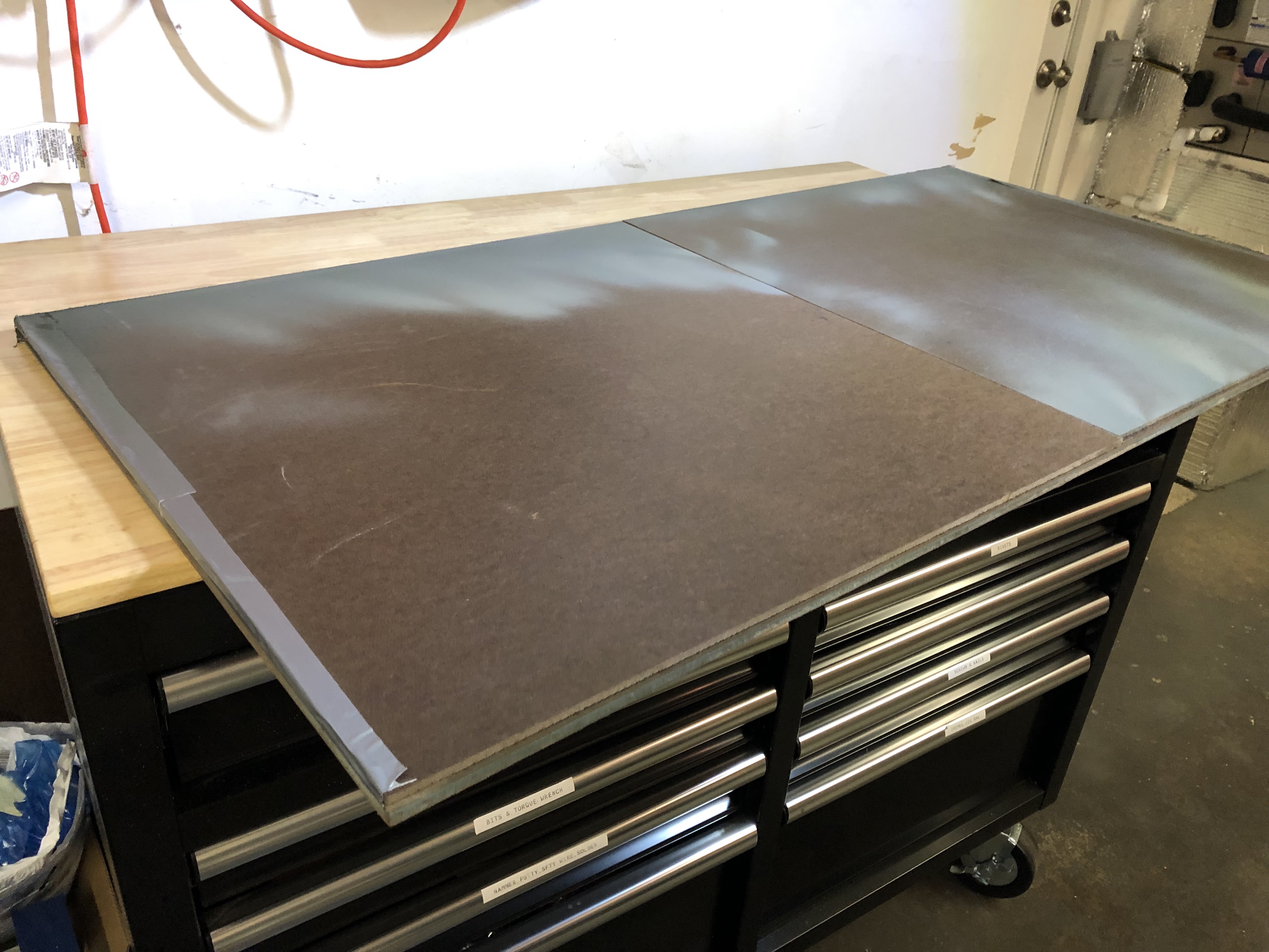
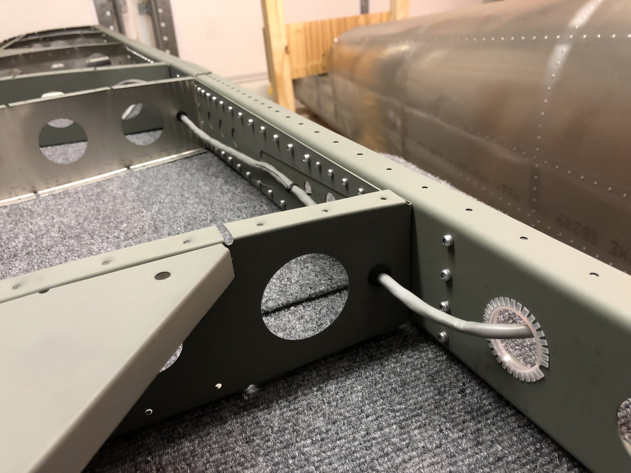
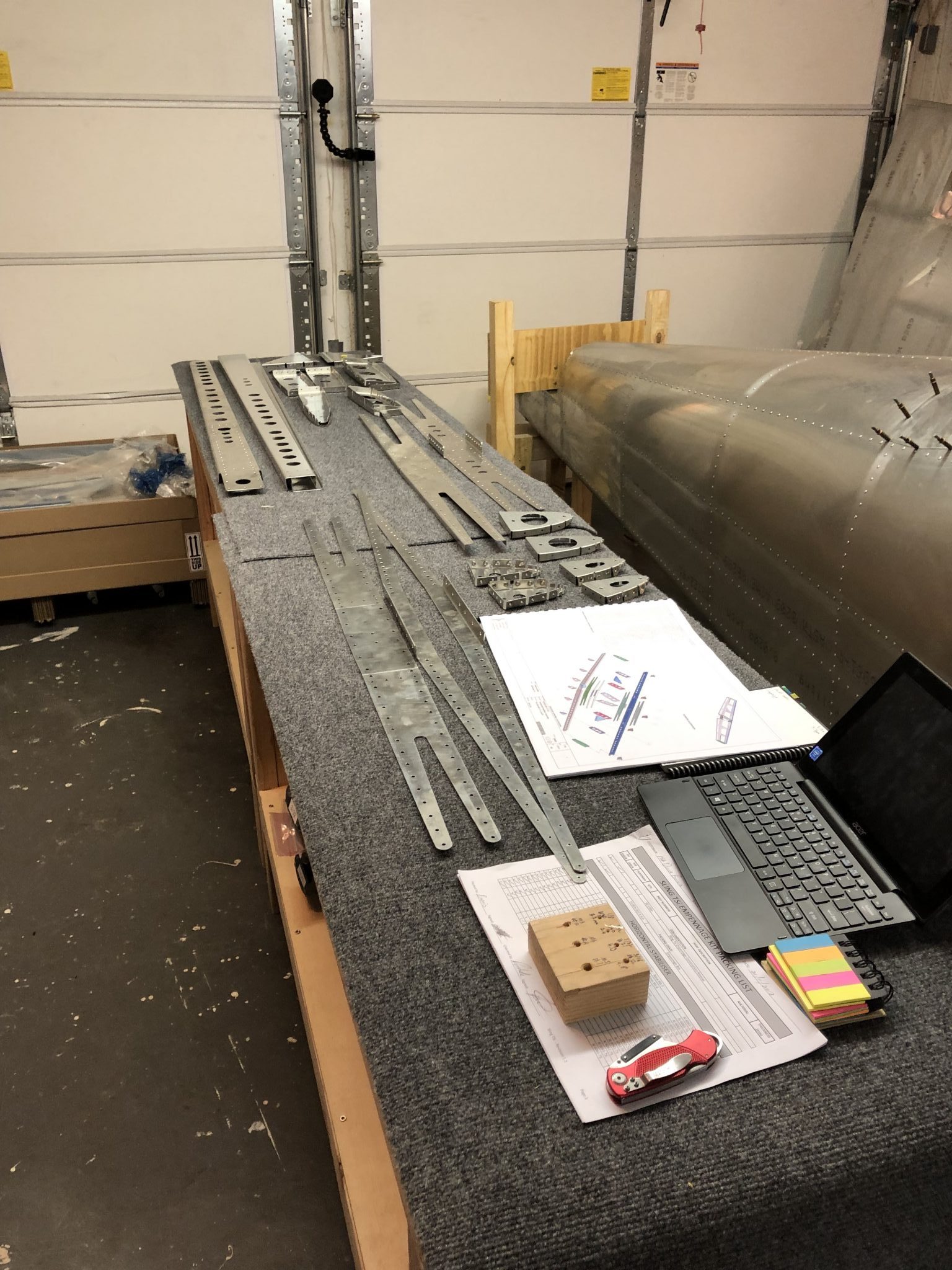
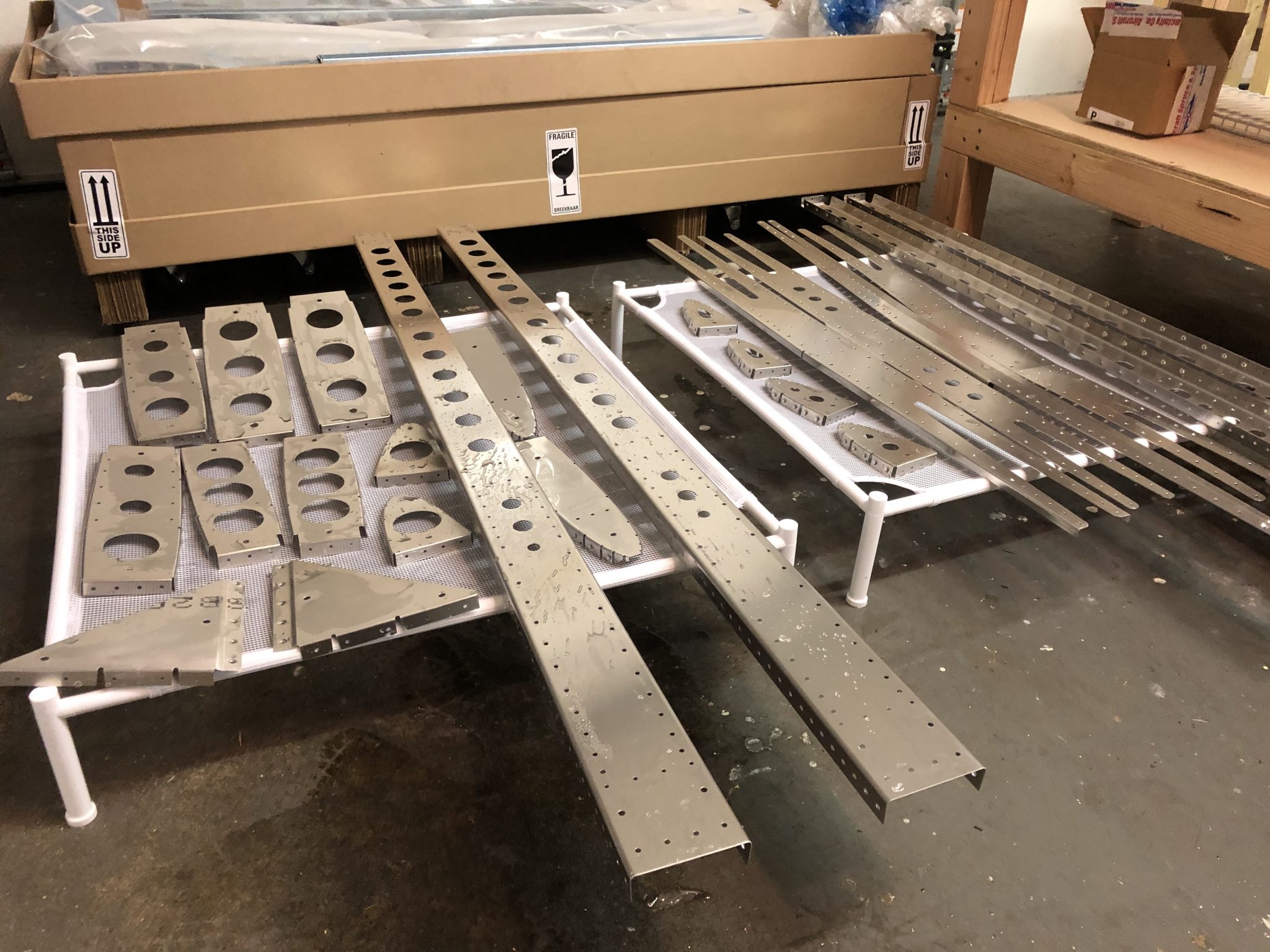
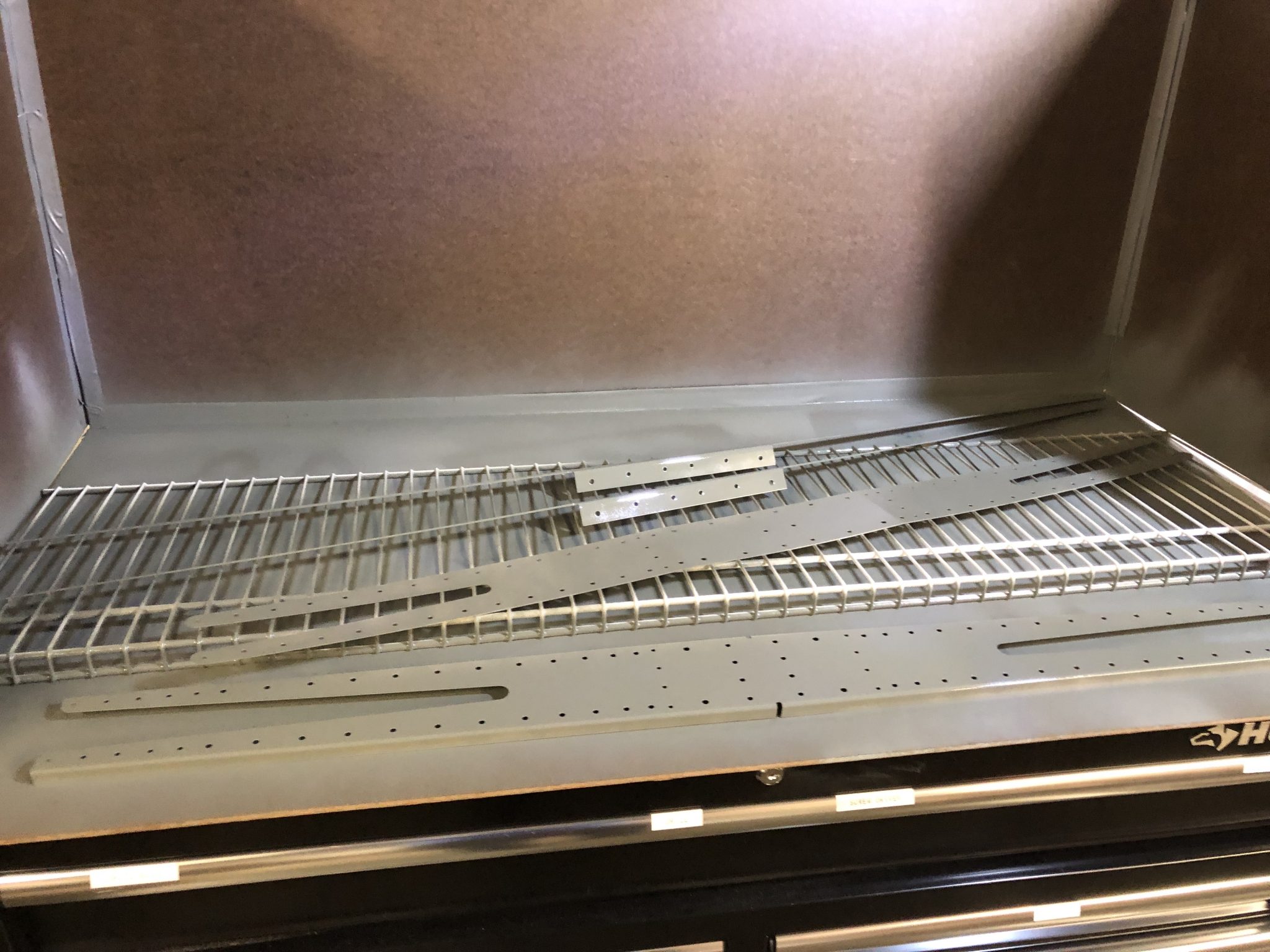
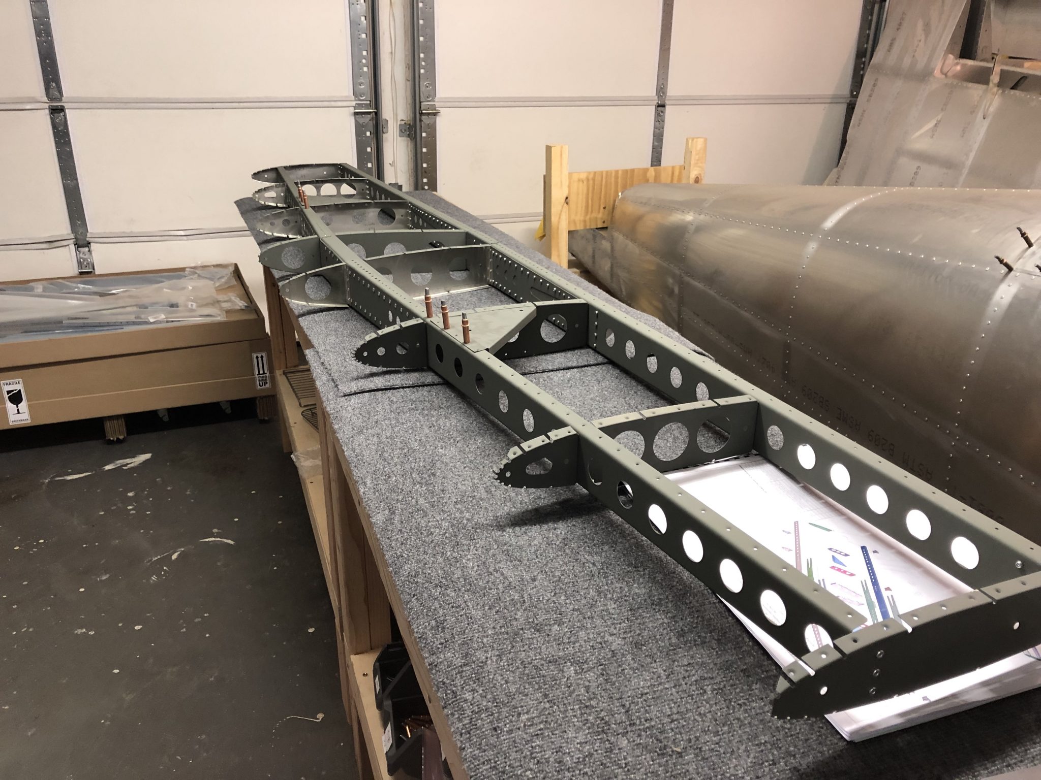
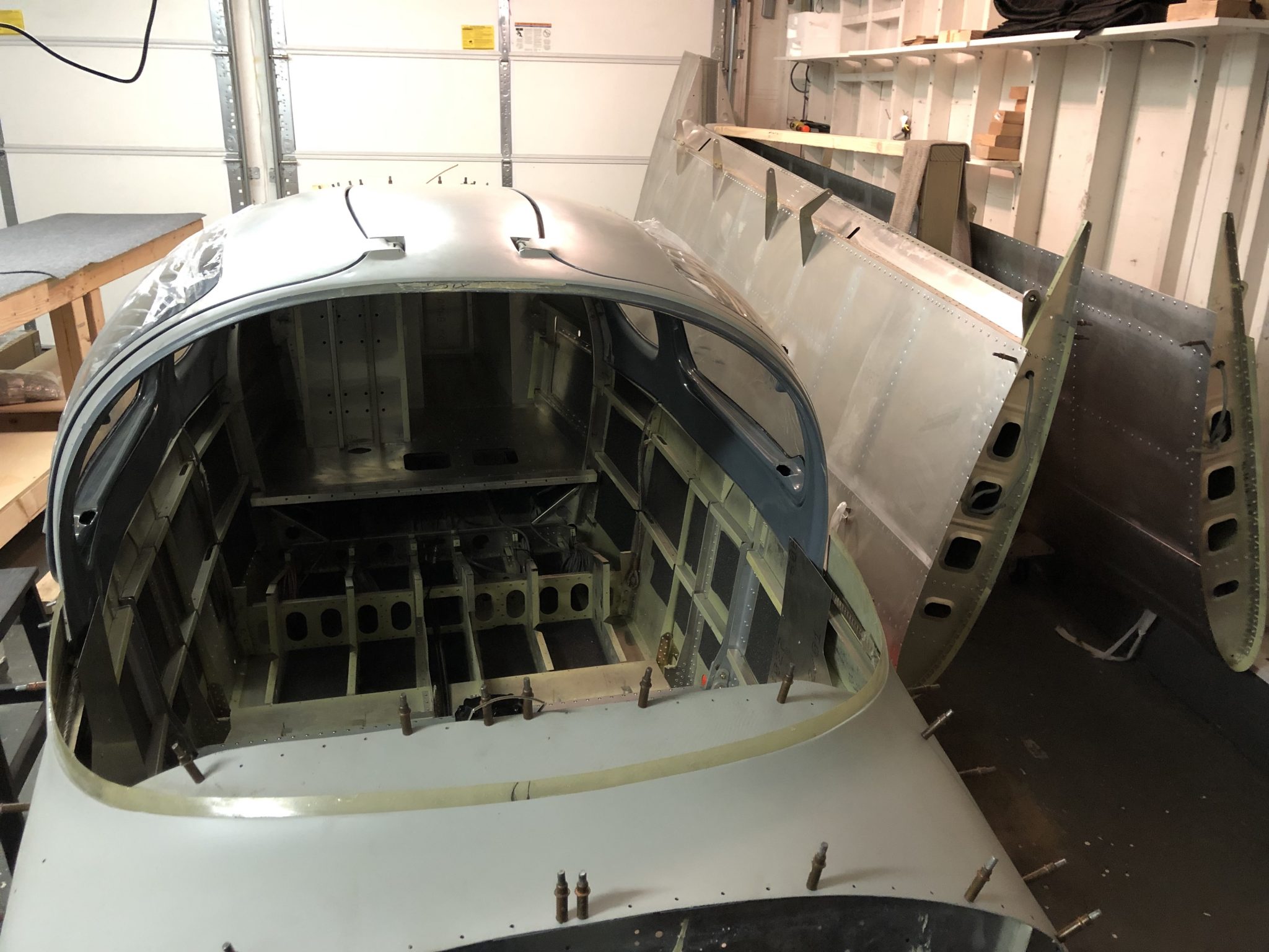
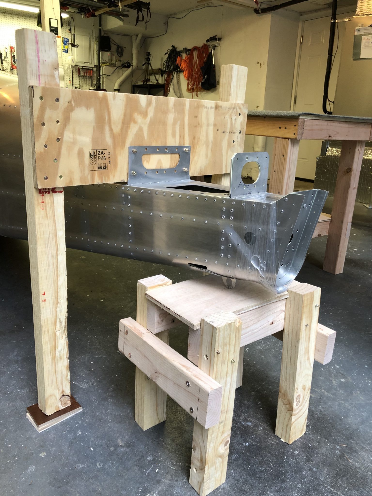
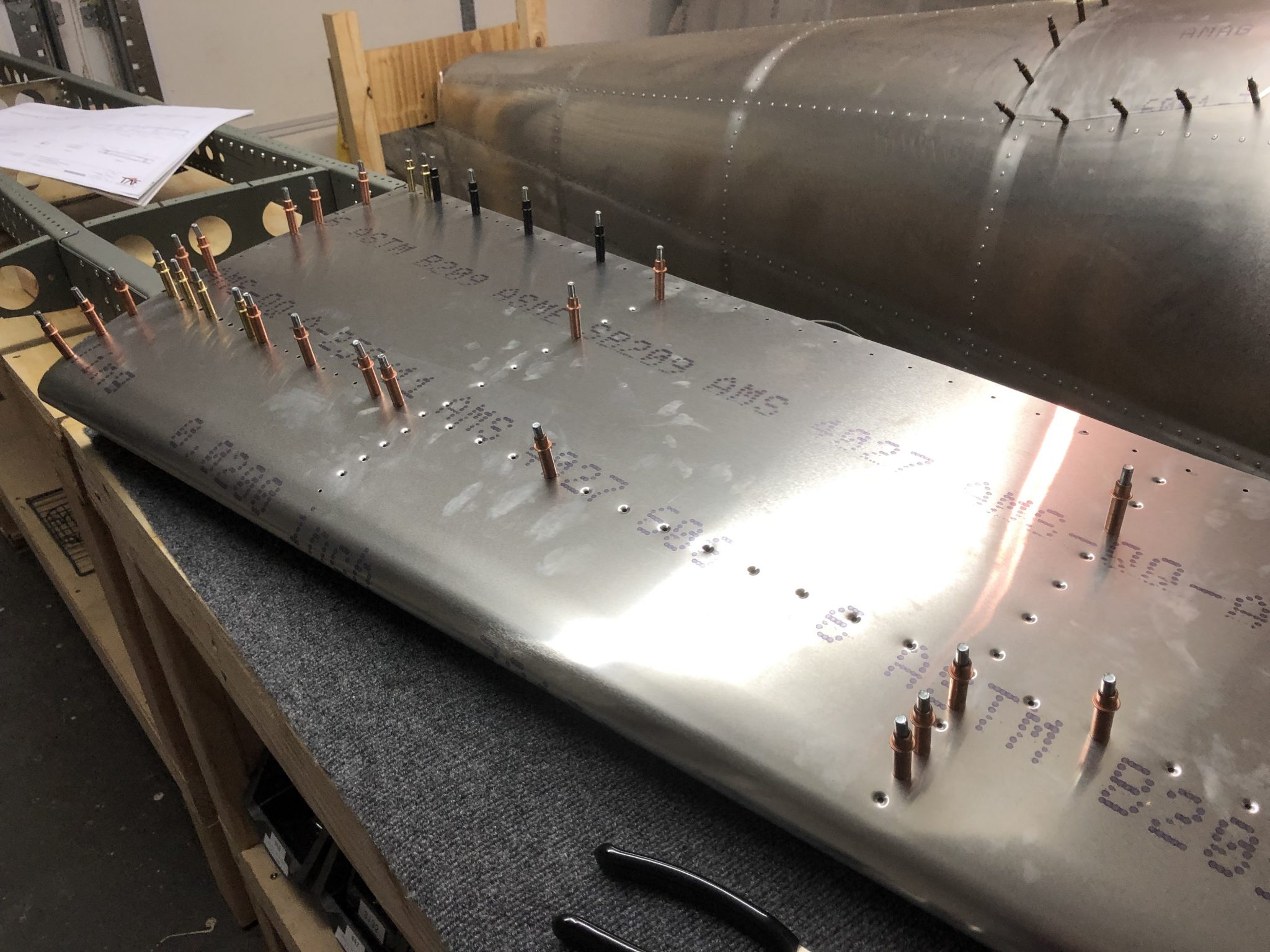
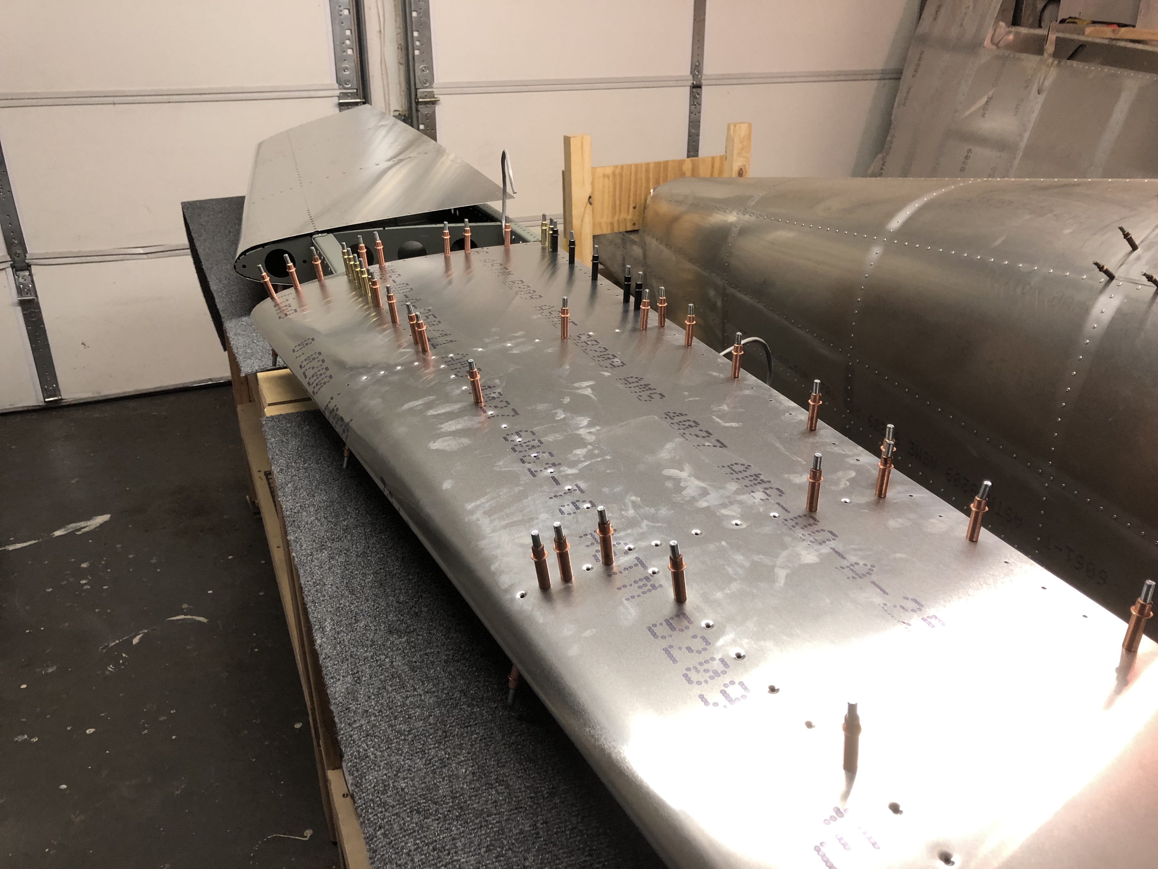
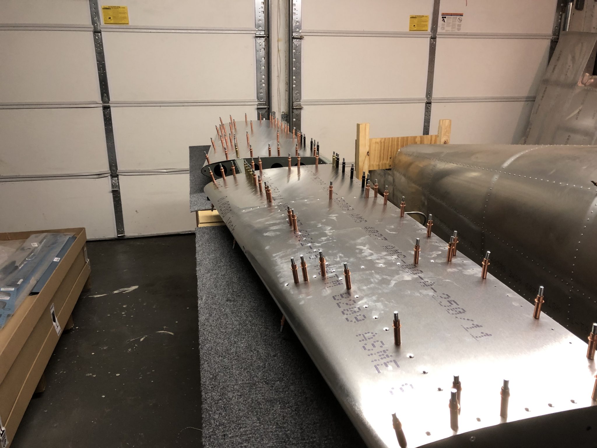
Today I was working on fitting the skin onto the Horizontal Stabilizer. It took a lot of clecos to align everything, but eventually it all came together well on both sides. The next step will be to match-drill up the dimpled holes as per the instructions.

The design for the dimples is such that the holes are drilled slightly smaller than the final size. Then they get dimpled and then you assemble everything to fit it together and finally match-drill up the dimpled holes to the final size.

Clecoing the left side of the Horizontal Stabilizer Finished clecoing the left side of the Horizontal Stabilizer Finished clecoing both sides of the Horizontal Stabilizer

I will post another timelapse video of the whole process once I’m done with the drilling and riveting.

Countersinking experiment

Why it’s important to use a 120 degree countersink pilot for pull rivets

Another thing I recently did was do a small experiment to showcase the reason to use the correct 120 degree countersinking pilot for the countersinking holes that are not dimpled due to the thickness or type of the part (such as the fiberglass tips), after we had a thread about dimpling and countersinking it on the Sling Builders discussion group.
Normal AN style solid aviation rivets are 100 degrees, so most countersinking tools sold by aviation tool supplies by default come with 100 degree countersinking pilots, but blind pull rivets like those used in the Sling are 120 degree, so hence the need to use a 120 degree pilot to get the best fit.

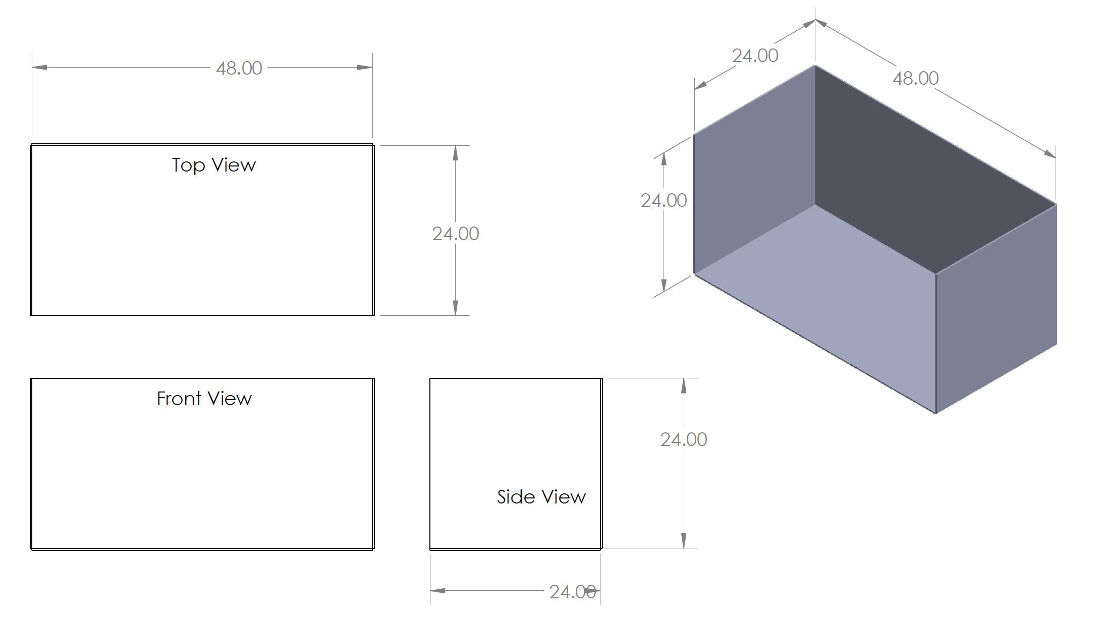
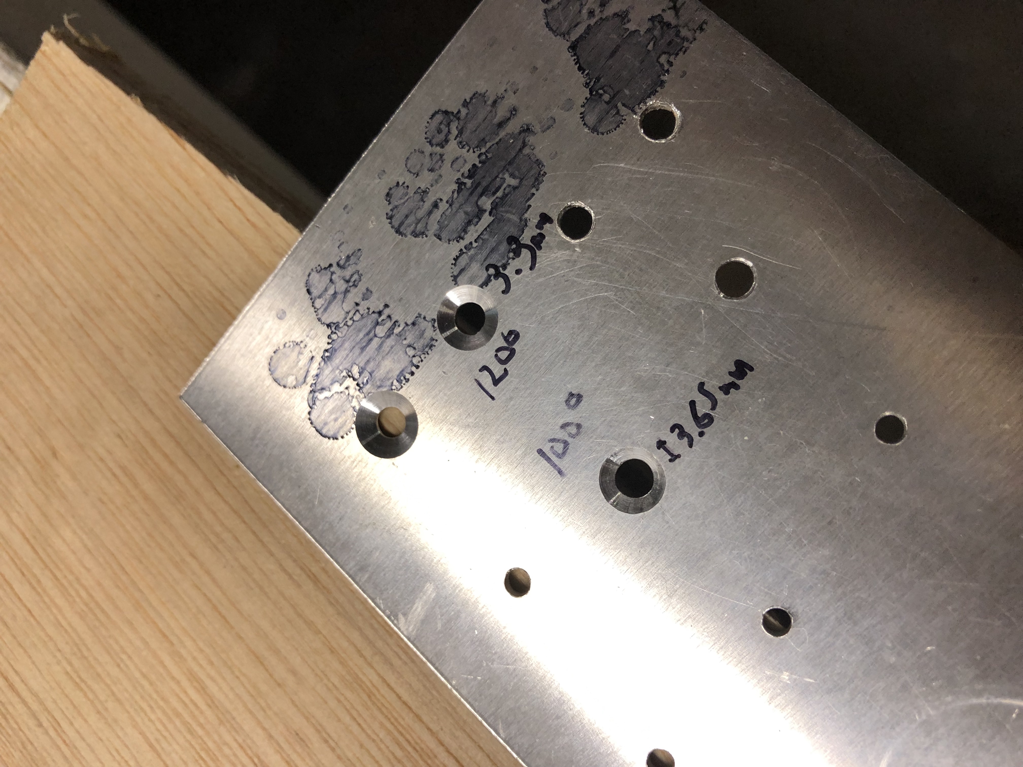
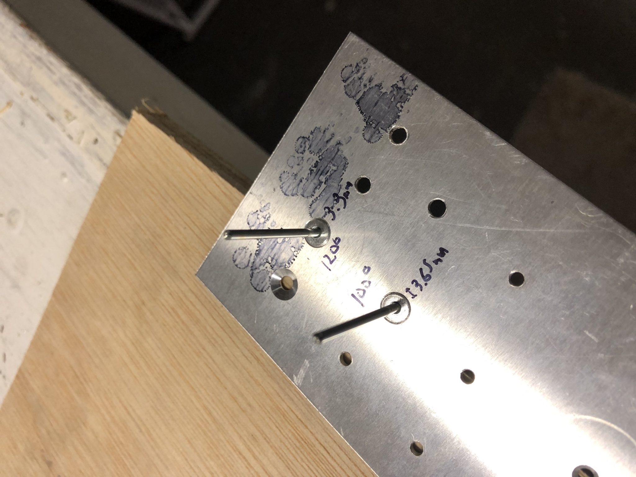
To showcase the why that is so important, I drilled some holes in a 0.04 inch piece of metal (which is the thickness where you start to countersink instead of dimple) and used the 100 degree pilot on one hole and the 120 degree pilot on another. The goal was to insert the same countersunk rivet (which has a 120 degree slant) used for the Sling in both and have it sit flush.
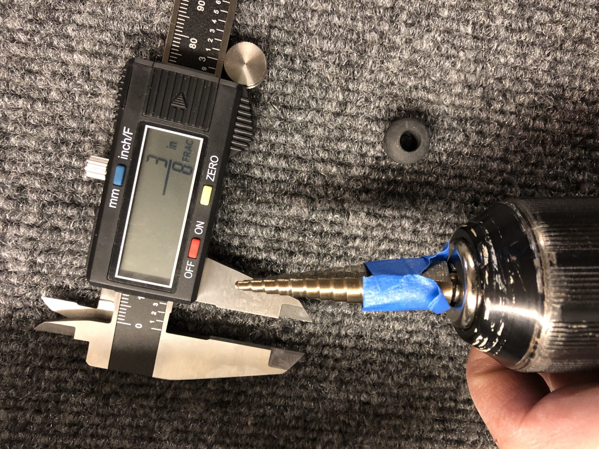
In order to get a flush fit with the metal using the rivet, the 100 degree countersunk had the be deeper. This in turn results in a larger hole and thus wouldn’t have as much material to grip onto. As can be seen below, the 120 degree countersink resulted in about 3.3 mm hole, while the 100 degree resulted in a much larger 3.65 mm hole.

Difference in hole size using 100 and 120 degree countersink Flush fit of countersunk rivet

So the moral of the story, make sure you use the correct countersinking pilot when working with pull rivets. I’ve created a separate page on drilling, rivet sizing and countersinking as a quick reference for myself and figured it might be useful for others.

Leveling the playing field

Not much progress, but I took a couple of closer looks at the tailcone of the Fuselage and ran some fishing wire through it for the VOR/LOC/GS wire from the tail.

Inside the Tailcone looking forward Inside the Tailcone looking aft

I also had an exchange with Matthew, one of the other Sling TSi builders, about the countersinking and fitment of the tips for the elevators and rudder. It looks like he is missing the reinforcement on the tips that adds material to allow the countersinking. I took some pictures of mine which shows the extra layers of fiberglass (in black) to allow enough material to countersink the tips:

Rudder and Elevator tips reinforced material for countersinking

Today is one of those few winter days with nice sunshine, so I went to the airport in the evening and did some pattern work and got a bonus moment when the Boeing Dreamlifter came in to land on the parallel runway.

Boeing Dreamlifter landing 34L at KPAE Boeing Dreamlifter landing 34L at KPAE

After getting home, I was doing some inventory and trying to figure out which part to put together next. I don’t want to close up the Rudder yet since I don’t have the light yet and want to fit that first. I got the Sealant I need to close up the Horizontal Stabilizer over the weekend, so I took that back out and put it on my workbench.

Then I got out my laser level to see if it all aligned and realized that my working surface is actually pretty slanted, so I spent some time to even out the tables. As it turns out, the garage floor has a pretty good slant as you can see below – 3 pieces of wooden shims on the far side, versus none on the near side.

Far side of the garage needed a few blocks of wood to level out the table Level table & Horizontal Stabilizer

Rudder structure riveting

Hours: 1.5

Now that I’ve prepared the Rudder parts with primer for the mating surfaces, it’s time for more riveting. I laid out all the parts and got to work assembling the Rudder structure.

Rudder parts ready for riveting Fitting the ribs of the Rudder

The strengthening plate is thicker and needed a bit more attention to deburr both the big center hole using my straight double edge deburr tool as well as the riveting holes. Most of the other holes were prepped well by the factory after checking them by running my finger over them.
The strengthening rib needed a bit of deburring

After everything looked good, I finished putting together the structure of the spar and all the ribs and lined up everything with lots of clecos.
Rudder structure laid out for riveting

And then it was time for another episode of riveting.
Riveting action Completed the riveting of the structure of the Rudder

I still have to buy the tail anti collision light that will go on top of the Rudder. I’m planning to get the Aveo Posistrobe MiniMax and then I’ll finish up putting on the skin.
Since I am planning on installing a VOR/LOC/GS antenna, I will run the wire for both the antenna, as well as the strobe light in one go through the Vertical Stabilizer as the instructions suggest.

Rudder & Horizontal Stabilizer Skin Priming

Hours: 2

I did a quick test fit of the skin on the Horizontal Stabilizer yesterday and everything looks good. I’m waiting for the sealant that goes between the Support Plate and the skin, which should arrive tomorrow. So I decided to prepare the next part of the Empennage and and prime the Rudder parts and the mating surfaces of the Horizontal Stabilizer skin.

After I did some more reading about priming preparation and I’ve slightly changed the process for the Rudder pieces. I’ll see how it turns out tomorrow once it’s dried. After removing the protective plastic, I cleaned off the parts with MEK, then scruffed them up with a red (fine) Scotch brite pad and then went on to priming.
Rudder parts laid out Rudder parts primed Horizontal Stabilizer mating surfaces primed

After the preparation, I unfolded my small paint booth I made out of some hardboard. I got the design from a video on the Family Handyman. If anyone wants to make their own and wants to skip the video, I’ve created some quick plans in Solidworks and took some pictures of the folding. What you need:

  • 2 sheets of 24 by 24 inches
  • 2 sheets of 24 by 48 inches
  • Duct tape to create the “hinges”


Lastly, I did some more organizing of the Rivets and Clecos and making use of my label maker.Rivets and Clecos organized and labelled

Horizontal Stabilizer wiring

Hours: 1

I was busy on the weekend at the Northwest Aviation Conference helping sell Raffle Tickets for the Charity Airplane Raffle that my Flying Club, Puget Sound Flyers, is holding to raffle off a refurbished Cessna 150 Airplane to fund scholarships for kids that survived cancer.

While at the conference I also briefly met up with a member of the Sling Builders Facebook group, who is considering building a Sling 2 in Sequim. We were talking all things Sling for a while and I look forward to have another Sling builder nearby soon.

I also attended some talks and got to say hi to Jason Miller, who’s a CFII and has a great YouTube channel with training tips about The Finer Points of flying.
I met Jason Miller at the NW Aviation Conference

Horizontal Stabilizer

Now back to the building part. When I riveted the ribs and spars of the Horizontal Stabilizer a few days ago, I was short a couple of the 4.0mm rivets. In order to finish the part, I took some from the Elevator hardware bag.

Today I reviewed the rest of the steps for the Horizontal Stabilizer and realized I need a whole lot more of them to actually finish riveting the Skin onto the Horizontal Stabilizer. I also need some sealant to put between the Stabilizer Plate and the skin, which I know Matthew posted on his blog when he did the part, so I re-read his post and noticed that he was actually also missing a bunch of the 4.0mm rivets, so it looks like the factory may be short when they put together that bag, I’ll let them know tomorrow.

I did finish up the wiring that will connect to the elevator trim. This gave me the chance to make use of the step drill bits I bought. I used my digital caliper to translate the metric instructions (9.5mm) to the closest fractional inches (3/8th) to enlarge some holes for the rubber grommets.
After that I installing some flexible grommet edging I bought as spare as the kit was missing that since it was shipped based on Revision 0, which didn’t include that part. I’ll have to see if there were any other parts that were added in Revision 1 after my kit was put together.

The beginning of a riveting story – Horizontal Stabilizer

Hours: 6

When we took inventory of the Empennage kit, we thought we were missing some parts of the Elevator and so I decided to start with the Horizontal Stabilizer instead, but as it turned out after double checking again, the parts were just hiding inside a channel.

Parts Prep

Laying out parts of the Horizontal Stabilizer

So after some researching I had done ahead of time, here’s the process I decided to follow for preparing the parts for priming:

  1. Removing the protective plastic
  2. Cleaning and Scrubbing the parts with Simple Green Extreme Aircraft cleaner (diluted 1 part cleaner to 2 parts water) and Scotch Brite Pads.
    Cleaning off larger pieces using Simple Green Cleaning smaller pieces in a small tub
  3. Washing off the cleaning solution with water and drying the parts
    Using some drying racks to dry off pieces
  4. Final de-greasing using MEK
    MEK to clean parts Safety Mask

Priming

After all that was done, it was time for priming, which in on itself is a whole big topic with different opinions the more people you ask. I’ve decided to prime the mating surfaces and while at first I was thinking of using NAPA 7220, ended up using Rustoleum Self Etching Primer after I saw that Matthew seems to have good results with it and it’s easier to find in the local hardware store.
Priming Horizontal Stabilizer Parts

Riveting

Since my kit was shipped out before the newer revision for the Empennage kit was finished, the printed copy only had the basic CAD drawings, but no instructions, so it’s a matter of combining the larger print outs with the instructions using my small laptop.Reading instructions from the plans

Also seen above is the Rivet Gun I’m using – it’s the Milwaukee M12 Rivet gun, which fits in nicely with all my other tools and allows me to build the airplane without the need for a noisy compressor.

Laying it out with lots of Clecos

After I put together everything with Clecos it was time to pull rivets.

Rivets Rivets pulled Juliana helped and pull her first rivet as well Pulling Rivets

And here’s the riveted structure (minus the skin) of the Horizontal Stabilizer:Horizontal Stabilizer riveted

I’m also trying to record my progress with some timelapses, so here it goes:

Airplane Kit Arrival Day!

Hours: 6

My Sling TSi airplane kit has finally made its way to my garage and arrived yesterday from The Airplane Factory in South Africa. Since I ordered the entire kit in one go as a quick build, it was shipped in one large 20 foot container directly to my house. The container arrived about two weeks ago in the port, but then the Seattle Snowpocalypse happened and we had the heaviest snow in February for over 70 years. The Seattle area is very hilly and so the sudden large amounts of snow and the hills made for impossible driving conditions and so while I couldn’t get a truck to deliver the airplane, instead we went skiing on our road sometime last week since our hill has a pretty steep incline.
It's not every day you can ski on your own street

Luckily it stopped snowing by Tuesday and warmed a bit and the City managed to start plowing neighborhoods and we could drive again by Thursday, so I called the Freight company and told them they can now give it a shot to deliver and the scheduled the delivery for Monday, which worked out great.

Unloading an airplane from a container

I set up my GoPro to try to capture the unloading process, it worked out fairly well to capture everything, so here it goes:

If this wasn’t enough, then here’s the complete story:

The Truck with the 20 foot container arrived just as my friends, who graciously were on standby the past two weeks to help, were arriving to help me unload and we went to work. The first order of business was to figure out the order to unload the container.
Container ready to be unloaded

Happy Airplane unloading crew
After taking out the big box with the Finishing kit on the side, we juggled around a bit to see if we could take the boxes on the bottom out, but they were blocked by the Fuselage Tail support, so we figured that we should take out the Fuselage next.
The wood that the Factory used to build the framing is of some impressive quality and the heavy screws driven into them were very tight, so it took some loosening by hand before even my impact driver could undo the screws, so I grabbed my trusty Milwaukee M12 Hackzall and made due process so we could get on with unloading and then undo the rest of the structure later. That and heavy use of my Utility Knife to cut through the many support straps that held down the structure.

After we got the Fuselage out, it was time for the boxes that were stored under the Fuselage, followed by the Wings.
Unloading the right Wing Wings in their happy hammock

After all that was said and done, we took down the rest of the wood framing in the container so the container was truly empty in the end:
Container unloaded and wooden frames taken down

We moved the boxes into our basement multi function room, next to our LEGO collection – building your own airplane is kind of like LEGO right?

Boxes of Airplane parts stored next to our LEGO
And the Fuselage and Wings found their home in the Garage on one side, leaving me with the other side as work space, plus I can easily move the wings around since I have wheels on the wing rack.

Fuselage and Wings stored in the garage

Cleaning up and taking inventory

I felt like the tail should have some extra support, so I quickly built a small stool for the tail to rest on, in addition to the existing framing that it came in, here is a quick timelapse of me cleaning up the workshop and building the stool:

Stool for the Tail to rest on: I built a stool to balance out the load of the tail

After that was done, I asked Juliana to come down to the Garage as I was pretending to fly the airplane as any reasonable person with a new toy in their garage would do:
Obligatory pretend flying in the airplane

And then we opened the Empennage box and started taking inventory so I can stop building wooden tables and stools and start building an airplane:
Taking inventory of the Empennage Kit

Now it’s time to build an airplane!