Category Archives: Empennage

Vertical Stabilizer Structure

Hours: 3

After finishing attaching the rivnuts to the rear spar parts the other day, I put everything together and did a brief test fit with the Fuselage where it attaches into. Vertical Stabilizer rear spar in place with the Fuselage

After putting together the rear spar, I also enlarged the holes in the spar so that the M4 screws can actually be screwed in and enlarged the bottom two holes so that the bottom rivnuts sit flush with the spar.
 Holes enlarged for the M4 screws and bottom two holes enlarged for flush fit of those 2 rivnuts,Screw holes enlarged and the bottom 2 rivnuts made flush with the spar

Looked all good, so onto riveting together the inner structure of the Vertical Stabilizer.Riveting the rear spar of the Vertical Stabilizer Adding the inner ribs to the rear spar Structure coming along Inner structure of the Vertical Stabilizer riveted together

I also enlarged the holes for the wiring and added snap bushings since the inside won’t be accessible once it’s closed up and the snap bushings have a better durability than rubber grommets.
Snap bushings for the wiring

There was one spot on the rear spar where one rivet was very close to one of the rivnuts and I had to use my manual hand rivet gun to pull the rivet as the head of the Milwaukee was too large to get in there.
Clearance between the rivnut and the rivet was very tight so I had to use my hand riveter instead

Completed inner structure of the Vertical Stabilizer:Completed structure of the Vertical Stabilizer


Lots of Rivnuts on the Vertical Stabilizer

Hours: 1.5

After putting the Elevator construction on pause due to the alignment issue of the center rib. I decided to get started on putting together the Vertical Stabilizer. I’ve heard back from the Factory and it turns out that they’ve changed the Rib and will be sending me the correct new versions of the ribs (EL-RIB-001-C-E-1 & EL-RIB-101-C-E-1), so I’ll have to wait until I get those.

So onto the Vertical Stabilizer – the bottom of the rear spar holds a lot of M4 Rivnuts, so it was time to updrill the holes to the correct size in order to fit the rivnuts.Getting my tools ready to install the rivnuts

Using the step-drill bit I enlarged the holes just a bit smaller than the Rivnuts and then finalized it to the exact size using a hand reamer since you don’t want the hole to be any larger than the not so it gets a tight fit.
Hand reamer marked to the correct size using masking tape Test fitting Rivnuts after reaming them to the correct size

Once I was done enlarging all the holes I took care of deburring the holes and then went to work installing all the rivnuts using the Astro ADN14 Rivnut puller attachment for my drill and adding Loctite 277 (red) Threadlocker for added strength.Before deburring the holes after I enlarged them Tools ready to install the rivnuts Rivnuts installed using my bench vise to hold the bracket in place Done installing all the rivnuts

After all that was done, I put together the spar with the brackets for a quick test fit. While doing so I also found an error in the instructions, which say to rivet the hinges on the bottom with 8 (4 a side) 4mm rivets, but actually, only the center one (where I have black clecos) should be riveted, the outer ones will be bolted to the Fuselage (which is why they have larger holes already and I temporarily used the larger golden clecos to hold it in place), so I sent the Factory a note to correct the instructions.
Vertical Stabilizer Rear spar with brackets clecoed in place

More Elevator priming & assembling center spar structure

Hours: 5

With the weather warming up, I got to spend some time sitting in a bit of sun with the garage door open and preparing, deburring, cleaning and then priming more parts of the Elevator.

Laying out and preparing Elevator parts Primed Elevator parts

Assembling Elevator center spar

The first thing I put together was the Center Spar itself, which I had primed already together with the counterweight the other day. Setting everything up was pretty straight forward as usual and while I was working on it I had a visit from another builder of the EAA chapter I’m part of who actually happens to live very close by and is building an RV. And then another friend was visiting and I happened to have some rivets ready to be riveted, so I continue my new tradition to have guests pull a rivet on the plane and sign it.

Elevator Center Spar Elevator Center Spar riveted

Assembling the center structure to the spar

After the priming from yesterday had some time to dry and set, I went to work to put together the center rib assembly with the center spar. There are a lot of pieces that slot together in there, so it took some time to figure out what slots into which piece. for the center channel to go on:
Center Channel in place

Unfortunately I encountered a problem with the alignment of the holes on the center Rib, both left and right, with the plate as seen below:
Rib holes misaligned with the center plate Closeup of the misalignment of the elevator rib

In trying to figure out which piece is wrong, I started putting together more of the structure temporarily with clecos and the strange thing is that the other holes on the ribs are aligned fine (the black clecos below), so then I thought that it must be the top center plate.

More of the Elevator center structure in place

But then I took off the center plate to check its alignment with the outer skin and there the holes of the top center plate align correctly with the holes on the skin. So this in turn then lead me back to determining that the top (and bottom) holes on the Rib 1 must be the culprit.

It is very strange since the misalignment is pretty severe. It definitely doesn’t look like this could just be resolved by up-drilling the holes, so I sent a note to the factory to ask how to proceed. My guess is going to be that I need new center ribs.


Elevator priming & counterweight riveting

Hours: 4

While I was waiting for some parts to complete the ribs for the Vertical Stabilizer, I got started working on the Elevator. Since there are a lot of parts to the Elevator I broke it down into smaller tasks, first preparing the parts of the center counterweight and then I’ll continue next with the other parts of the structures.

So onto another session of preparing the parts, deburring holes and edges and cleaning with Simple Green & degrease with MEK. After that was all done it was back into my small paint booth to prime everything.
Cleaning Station in action Cleaning the Elevator parts with Simple Green Priming the counterweight parts Priming some of the Elevator channels Priming some of the Elevator parts

Riveting the Elevator Counterweight

After all that had time to cure for a day I went to work to put together the center counter balance weight support (that’s a mouthful).
I found a small error in the instructions that say that there are 14 rivets in the center, but it’s actually 16 rivets. Sometimes with these small errors I wonder if they are intentional to keep us builders on our feet to make sure we “measure twice and drill once” – I sent the Factory a note to correct the error in the instructions for the next iteration.

So after I laid out all the parts I put everything together using clecos and the two AN3 bolts and then went to work riveting it together. A friend was visiting from Ireland as well, so after a tour of the garage and everything he also pulled his first rivet and I had him sign his name under it.Parts of the Elevator Center Counter Balance Weight Support laid out Everything clecoed together Done riveting the Center Counter Balance Weight Done Riveting the Center Counter Balance Weight

Rudder Timelapse video

I also recently finished editing together the work on the Rudder, so here’s the completed Timelapse video:

Vertical Stabilizer Navigation Antenna Mount

Hours: 1.5

Now that the Rudder is finished, it’s on to the next few tasks. I received the reinforcement plate for the Rami AV-525 Navigation Antenna to go onto the Vertical Stabilizer, so I had everything to get that fit in place.

First I did a bit of test placements and confirming the correct alignments with the plans. Then I marked the hole that needed to be enlarged and the part of the opening on the opposite that needs to be trimmed back.
Reinforcement plate for the NAV antenna to mount into the Vertical Stabilizer Rib Test placing the Antenna on top Test placing the Antenna on top Hole marked for enlarging Area marked to be trimmed

Once that was figured out, I got out the step-drill bit and enlarged the hole for the Antenna to fit through. Then I trimmed back some of the other side for the second pole and deburred everything. Finally I put a grommet into the hole and some flexible edge protection for the other side and placed the antenna in for a test fit.

Grommet installed in the hole and side trimmed Rami AV-525 NAV Antenna in place

Rudder Anti-collision light wiring

Hours: 2

Now that the Rudder is almost complete, I needed to make the wiring for the Anti-collision light permanent. The existing wire of the Aveo Posistrobe Minimax I’m using has 4 wires (ground, power, strobe, sync), so I needed to splice those onto the wire so I could run it through the structure.

Since this is a permanent connection, I’m using Heat Shrink Solder Sleeves, which have solder in the center and when you heat it up, the solder melts and the sleeve shrinks down to create a good seal.

After that was done, I added some expandable braided Sleeving over the wire for extra protection.
Expandable Braided Sleeving for the wire

I up sized the hole for the wire to pass through the fiberglass tip using my step drill bits and then ran the wires through the structure and out the front hole, which I also had to drill up as per the instructions. After some more research, I replaced the rubber grommets with snap bushings. They last longer and for the front hole in particular, they hold on better since they snap in place.
Finalized hole size for the wiring to pass through the fiberglass tip Snap bushing for the wire to come out of instead of using rubber grommets

Here’s the light mounted and completed wiring done.Light mounted and wiring finished

Now the last thing to do is close up the top. Inspired by a discussion from a while ago on the Sling Builders group, I was contemplating the idea of making the fiberglass tip removable using nut plates and screws, but I think I’ll end up just riveting it closed.


Finishing the Rudder skin & mounting the light

Hours: 4.5

I spent some time over the past week figuring out Electrical wiring and Antennas, talking with Adam from Midwest Panel Builders who I am working with for my panel and wiring.

Aside from that I was working on finishing the Rudder and preparing for the next parts. Jean is sending me replacements for the dented ribs of the Vertical Stabilizer, so I can put that together next and the Navigation Antenna will arrive this week as well to get that going. I will be using the Rami AV-525 VOR/LOC/GS Antenna.

Riveting the skin went all pretty smoothly. I had to take off the front top skin one last time as I had a bit of overspray on the outside from priming. A little bit of scrubbing using MEK and it was all clean.

Mounting the light to the fiberglass tip

After I finished the skin, I worked on mounting the support plate I made earlier for the anti collision light on top of the fiberglass tip.
To pull the rivnuts I’m using the Astro Pneumatic ADN14 tool and Loctite 277 Threadlocker. It just mounts to the front of my drill and then you just need to hold the shell and the drill pulls in the rivnut.

After all that was done, I temporarily mounted the light onto the Rudder and ran the wire through the structure. Then I brought over my DC Power Supply unit and made it shine brightly.

Testing the light in place using my bench power supply

Rudder Tip fitting & riveting the skin

Hours: 2.5

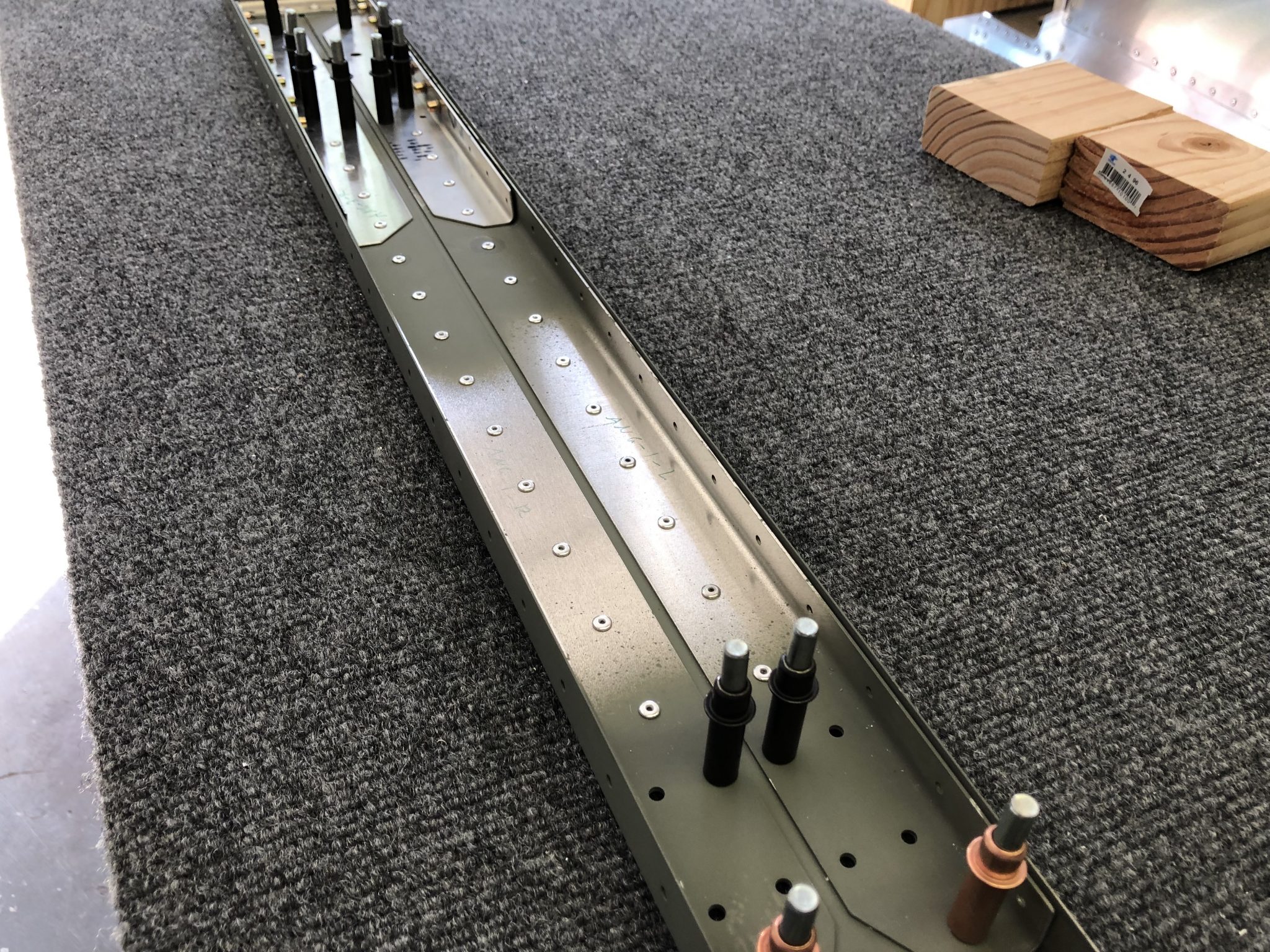
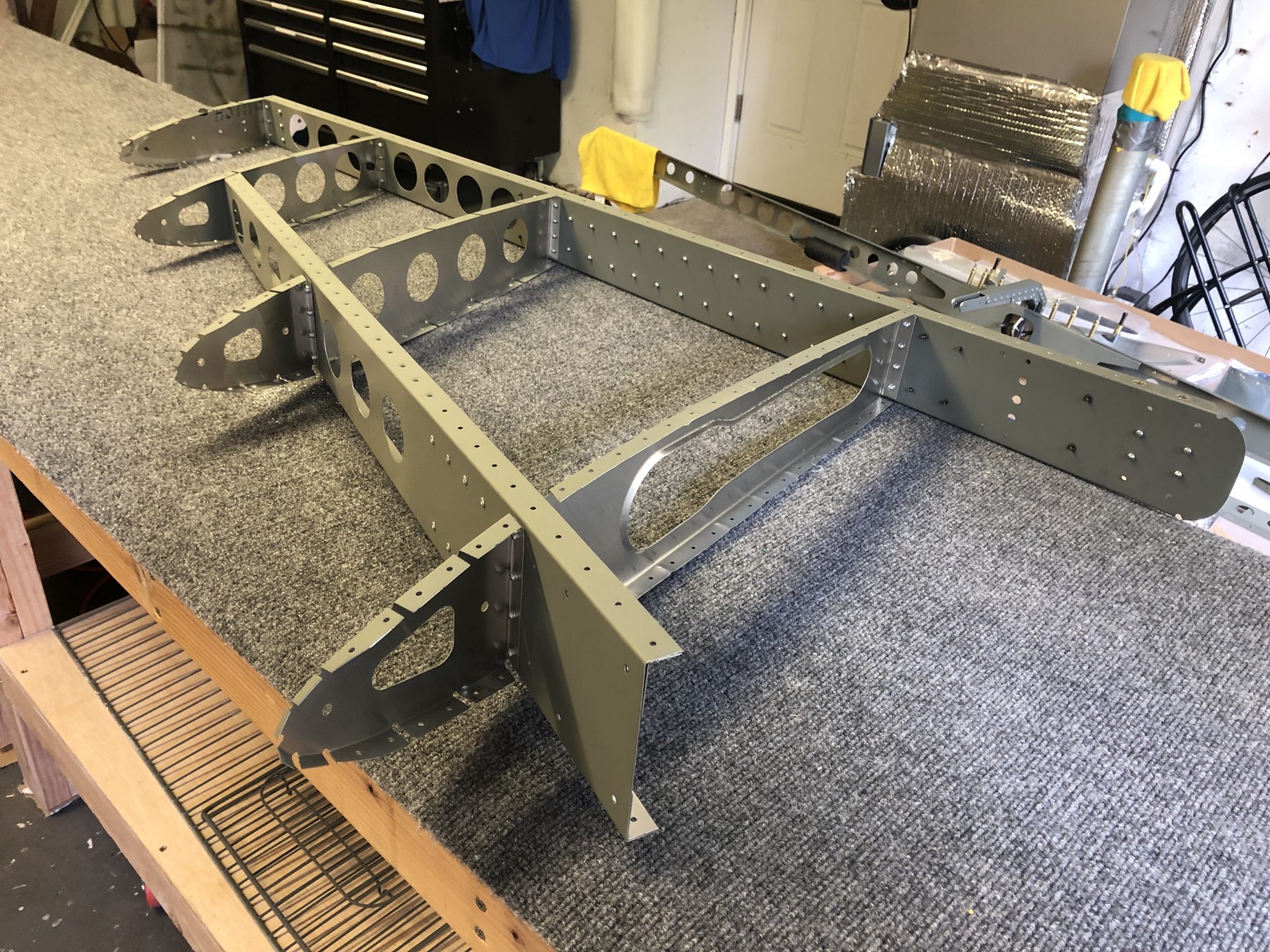
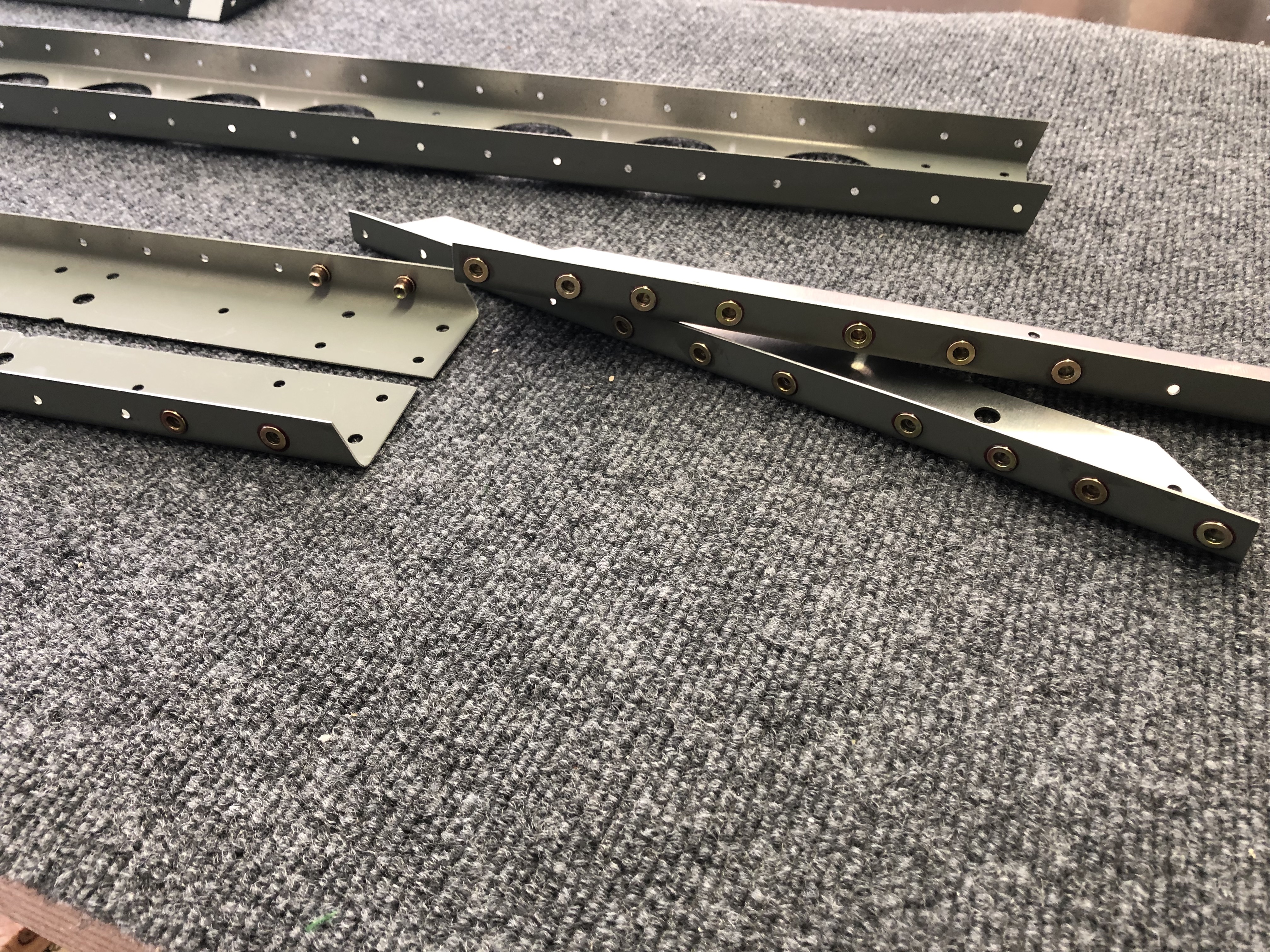
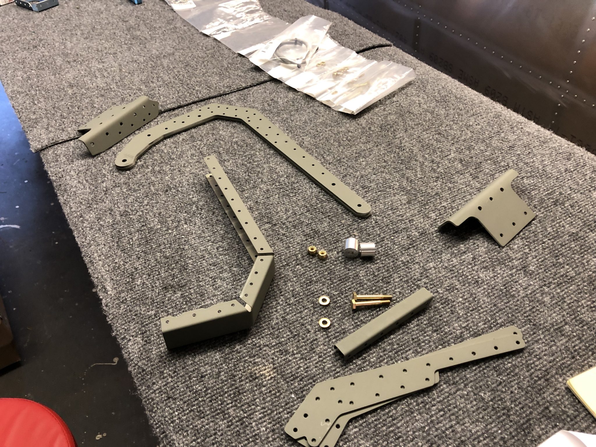
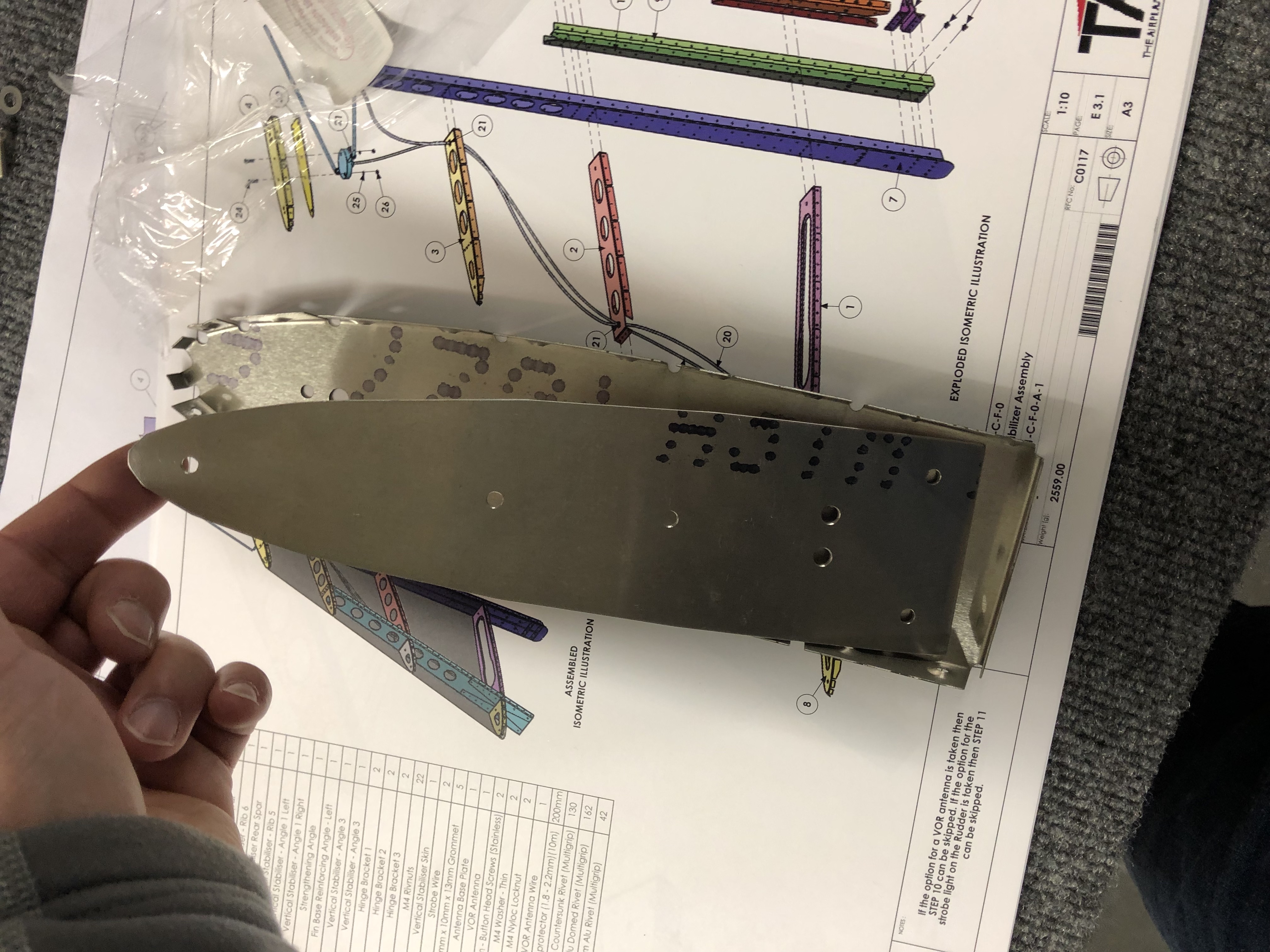
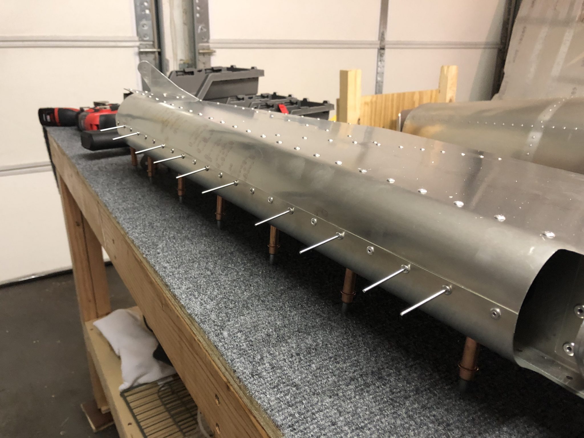
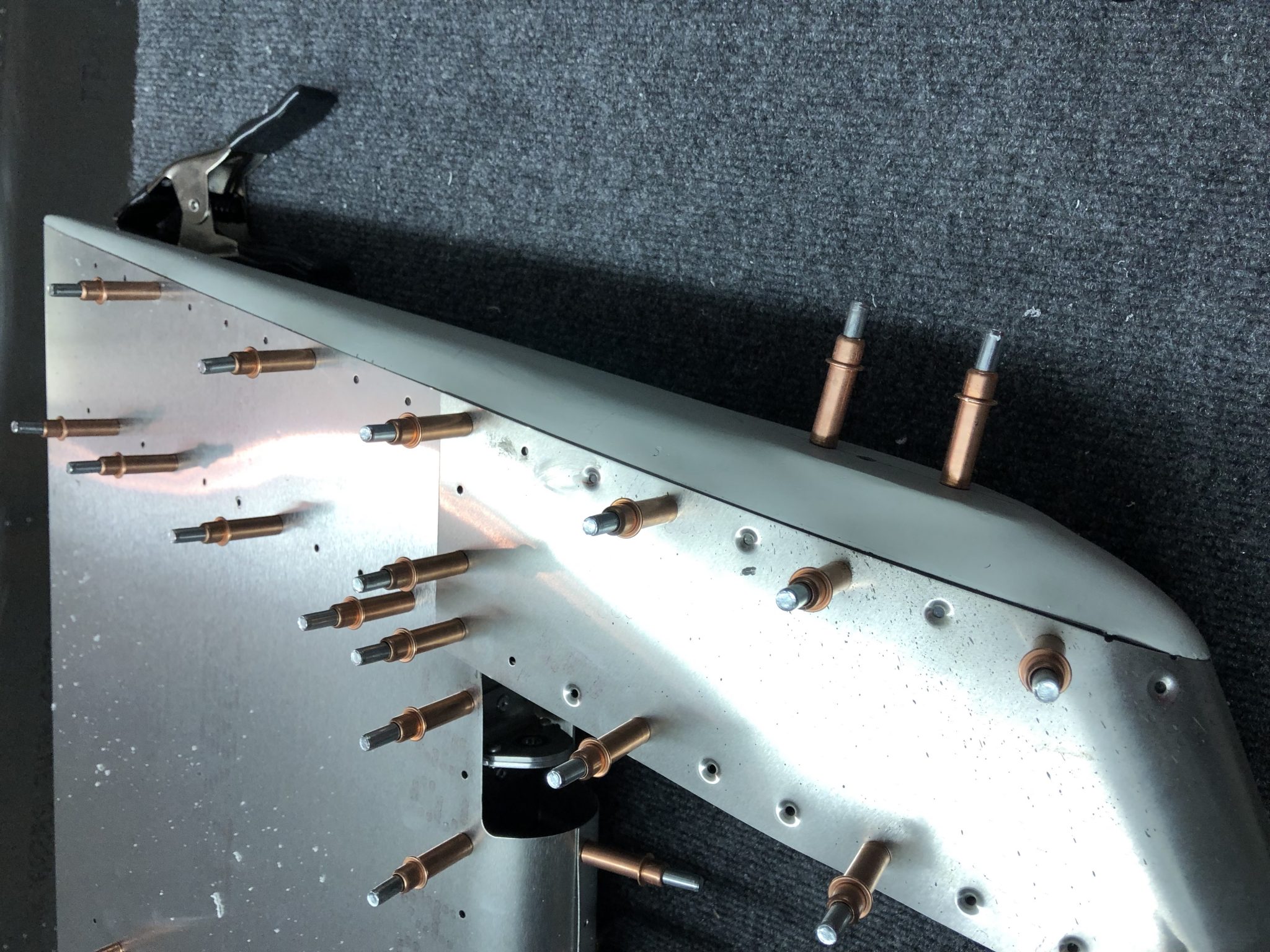
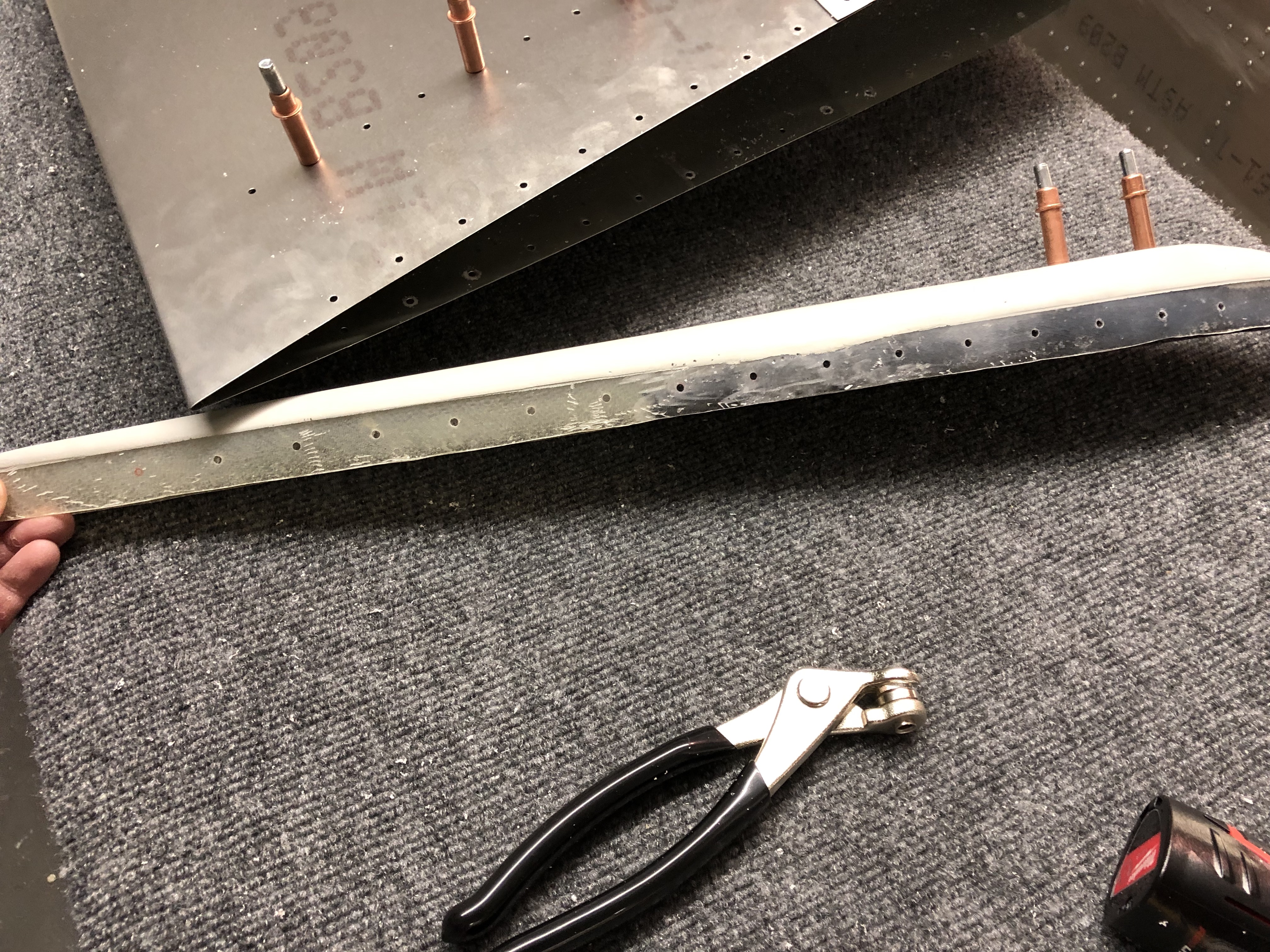
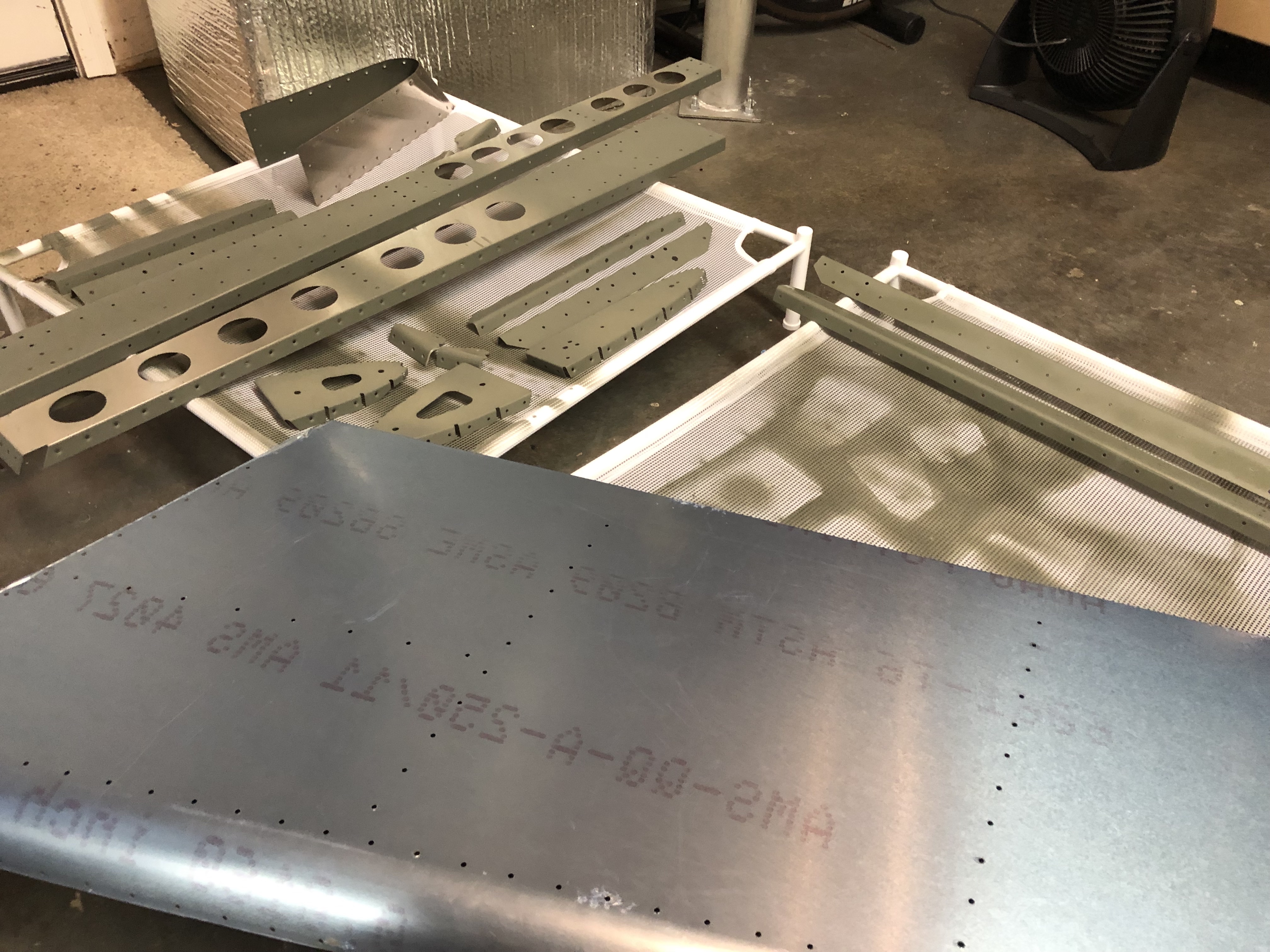
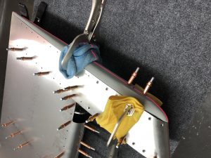
After having primed the inner surface of the Rudder skin the other day, I had all the pieces together to start working on finishing the rudder.

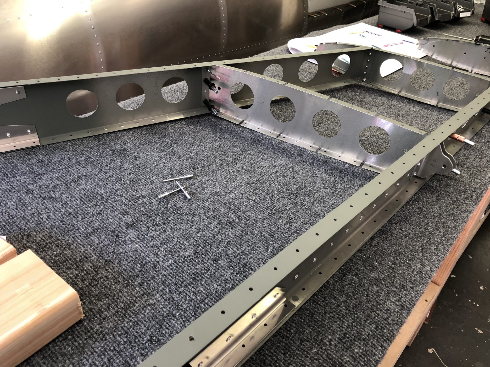
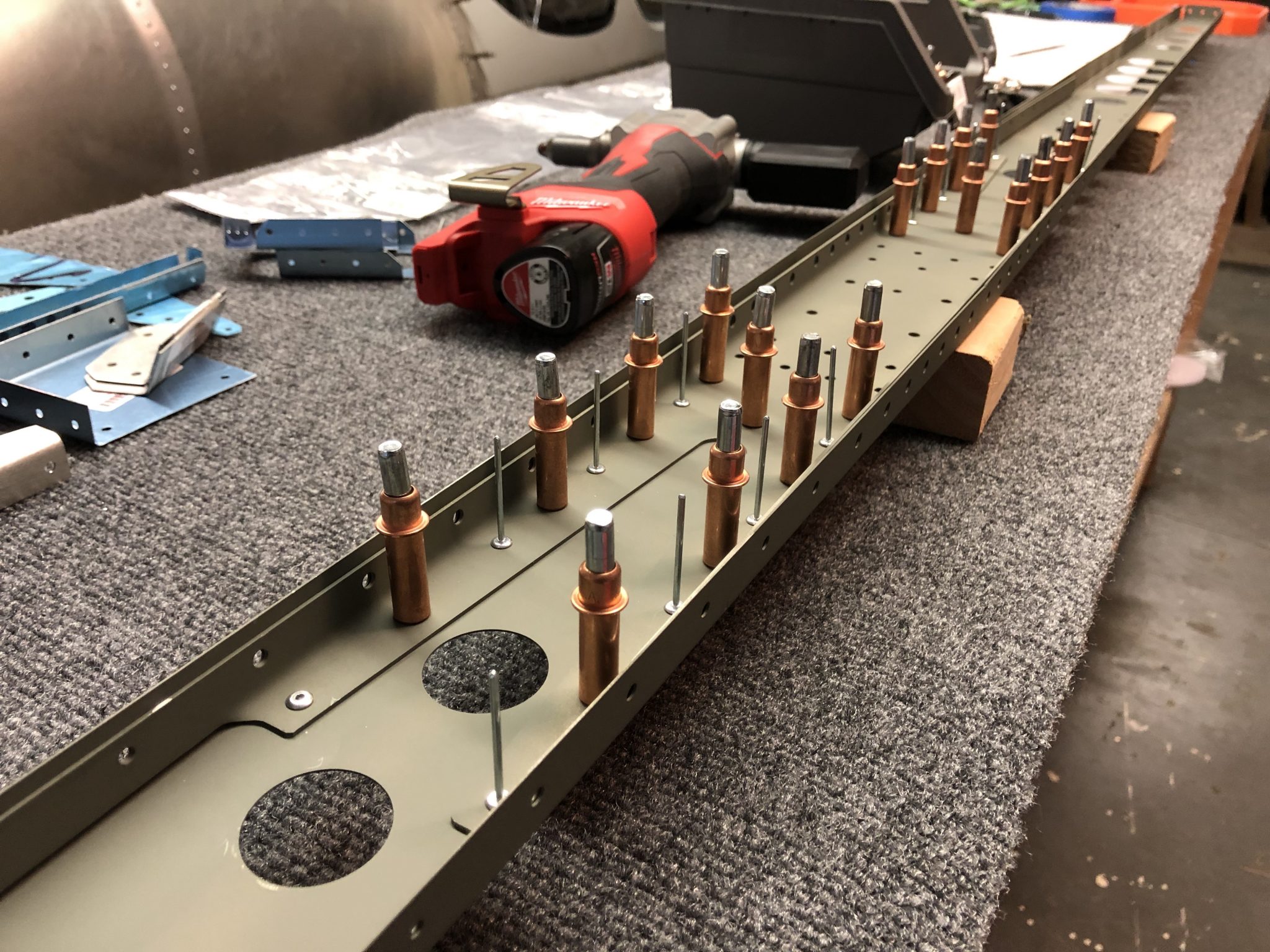
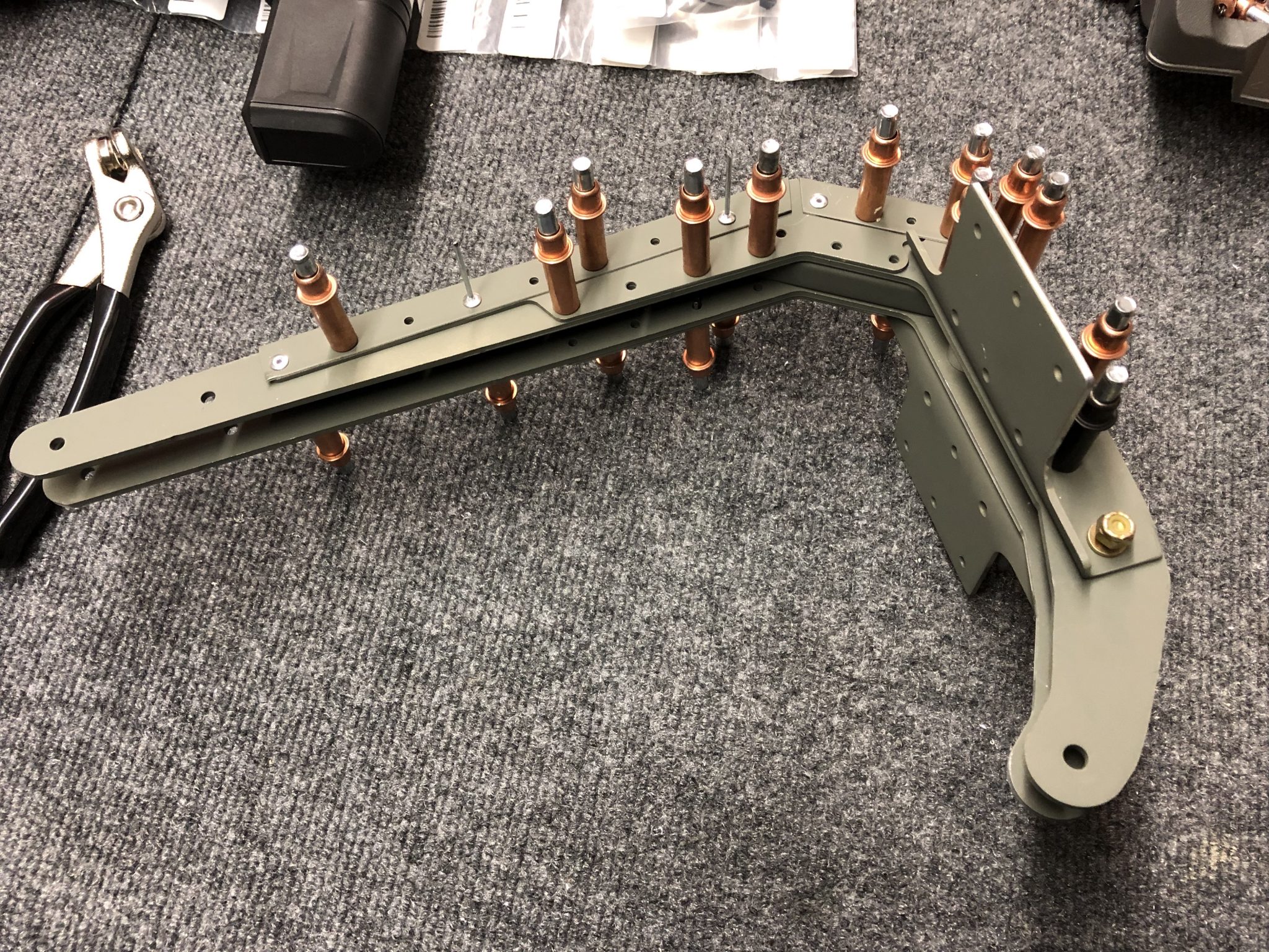
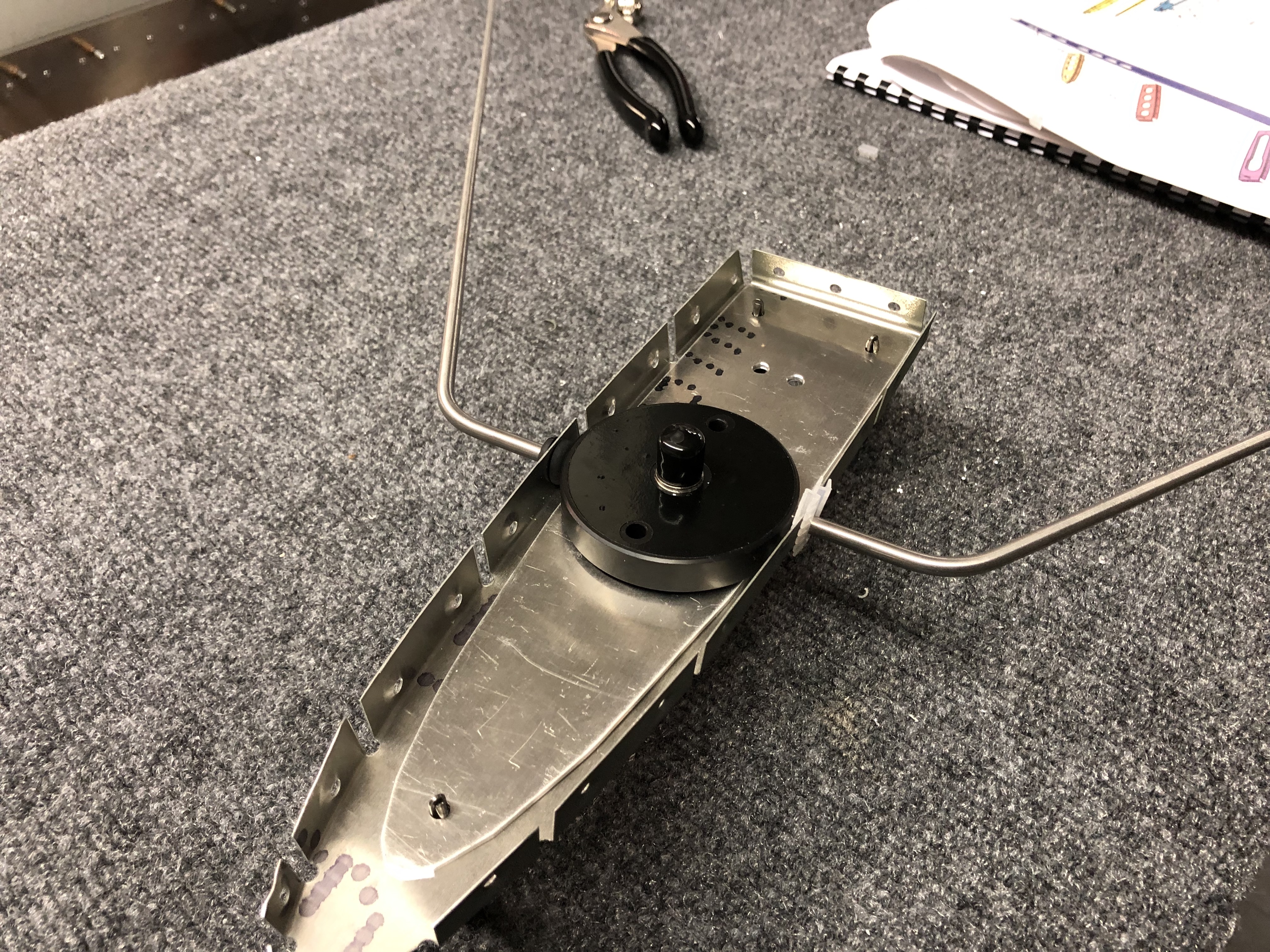
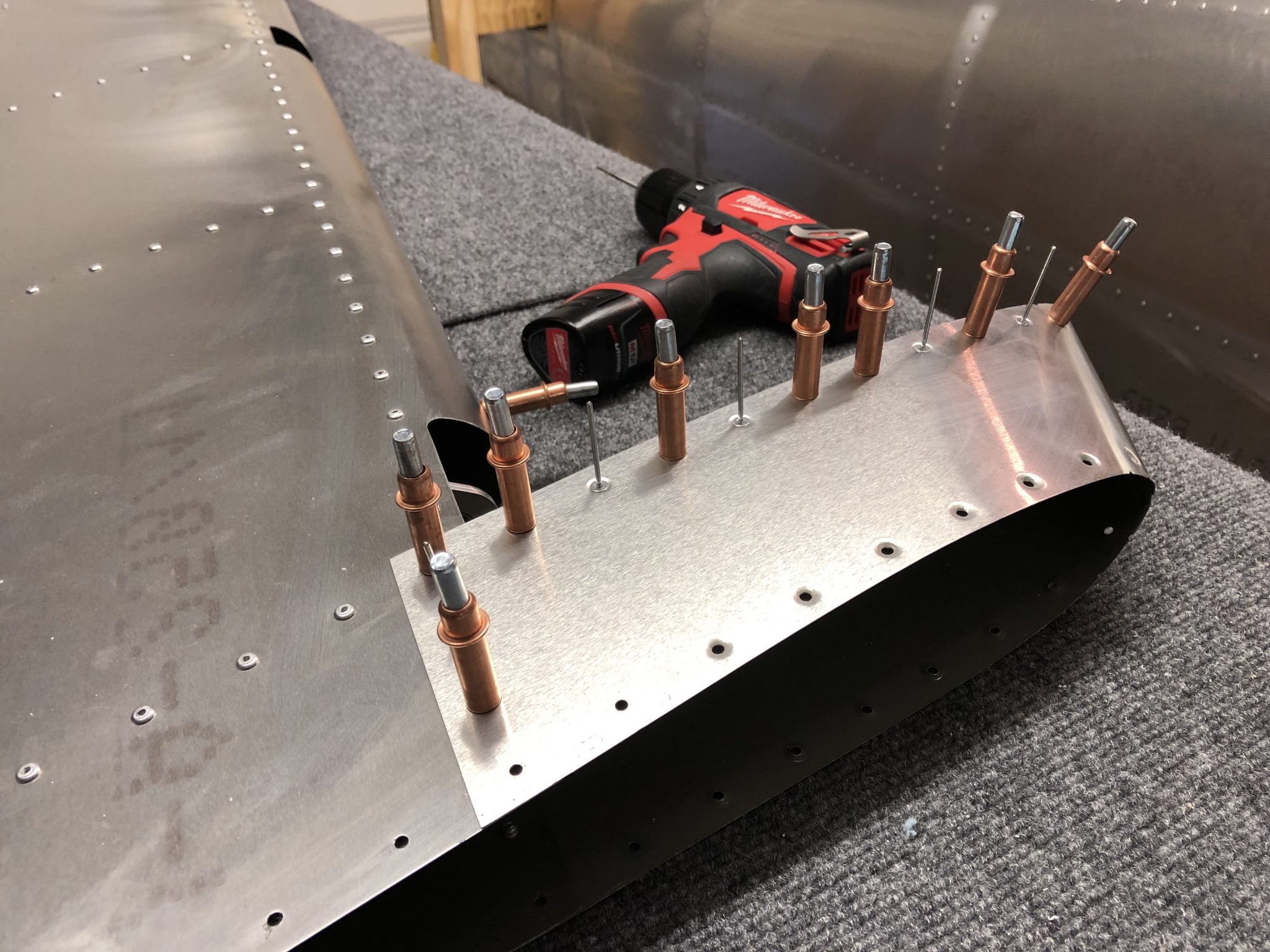
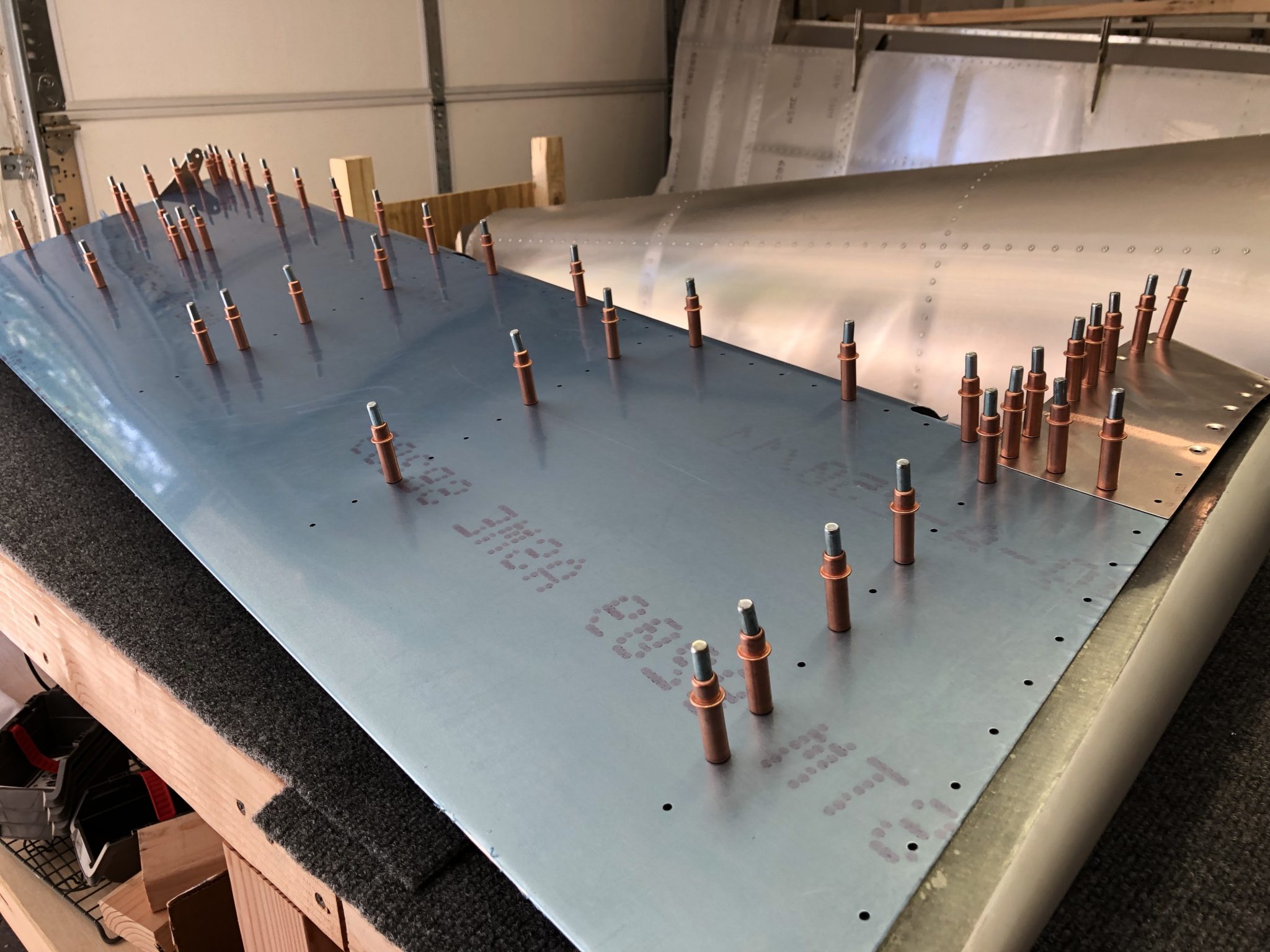
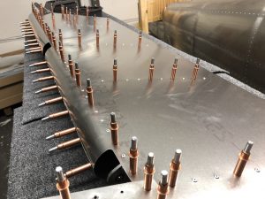
I attached the skin onto the structure and clecoed it into place.Rudder skin clecoed in place

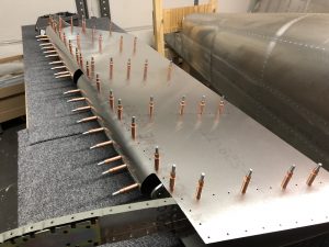
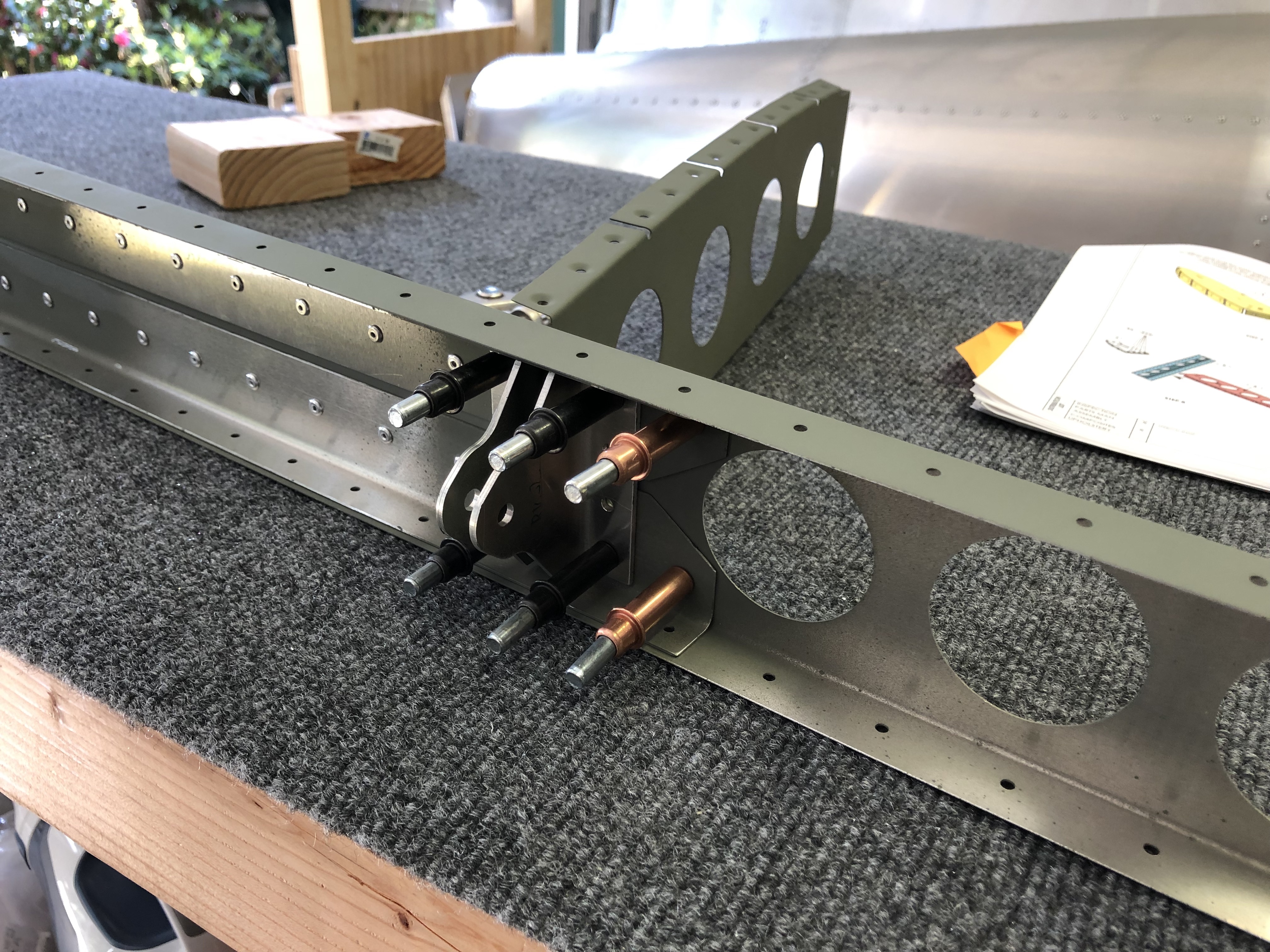
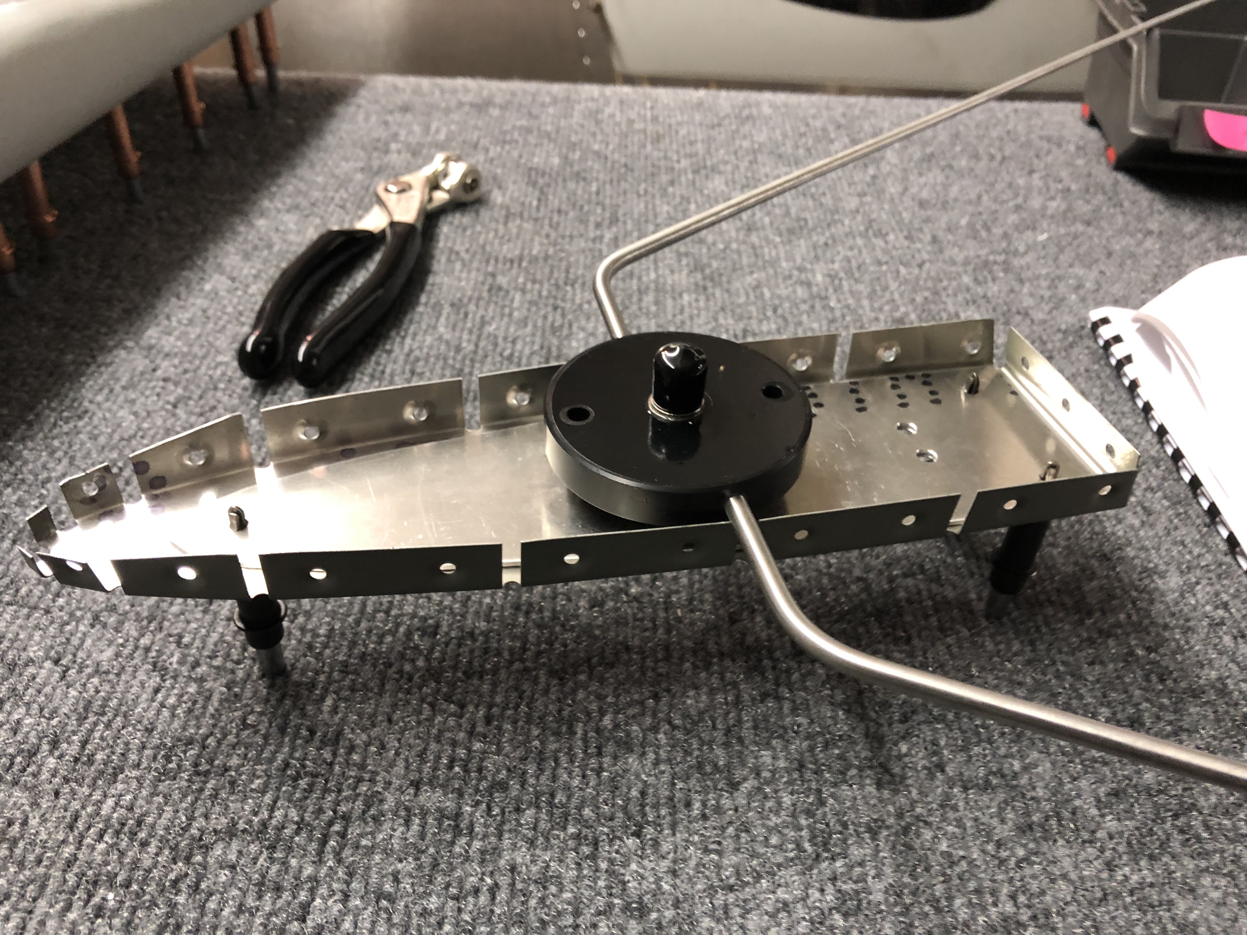
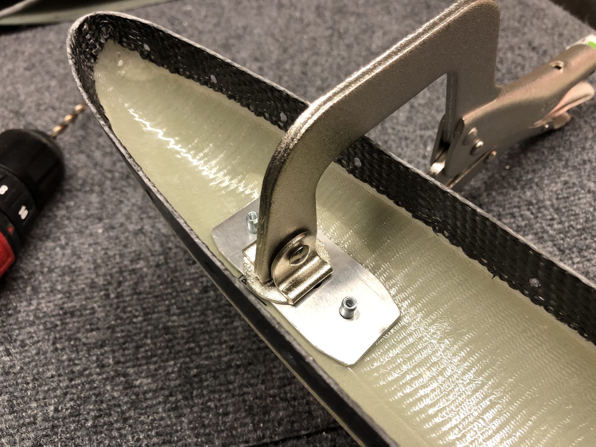
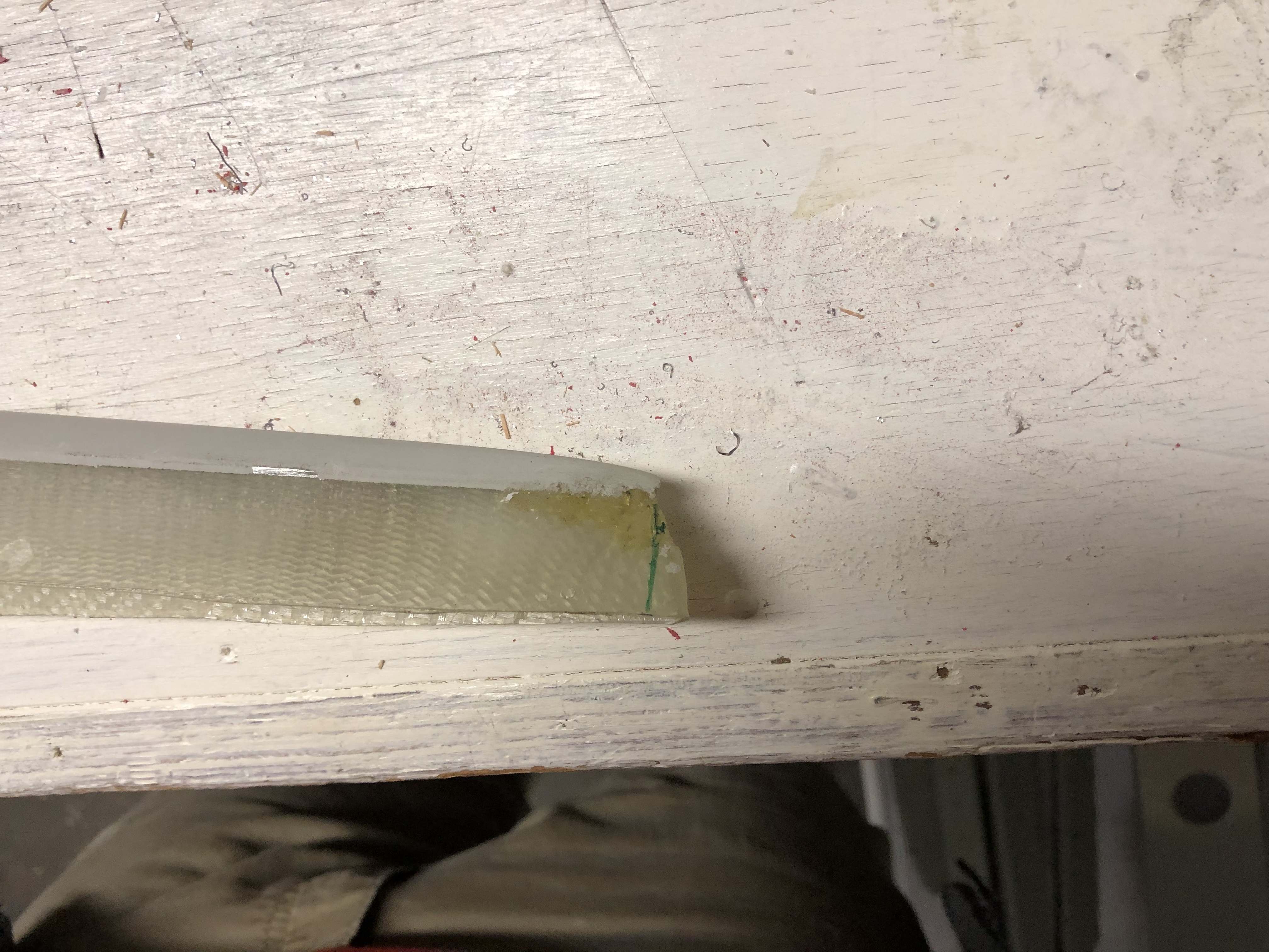
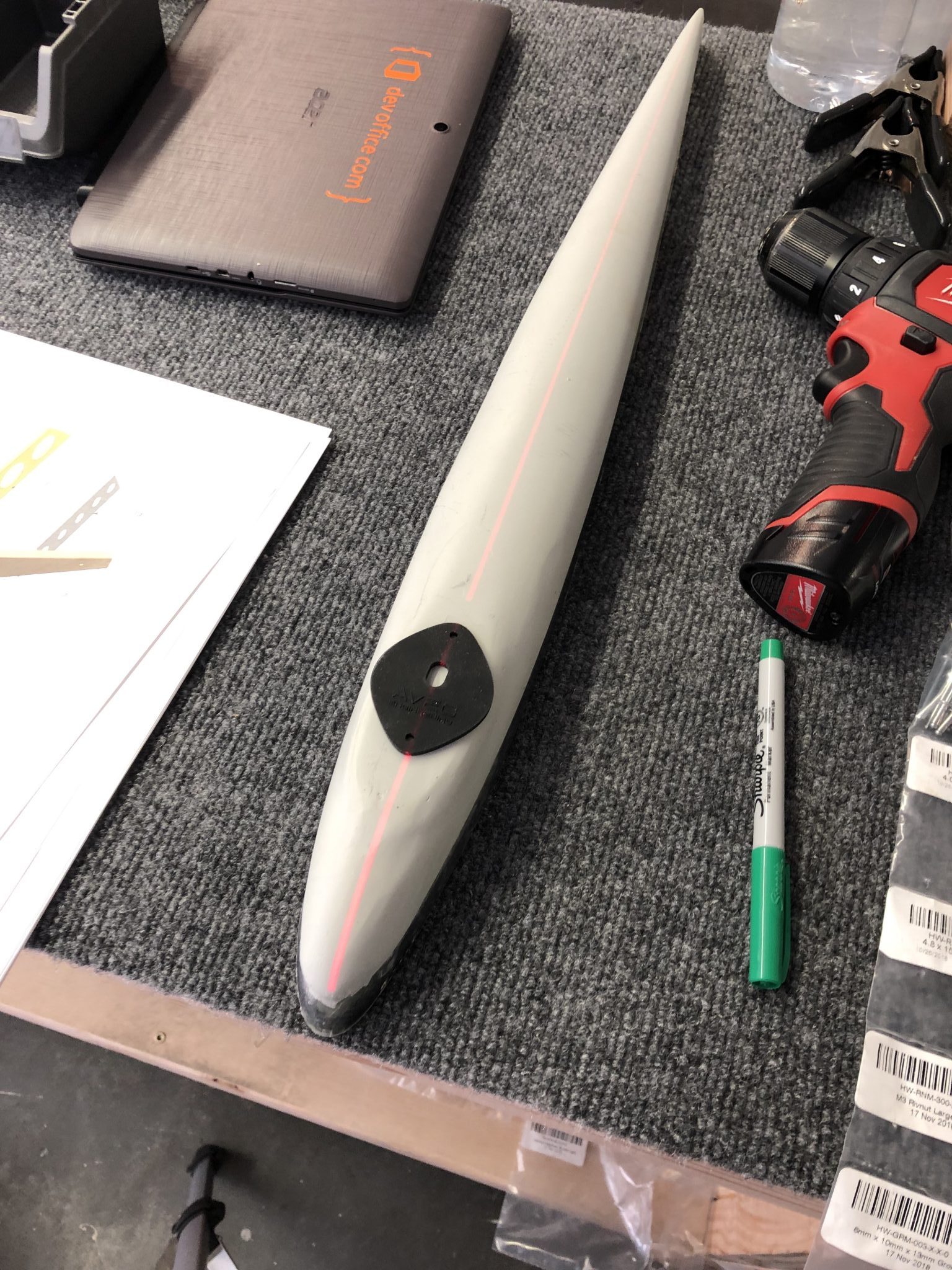
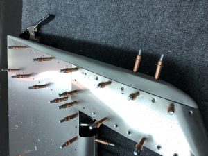
Fitting the fiberglass tip

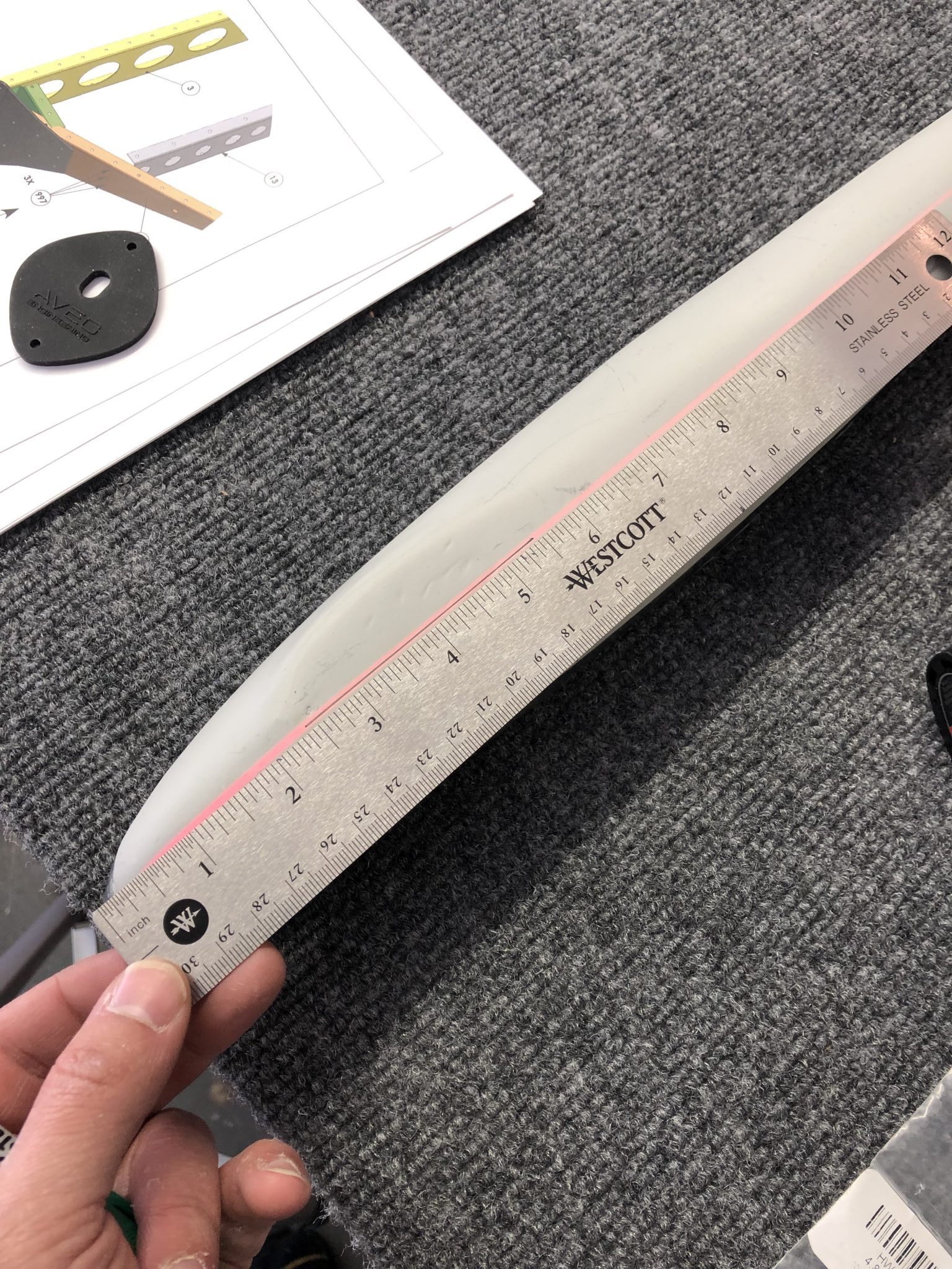
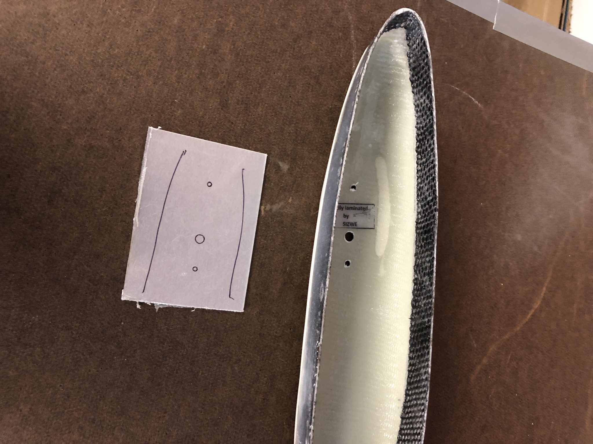
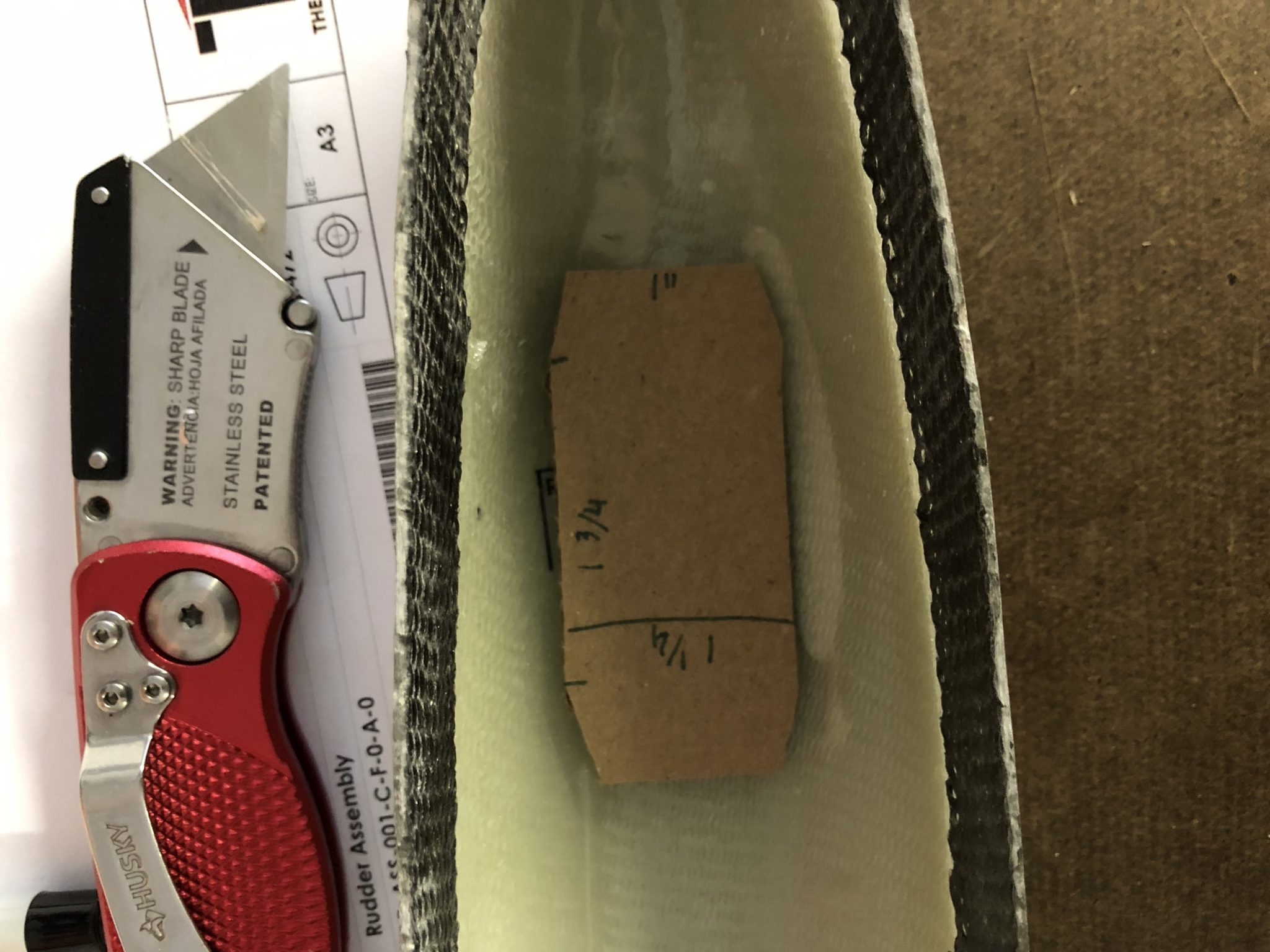
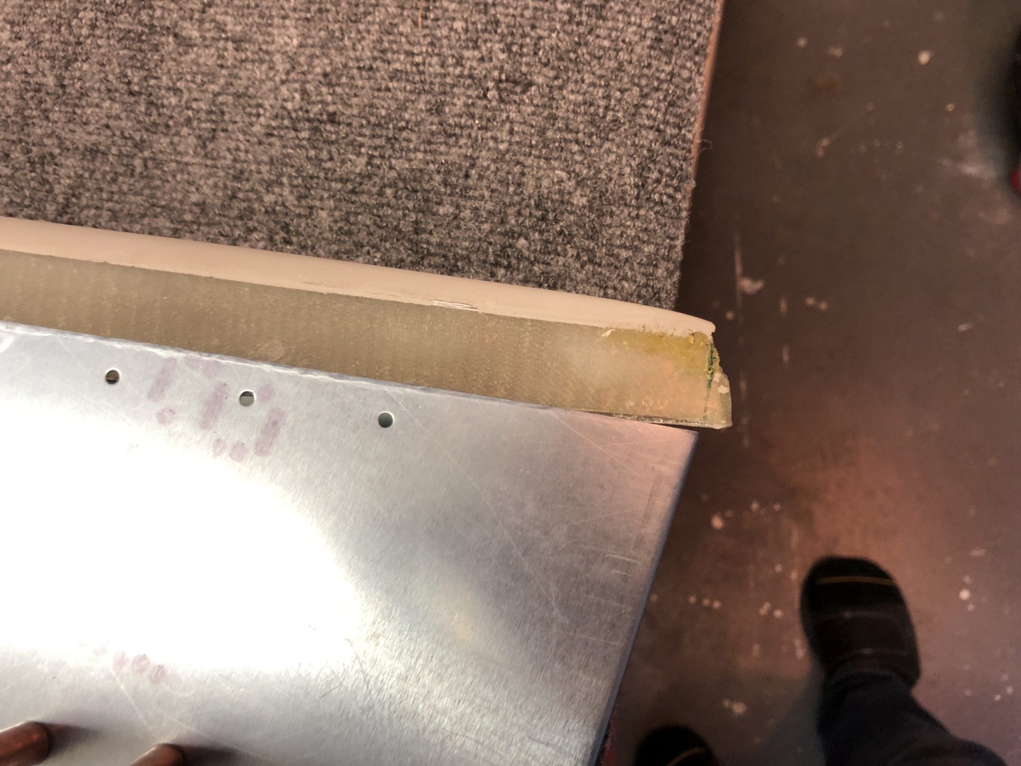
Once that was done, I went to work to fit the fiberglass tip onto the skin. I had to trim a little bit away from the bottom of the fiberglass. I made a first rough measurement, trimmed it away using my Dremel and then tried to fit it in.
First trim mark on the fiberglass tip

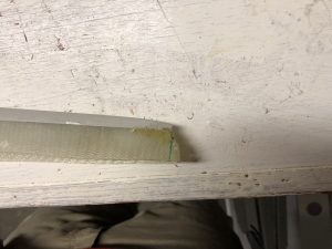
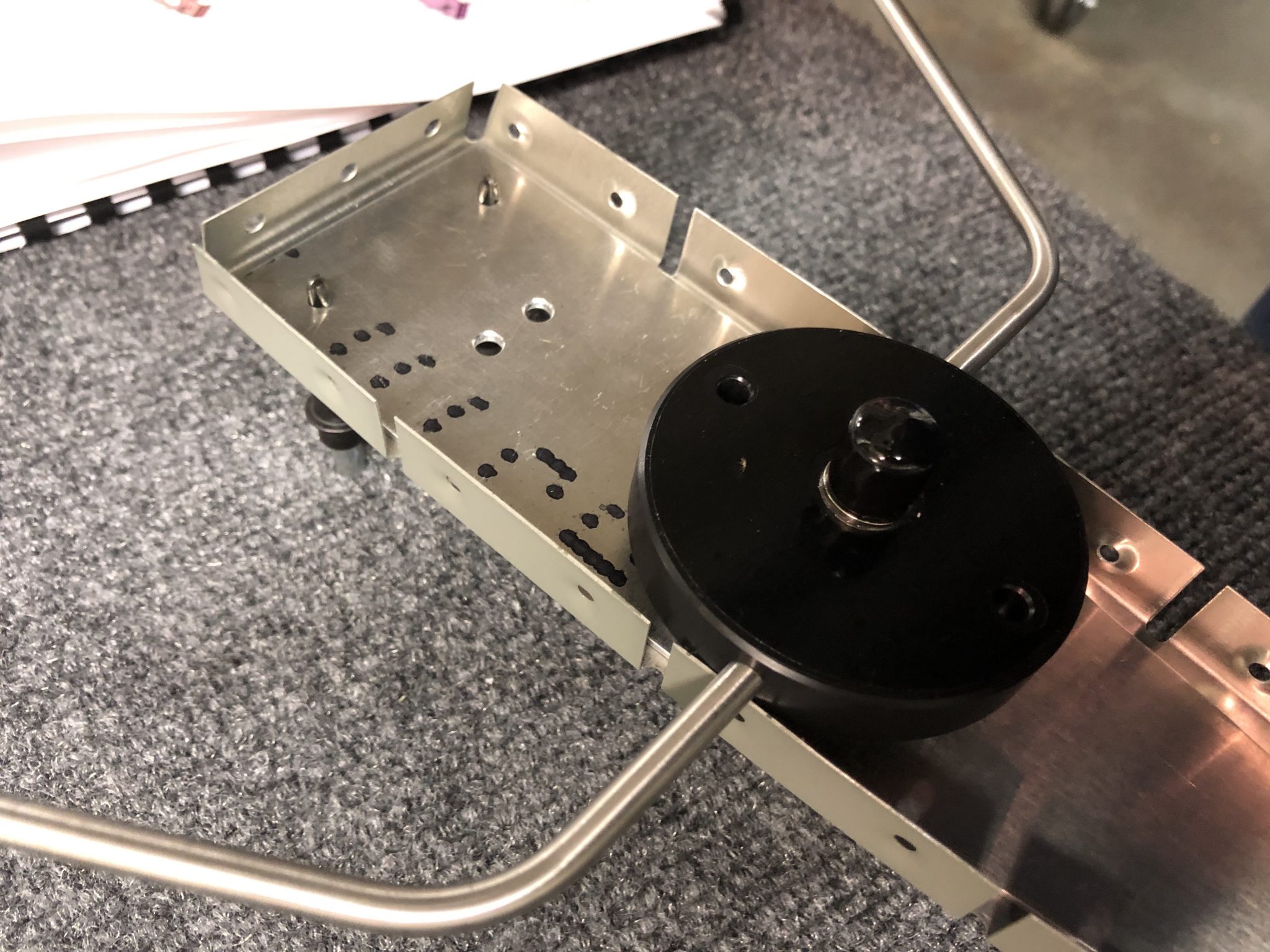
After aligning it all, I did a second small pass to trim a tiny bit more, placed it into the skin again and then it looked all good.
Tip fit in place and held in place using some clamps

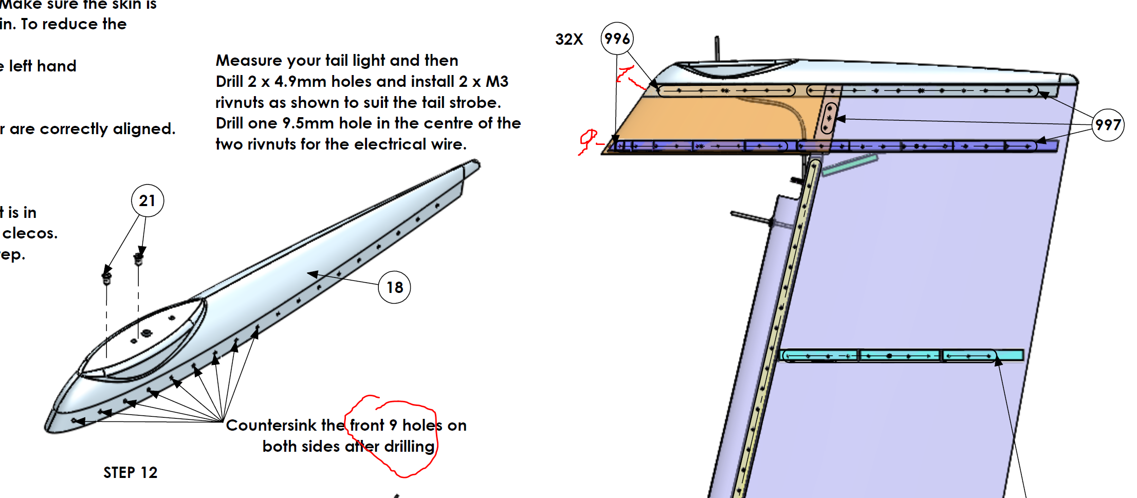
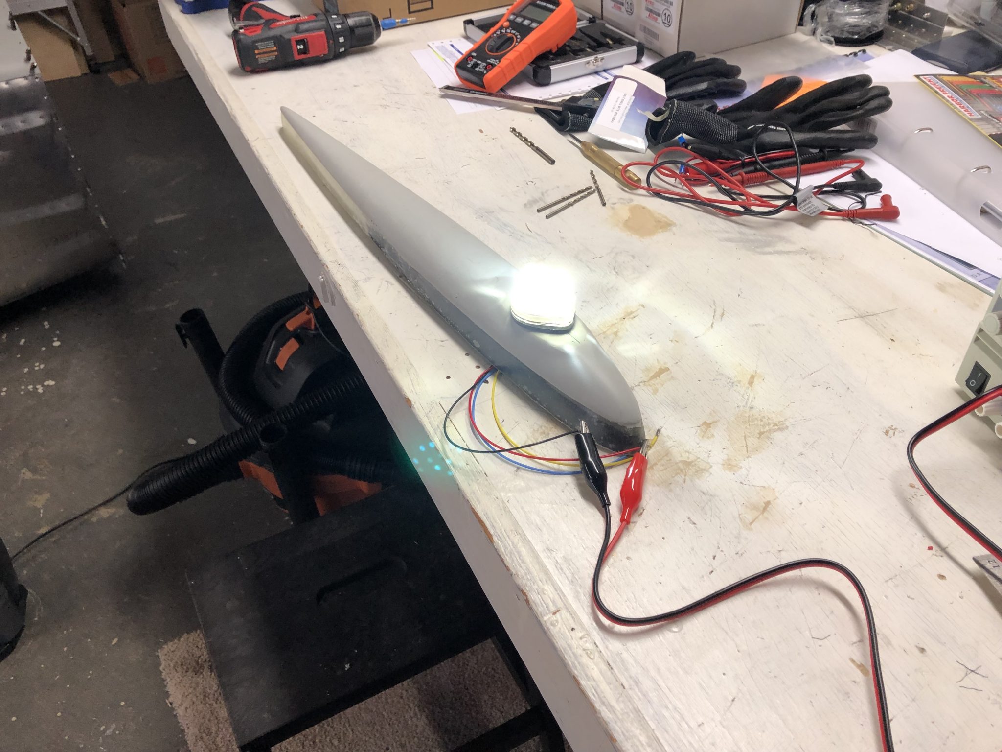
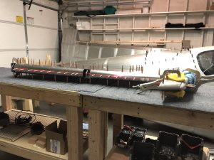
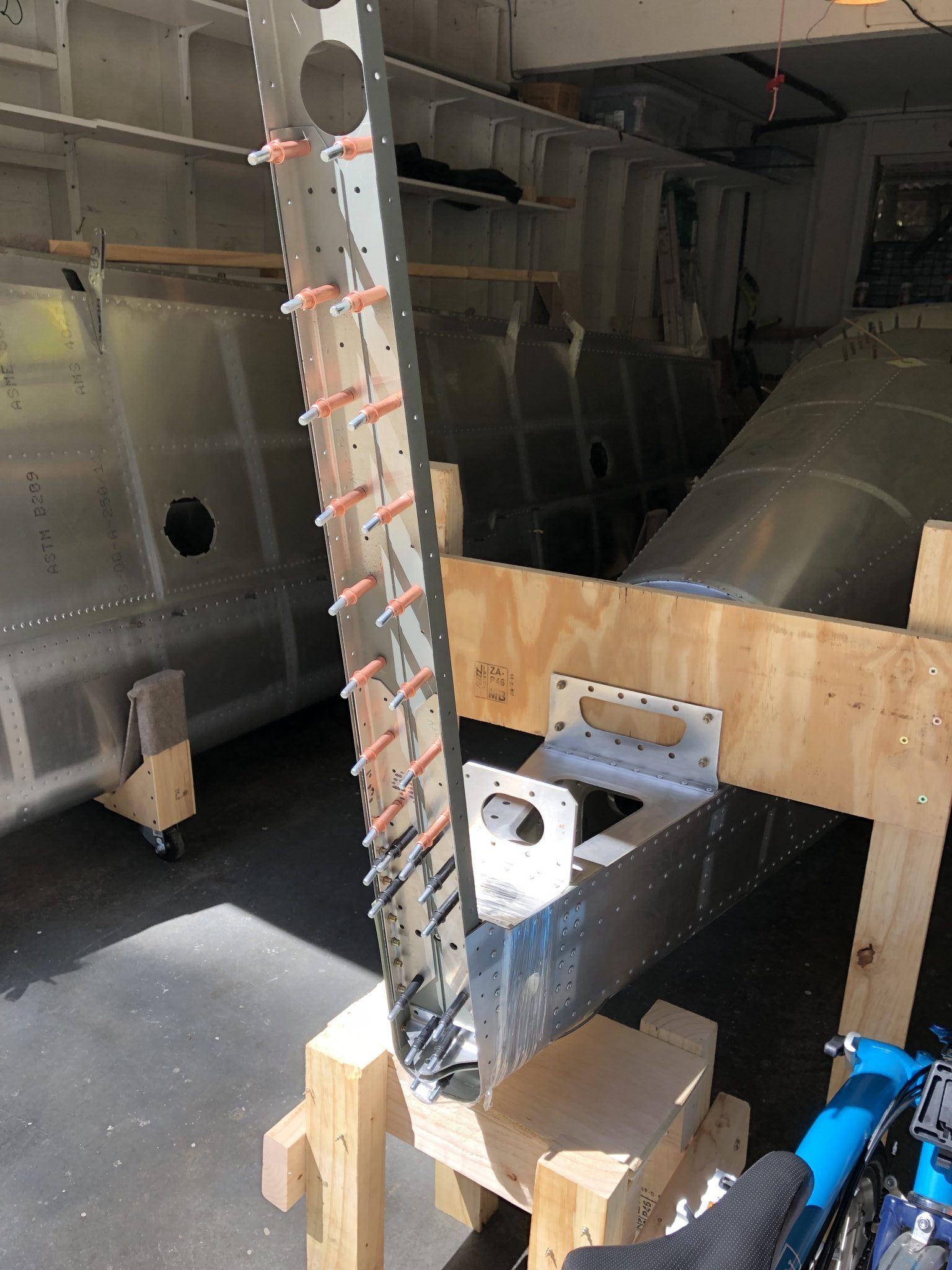
Since the instructions are very explicit to make sure that the alignment of the rudder is perfect, I checked the alignment from all sides and it all looked good.
Rudder checked for alignment using laser level Rear of the rudder checked for alignment using laser level

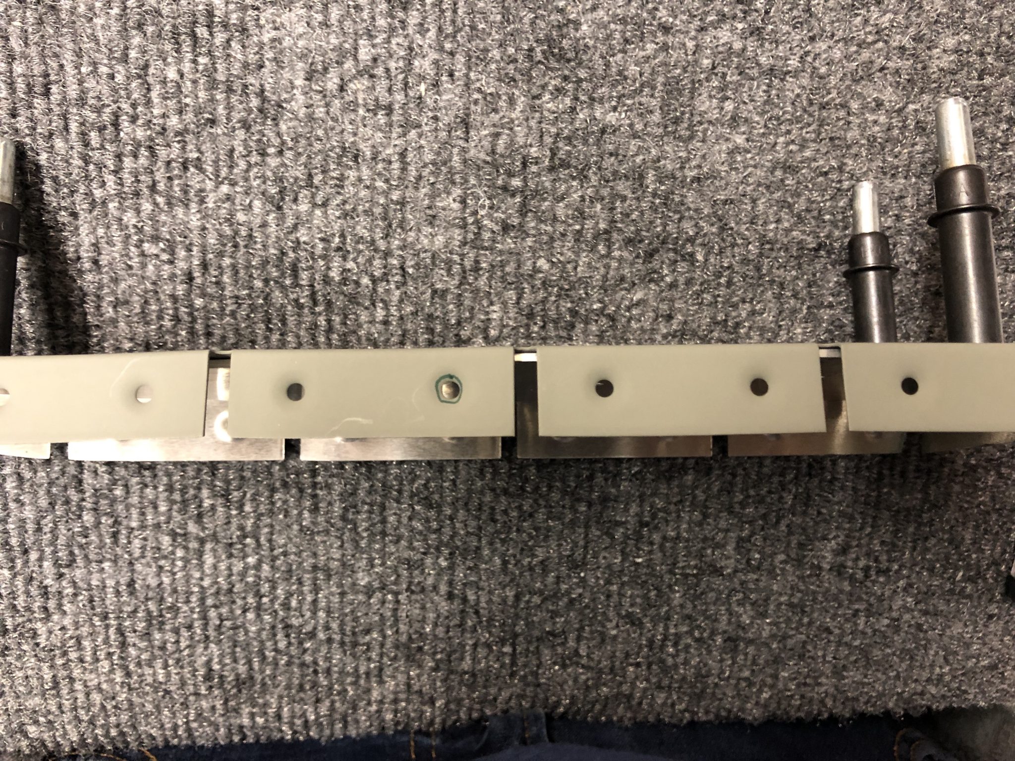
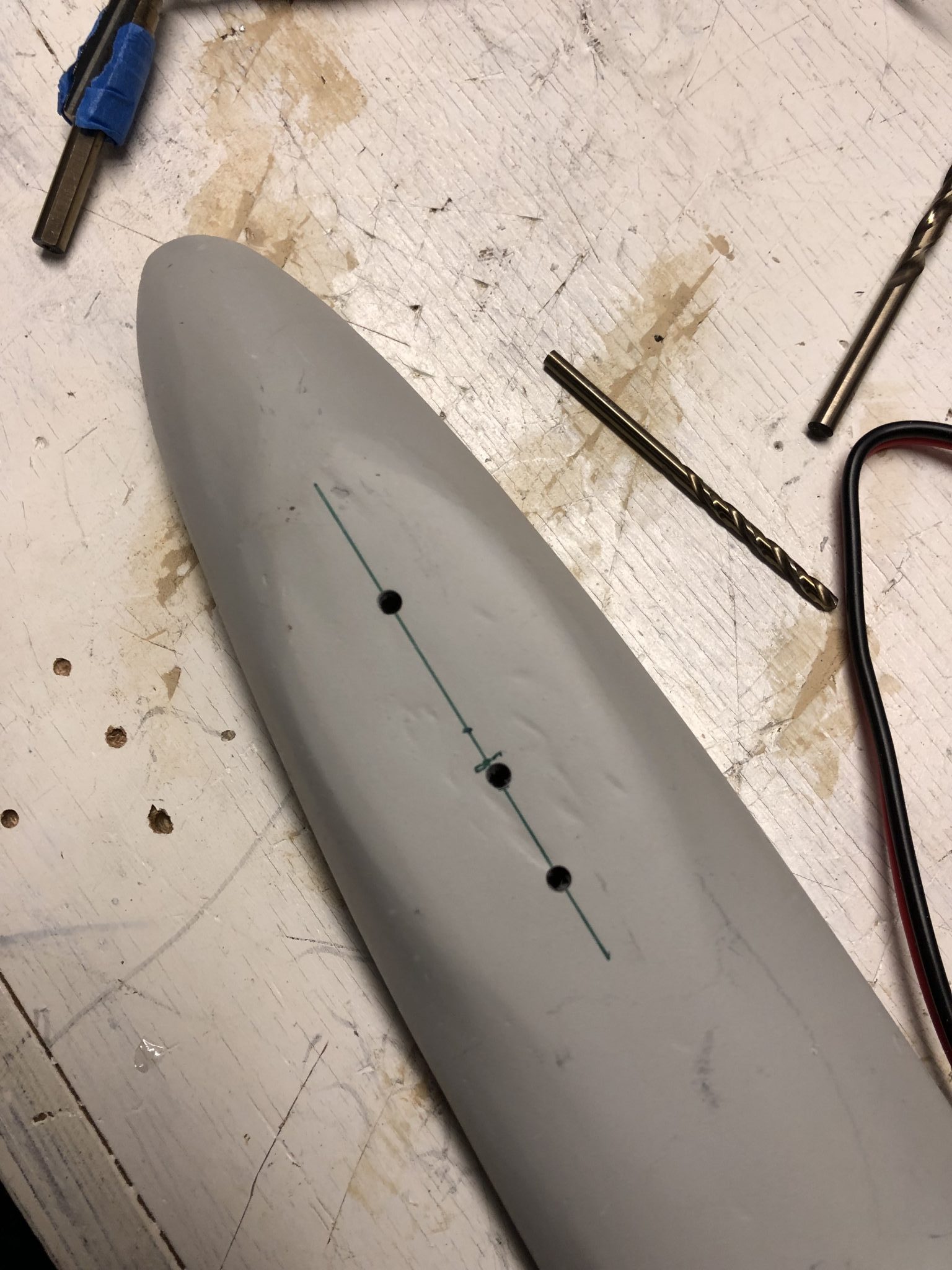
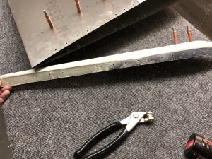
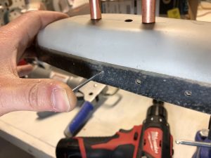
After all that looked good and triple and quadrupple checking that the fiberglass tip sat flush in the skin I made marks for match drilling the holes and then went to work and carefully drilled the holes into the fiberglass.
First few holed drilled into the fiberglass tip Finished drilling all the holes in the fiberglass tip

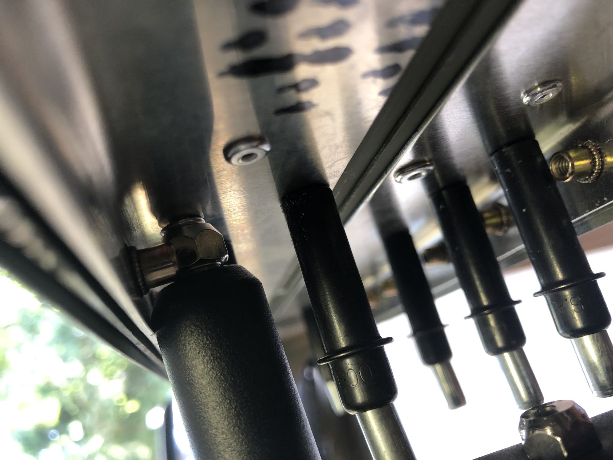
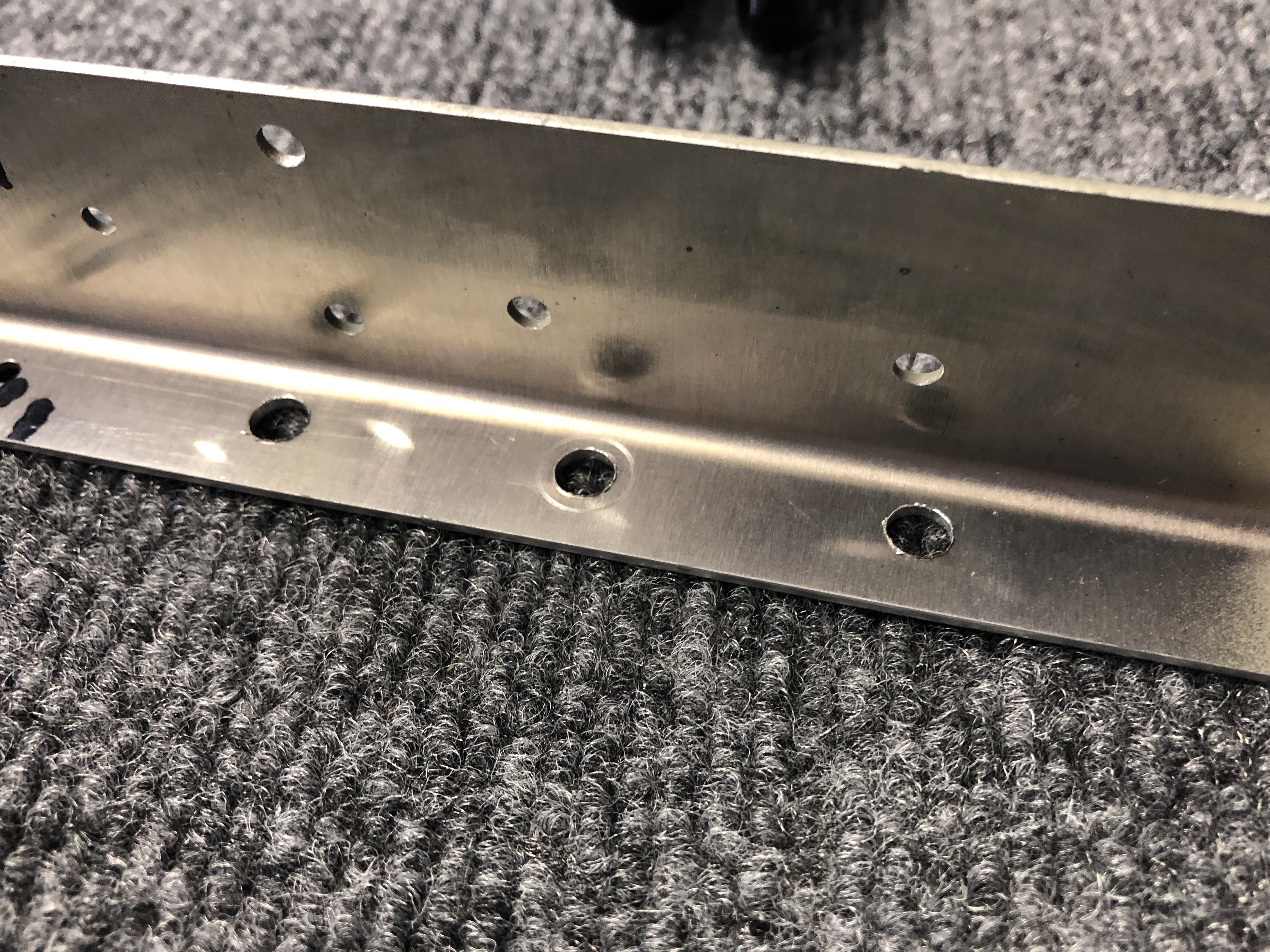
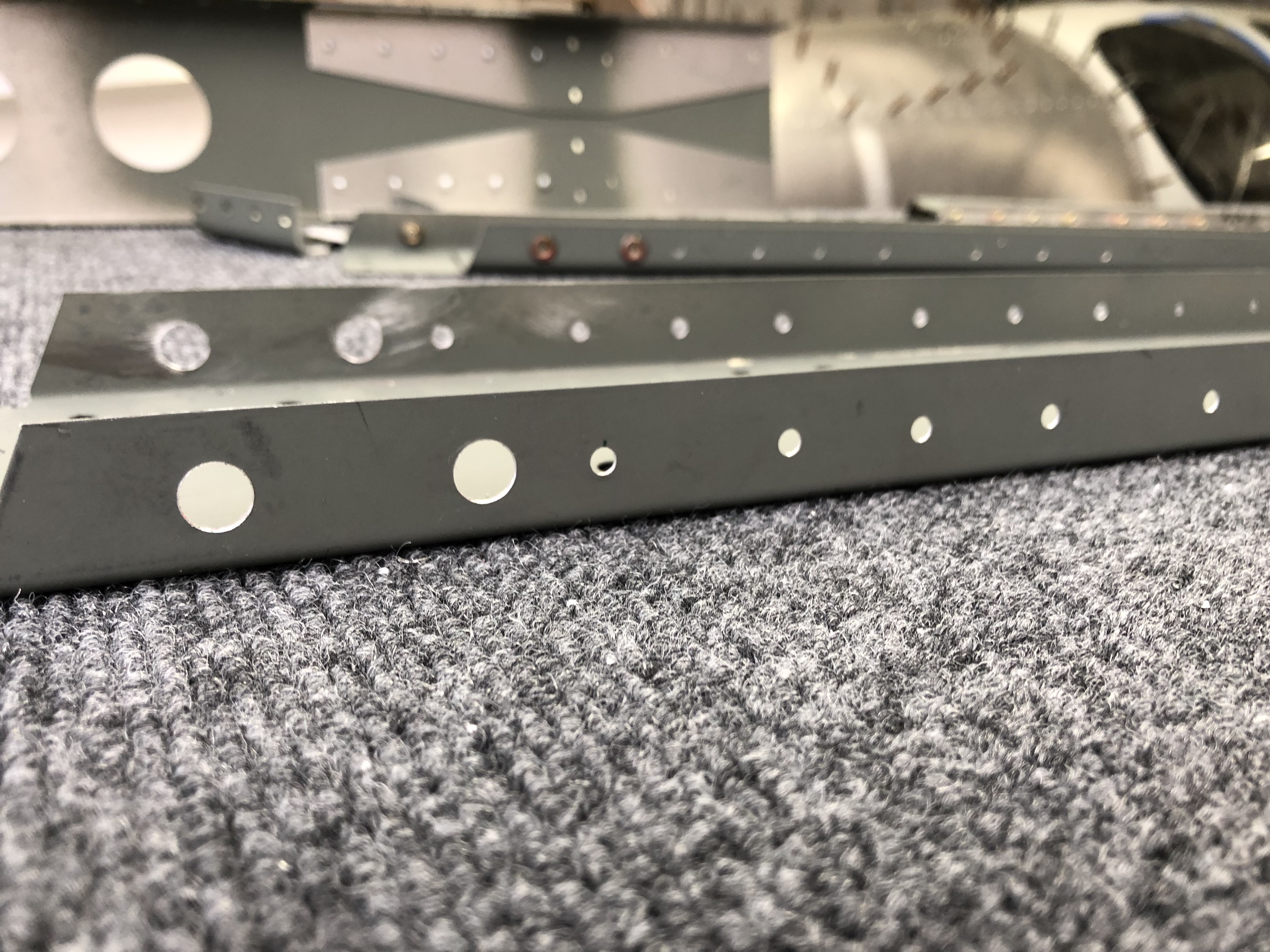
Countersinking the front of the fiberglass tip

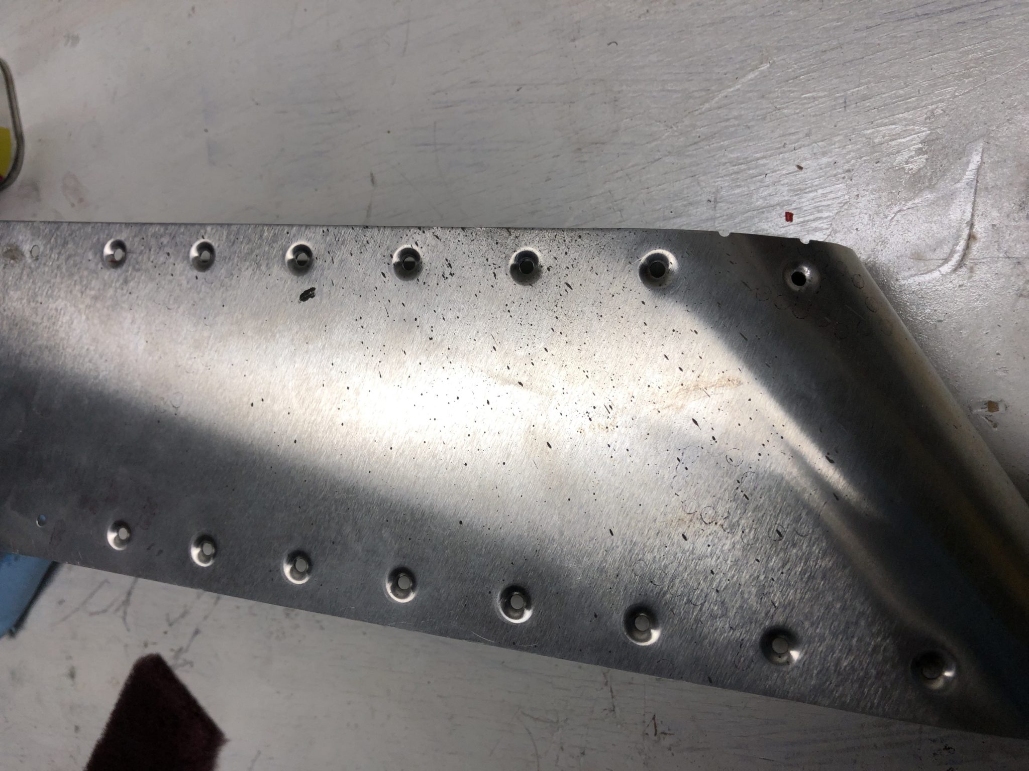
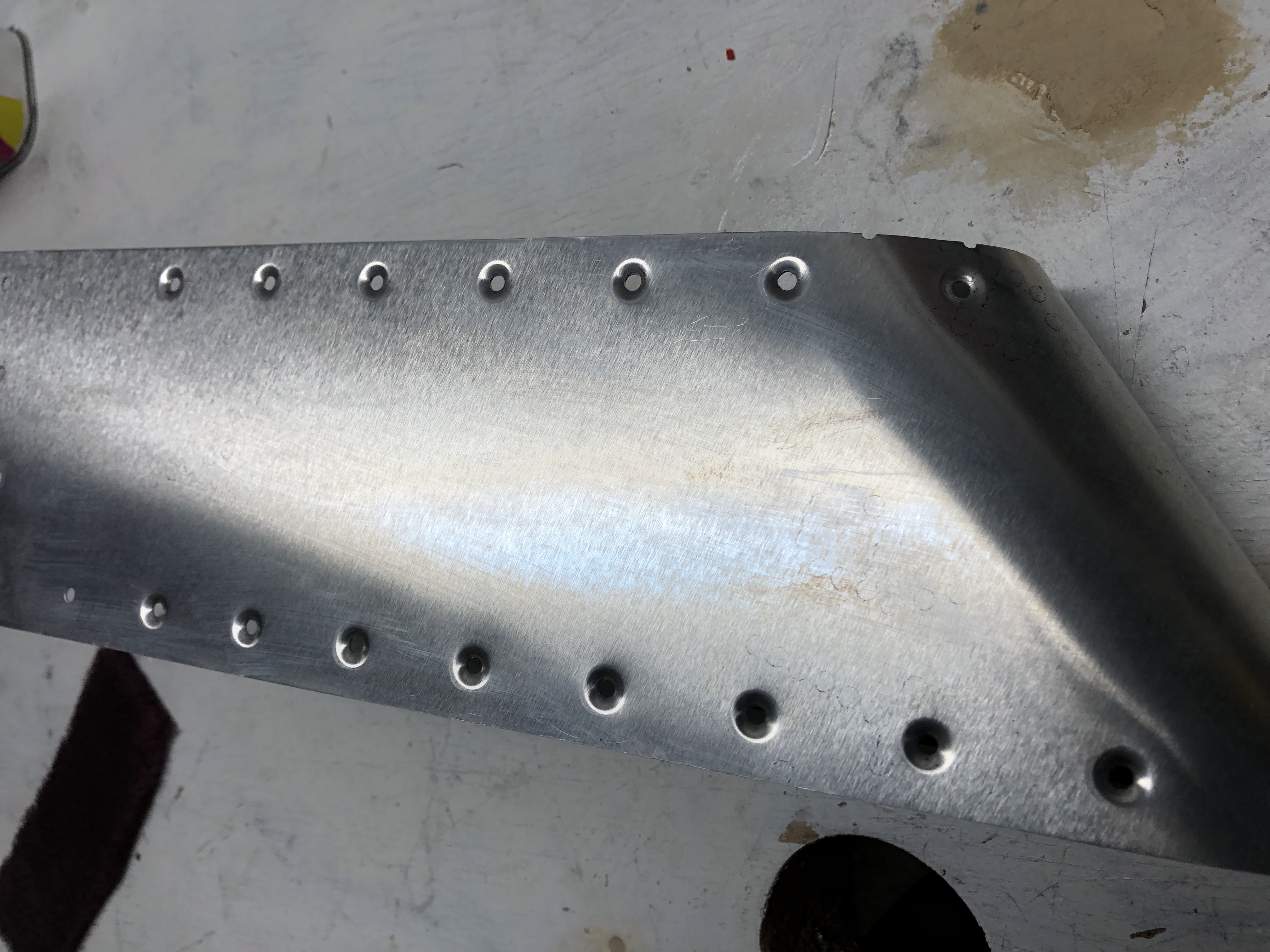
Once that was done, it was time to countersink the holes in the front. The instructions contradict themselves – only the first 7 holes get countersunk rivets, which mathematically adds up properly to the 32 rivets (2 x 7 on the top and 2 x 9 on the bottom = 32). So after counting all the holes and re-checking the instructions and doing basic math, I decided to only countersink the first 7 holes. I sent an email to the factory yesterday and they confirmed that I was right and they’ll fix the instructions in the next iteration.
Instruction error about countersinking

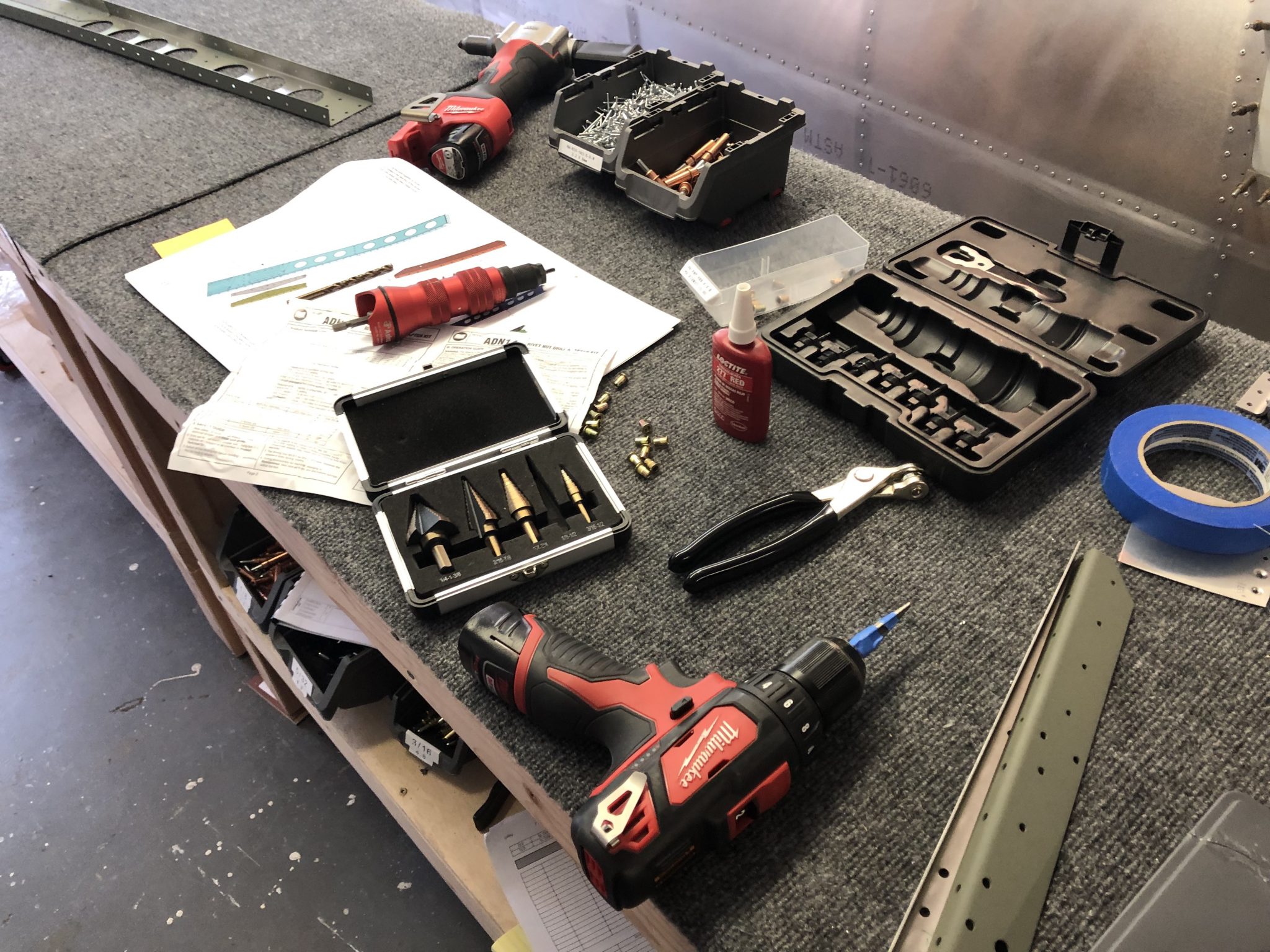
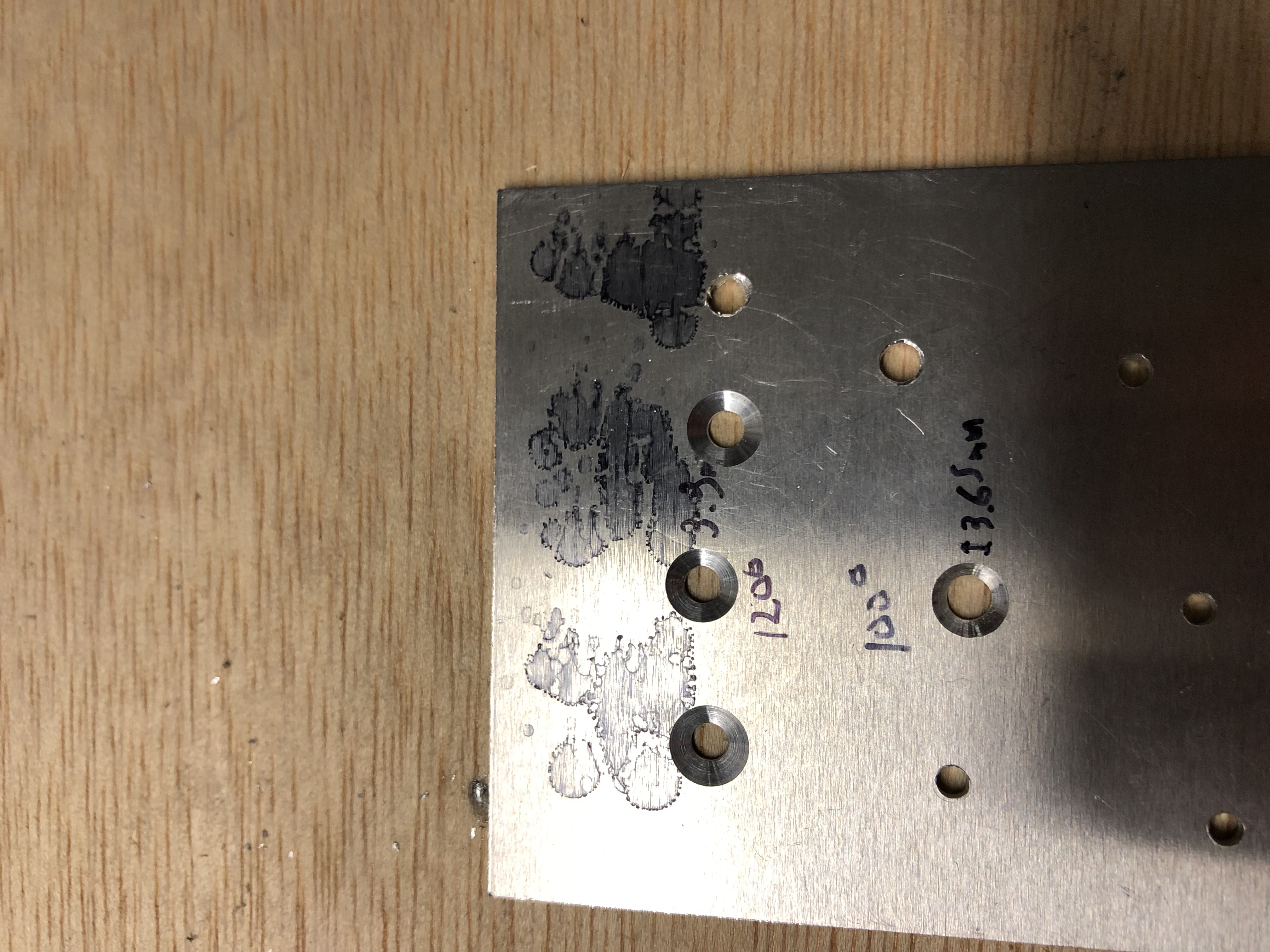
Before I went to work with the countersinking, I calibrated the micro stop countersinking tool using a scap piece of Aluminum to ensure the depth was set correctly and made sure that I had the correct 120 degree pilot cutter in the tool (I made a whole post about why using the 120 degree pilot was important here).
Calibrating the Microstop Countersinking tool Making a test countersink on a scrap piece of metal

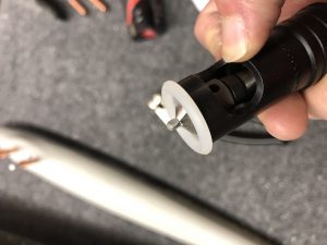
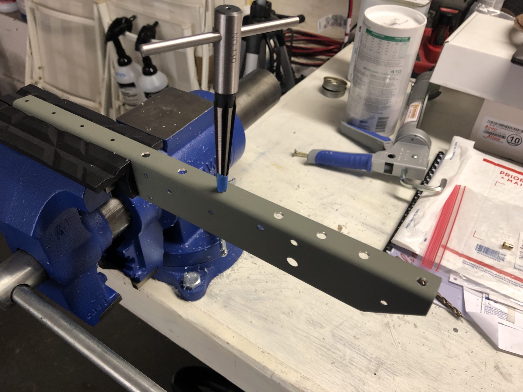
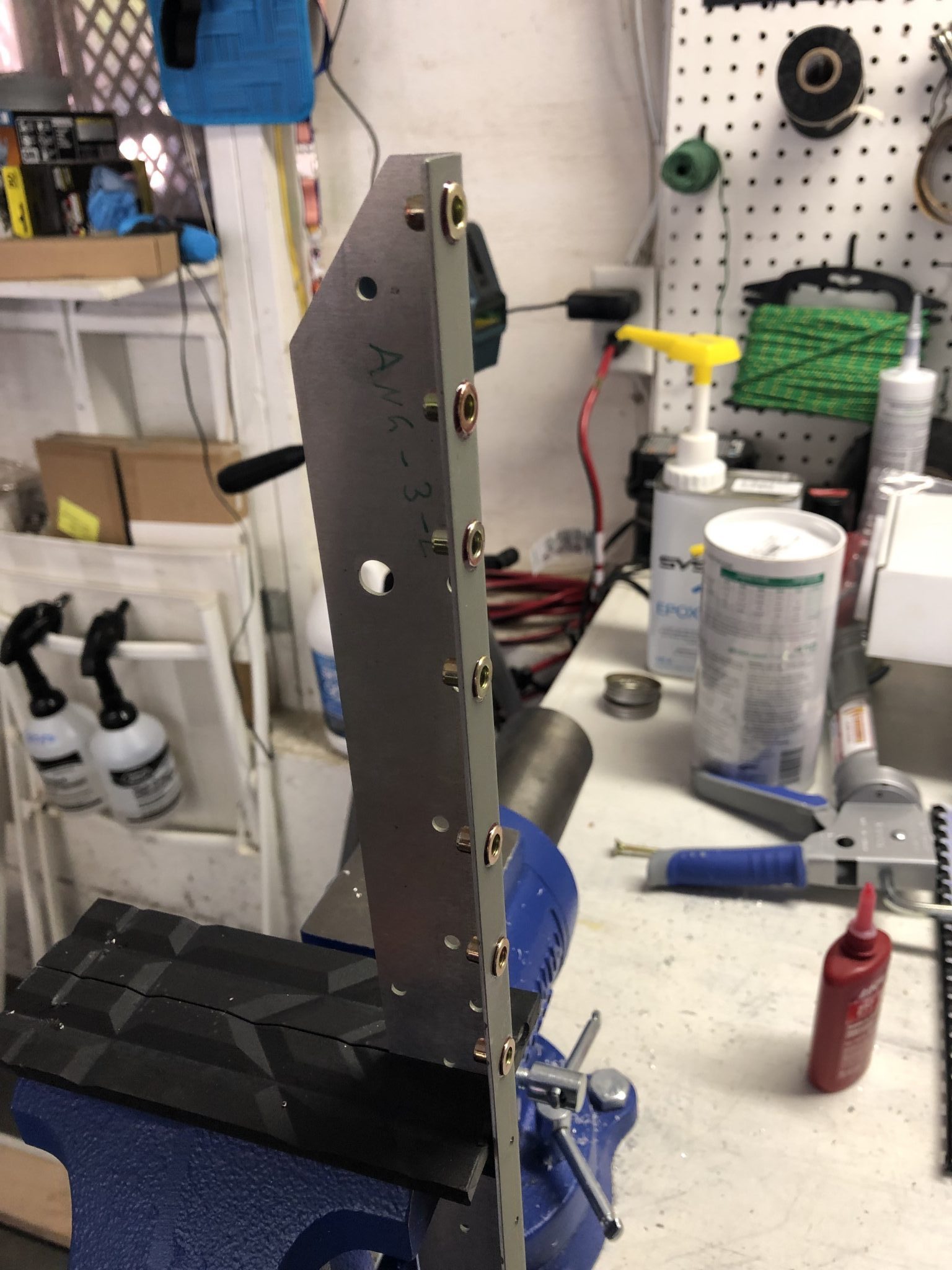
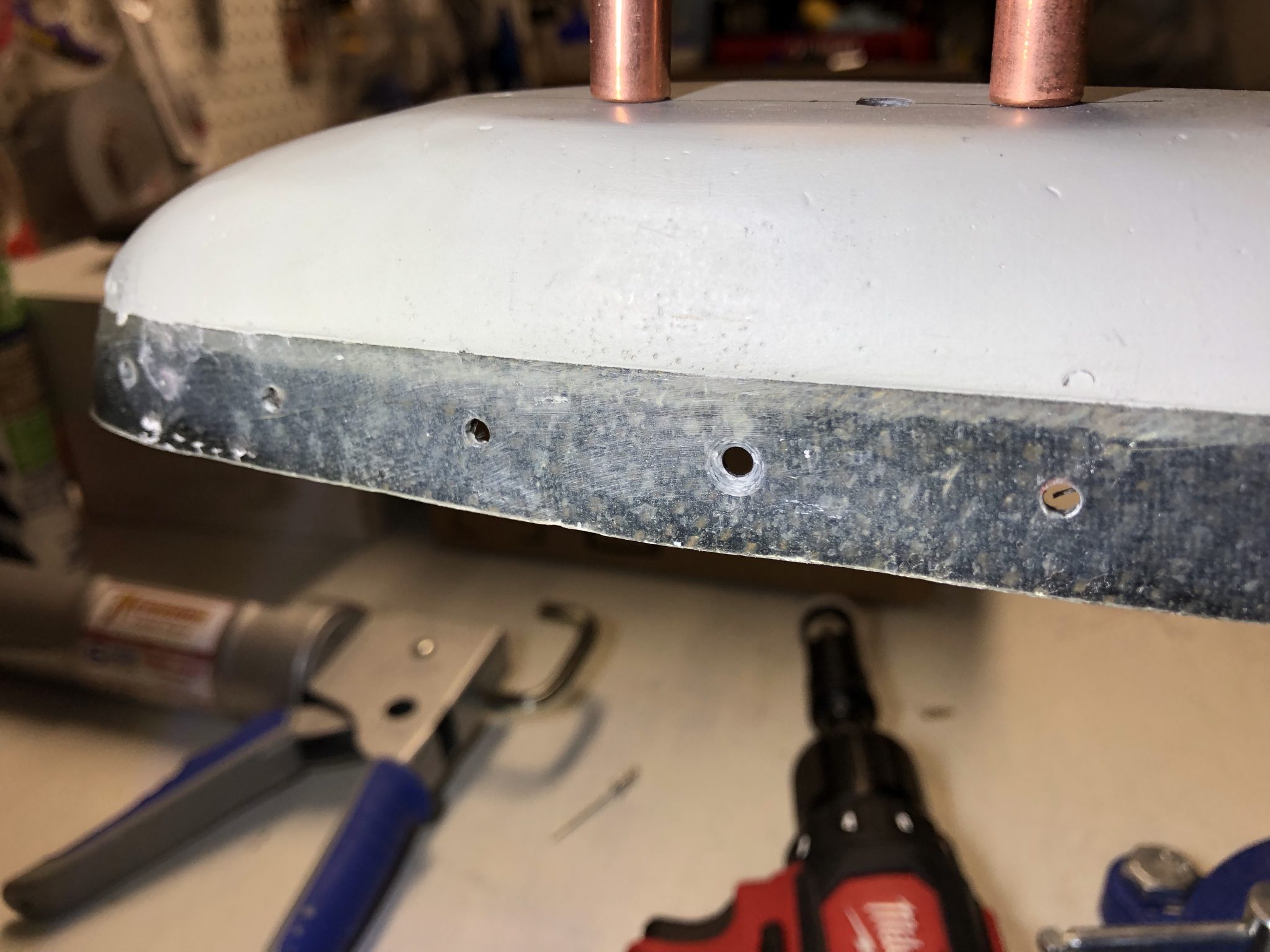
After all that was ready, I went to work, mounted the fiberglass tip gently in my bench vise and started drilling the countersink holes.
First countersunk hole drilled Checking depth using a countersunk rivetAll the countersunk holes drilled in the fiberglass tip

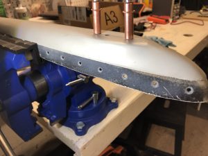
All the countersunk holes came out well and everything sits flush now.
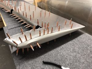
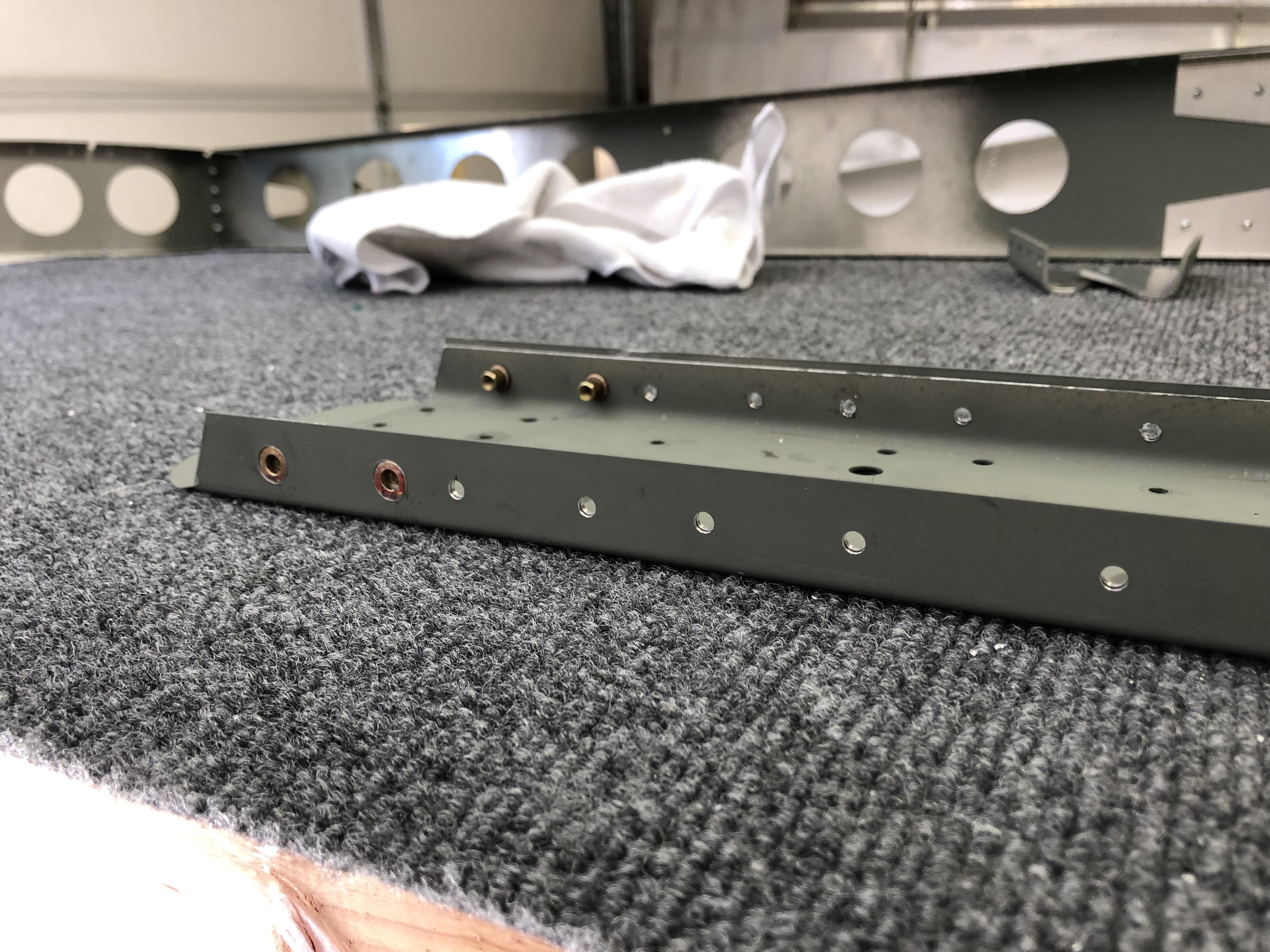
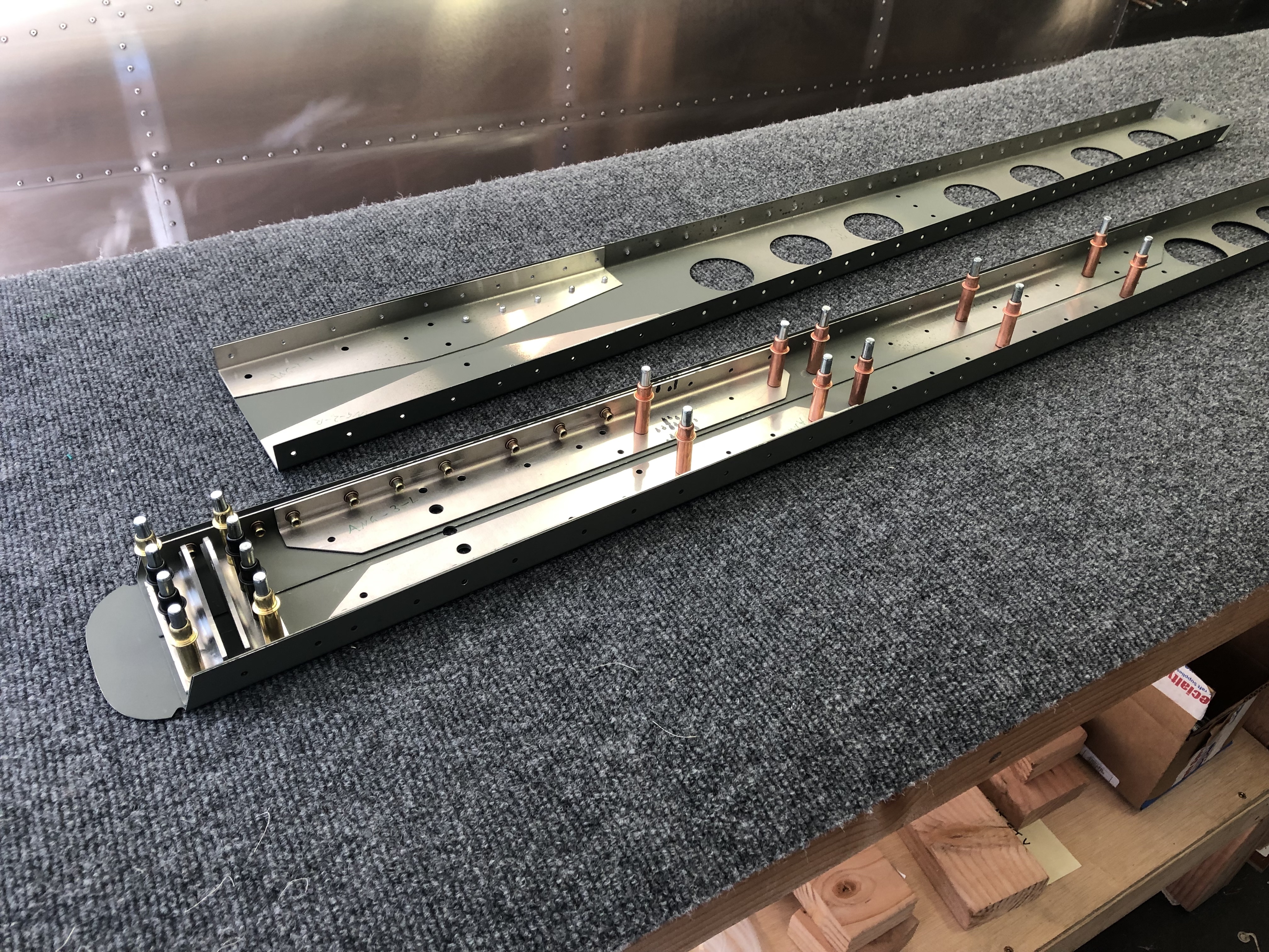
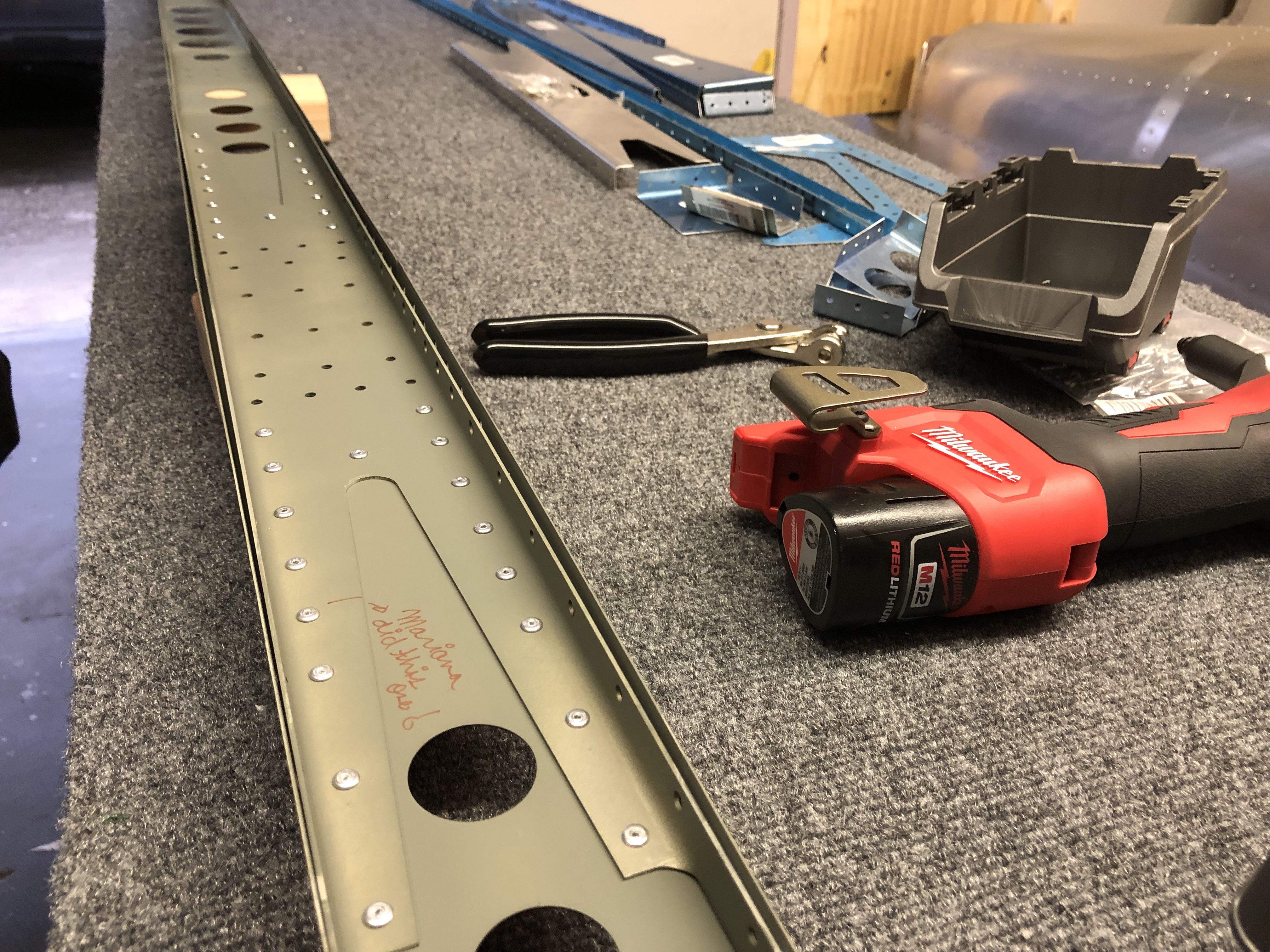
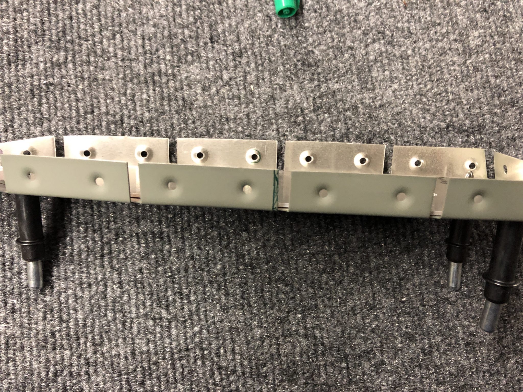
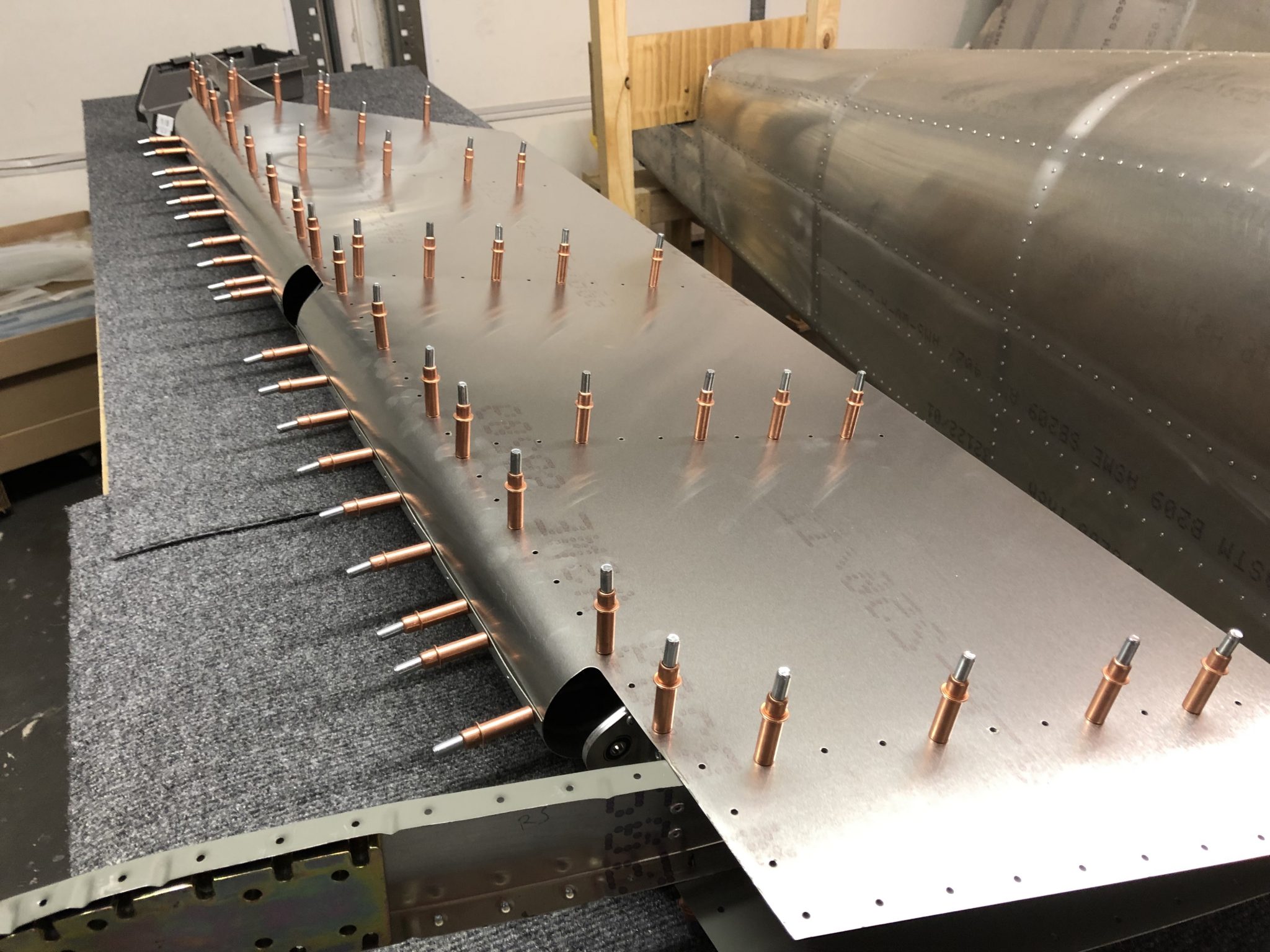
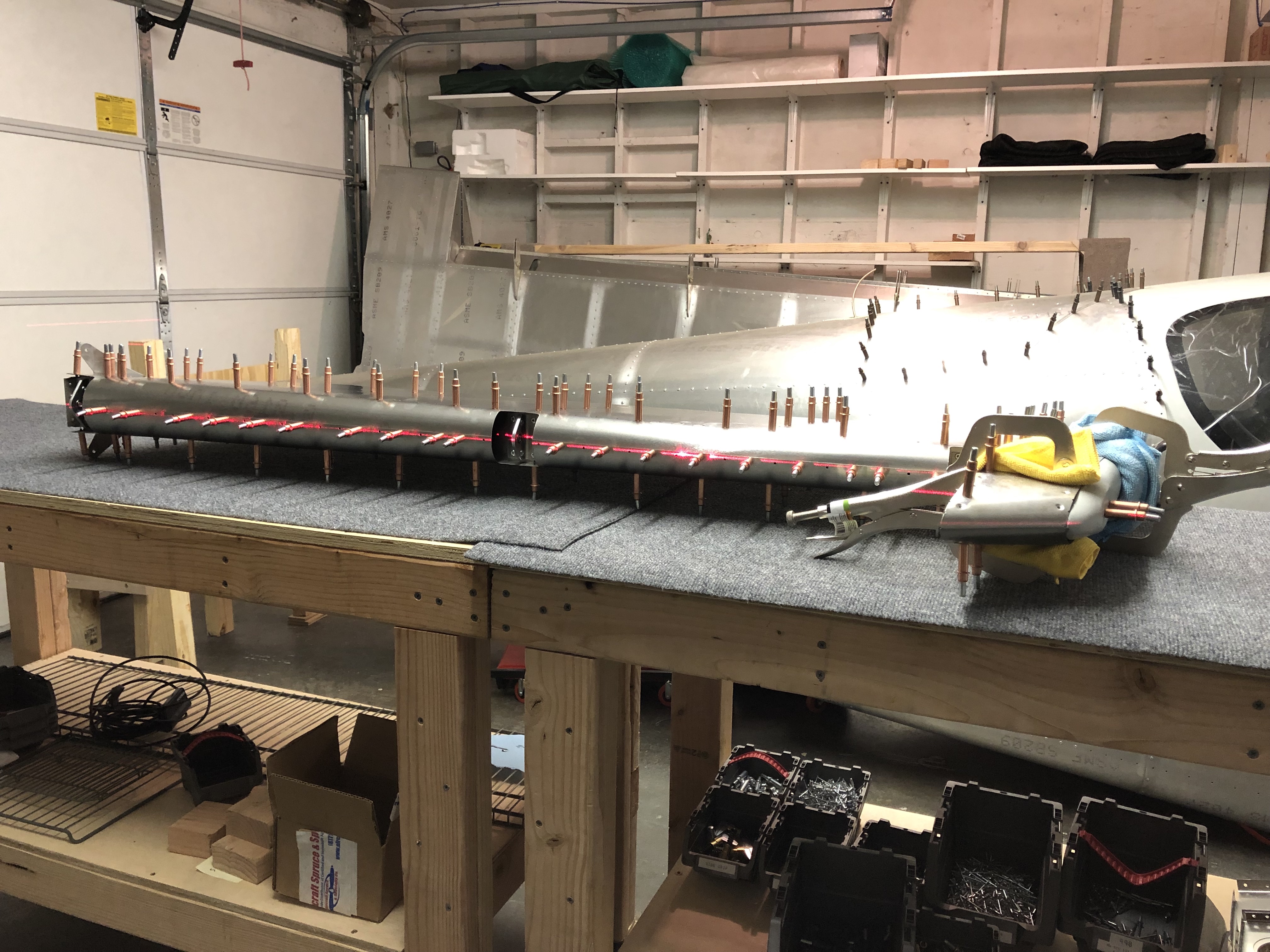
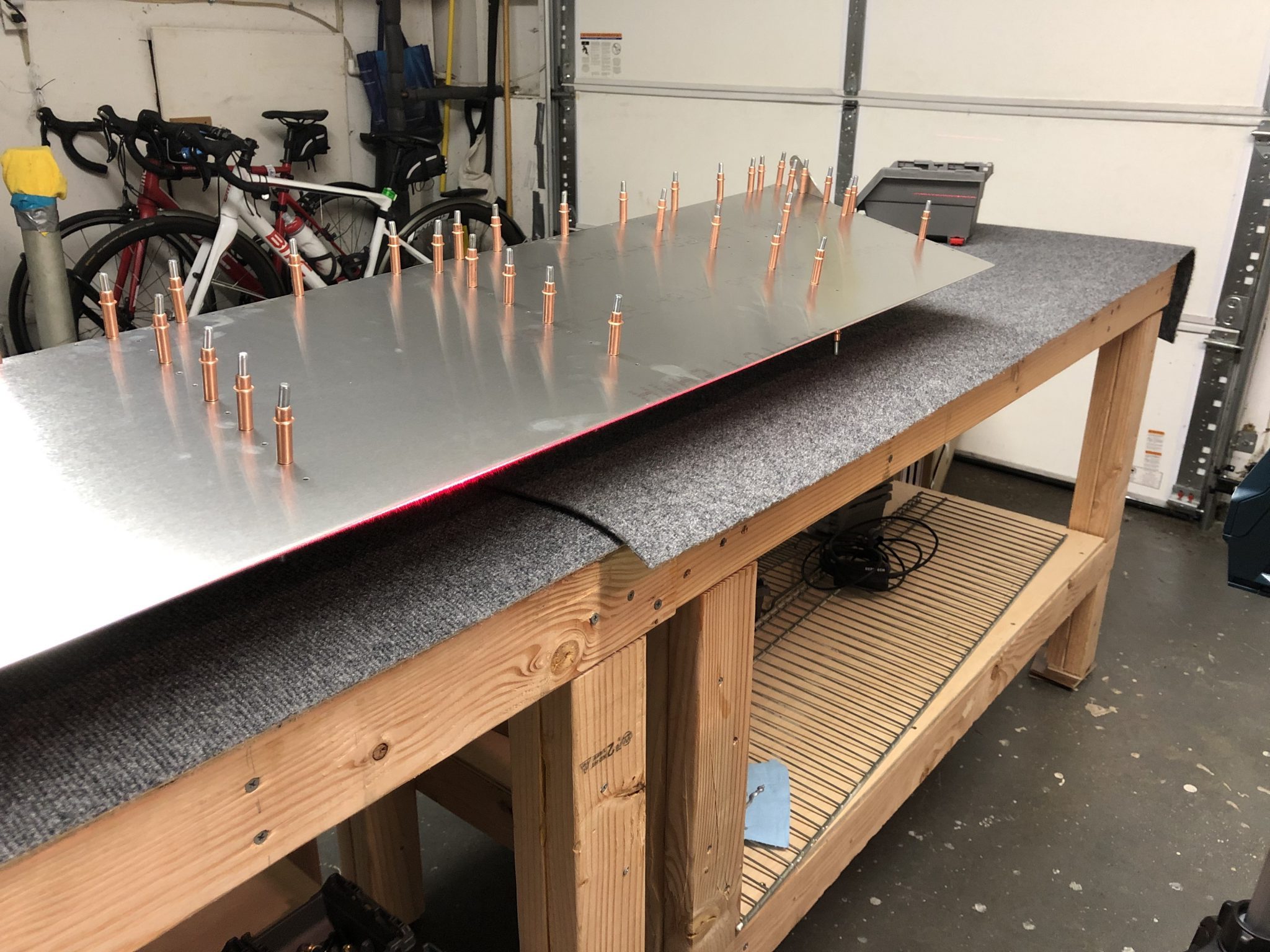
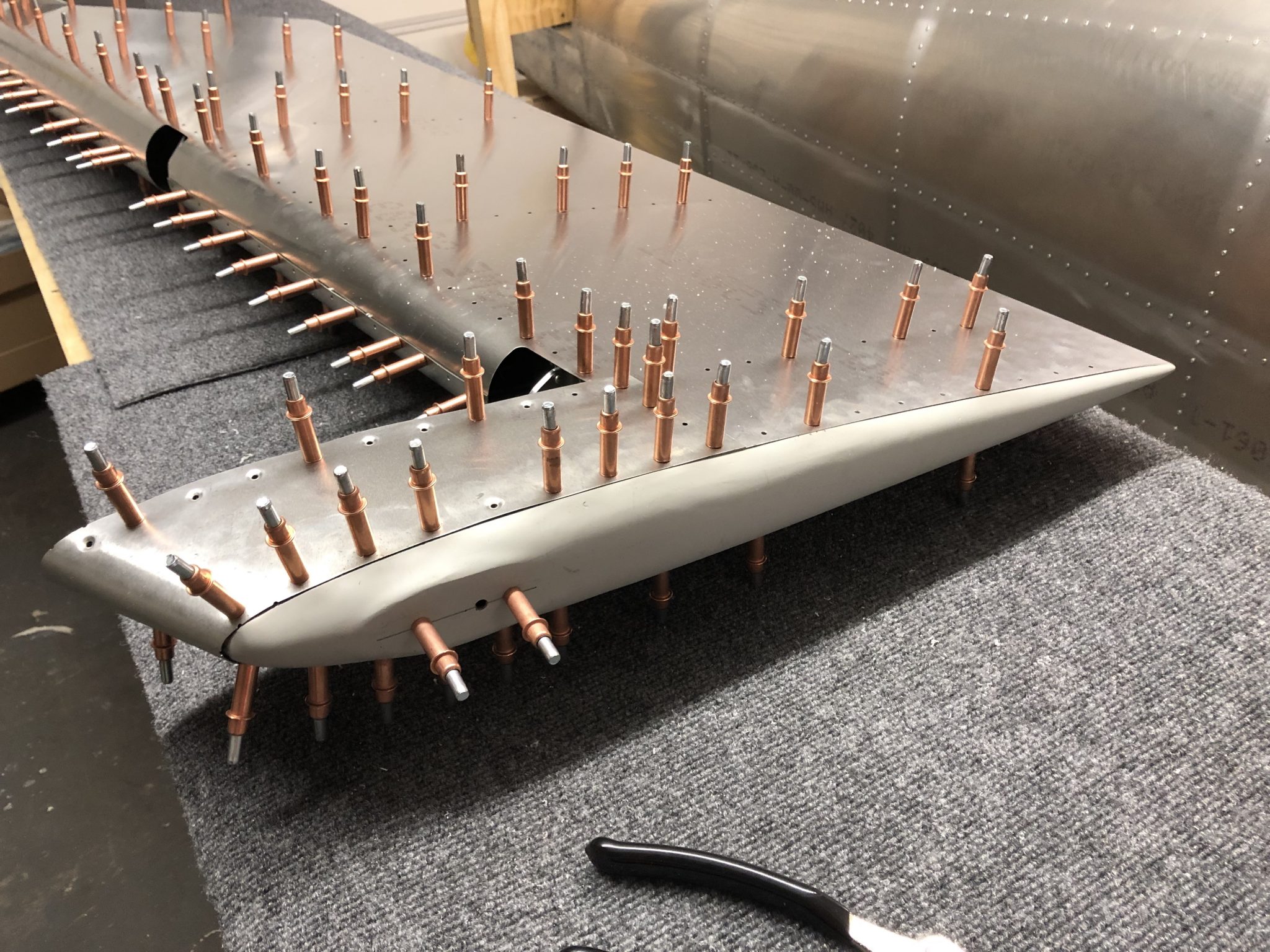
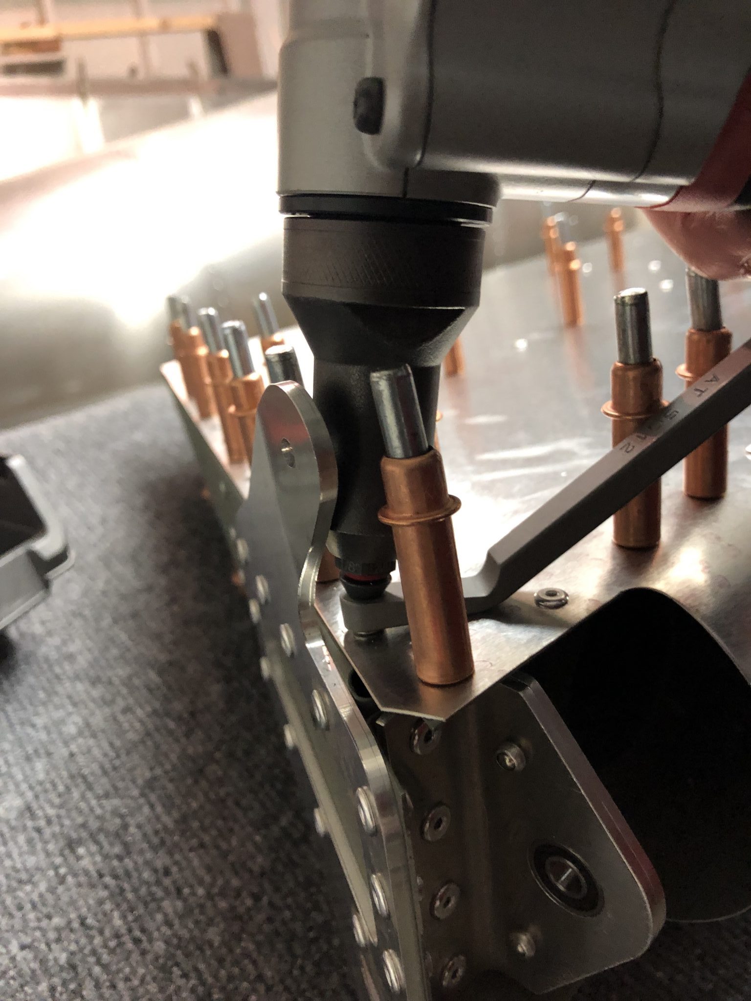
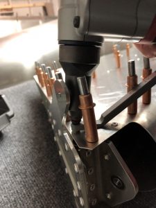
Flush fit of the fiberglass tip in the Rudder

Riveting the skin

So after all that I went to work and started riveting some of the skin.
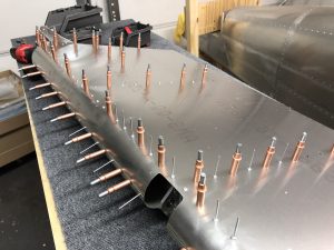
Time to rivet the Rudder skin The close quarter wedge came in handy for riveting in this tight spaceRiveted part of the Rudder skin

Vertical Stabilizer Priming

Hours: 2

In order to finish up the Rudder, I still had to prime the inner mating surfaces of the skin, so in order to get ahead I decided to also prepare the parts for the Vertical Stabilizer and prime those as well.

After removing all the protective plastic from the parts and inspecting them, I unfortunately found that there was some dents in Rib 1, 2 and 3, so I requested replacements from the factory since those are structural parts that shouldn’t be compromised.

I still went ahead and cleaned and degreased all the other parts. Luckily it’s getting a bit warmer, so I could leave the garage door open and do the cleaning outside, to make less of a mess in the garage.

Vertical Stabilizer parts laid out to inspect Cleaning Station with Simple Green cleanerParts cleaned and ready to be primed

Once I was done cleaning all the parts with Simple Green, degreasing them with MEK and rubbing them down with red scotch brite, I set up my small paint booth and primed everything.

Paint booth ready to prime Done priming the parts of the Vertical Stabilizer

Rudder skin fitting & Anti-Collision light mount

Hours: 3

Over the past few days I spent some time organizing the next few parts of the Empennage such as organizing the Vertical Stabilizer parts and what I needed to finish for the Rudder.

Fitting the Anti-collision light

I got the Aveo Posistrobe MiniMax anti-collision light to mount onto the rudder tip and started working on fitting it on.
Aligning the strobe light seal to find out where the holes should go Marking center linePilot holes drilled Double checking the holes aligned properly and then enlarging the hole for the wires to pass through
Light temporarily on top and shining bright like a diamond.
Quick test with light on

Mounting plate

The first iteration of the Empennage assembly instructions called out for a mounting plate to go inside the fiberglass tip to add structural reinforcement for the rivnuts, but the latest version of the instructions is missing it, so I sent a question to the factory why.

In the meantime, since I assume that it’s still a good idea since both the Sling 4 instructions as well as the first version of the instruction call for it, I decided to fabricate my own.

I started tracing out the rough dimensions of the area and then measured it down to how it would fit. Then I made a first version out of cardboard to see if the dimensions I estimated would work.
Rough outside dimensions of the strobe light traced Test fit of cardboard cutout

Looked good, so then I copied my cutout onto the sheet metal and went to work cutting it out. I used a OLFA Scoring knive to score the cut, based on a tip from HomebuiltHELP. Since my metal was pretty thick I only scored it with that and then used metal snips to cut it, but for thinner metal you can actually make the whole cut using the scoring knive to make great straight cuts.Transferred cutout onto aluminum sheet Metal piece cut and ready to drill the holes

After that, I deburred all the edges and the holes and then checked the final fit in the rudder tip.Plate fits great in the tip Clecoed in place

Fitting the skin

I also test fitted the skin onto the rudder and checked how the tip will fit in. The skin came on fairly easily, but I will have to trim a little bit of the fiberglass tip so it will fit in.
Skin fitted and fiberglass tip put in place Need to trim off a bit of the rear of the fiberglass tip

I still had to prime the inside of the skin, so now that I know it all fits together fine, I will rivet the skin on and then work on the final trimming for the rudder tip so it fits in and then I will need to match drill the holes into the fiberglass tip and countersink the front holes.