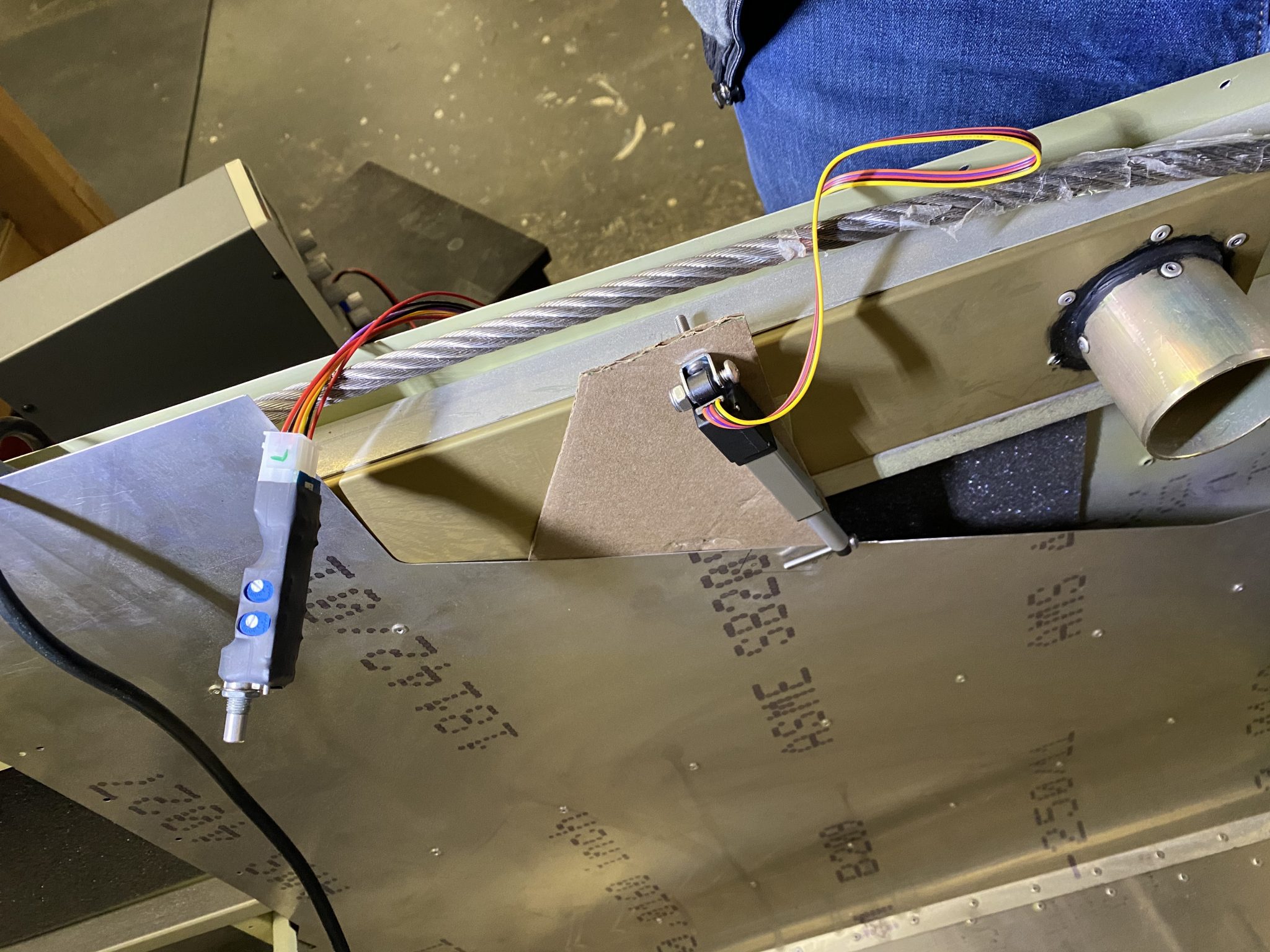
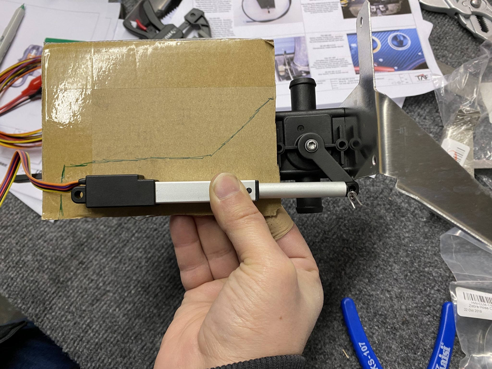
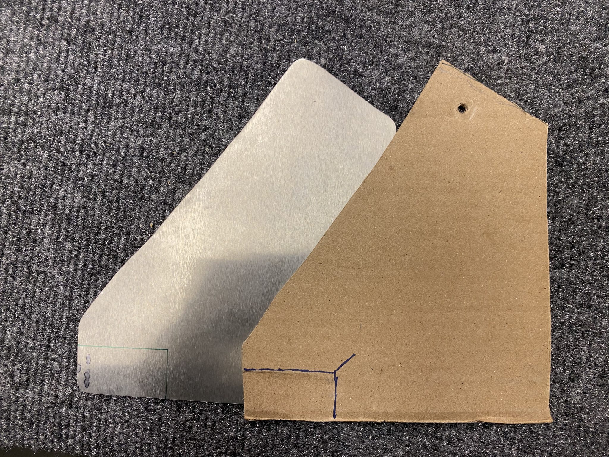
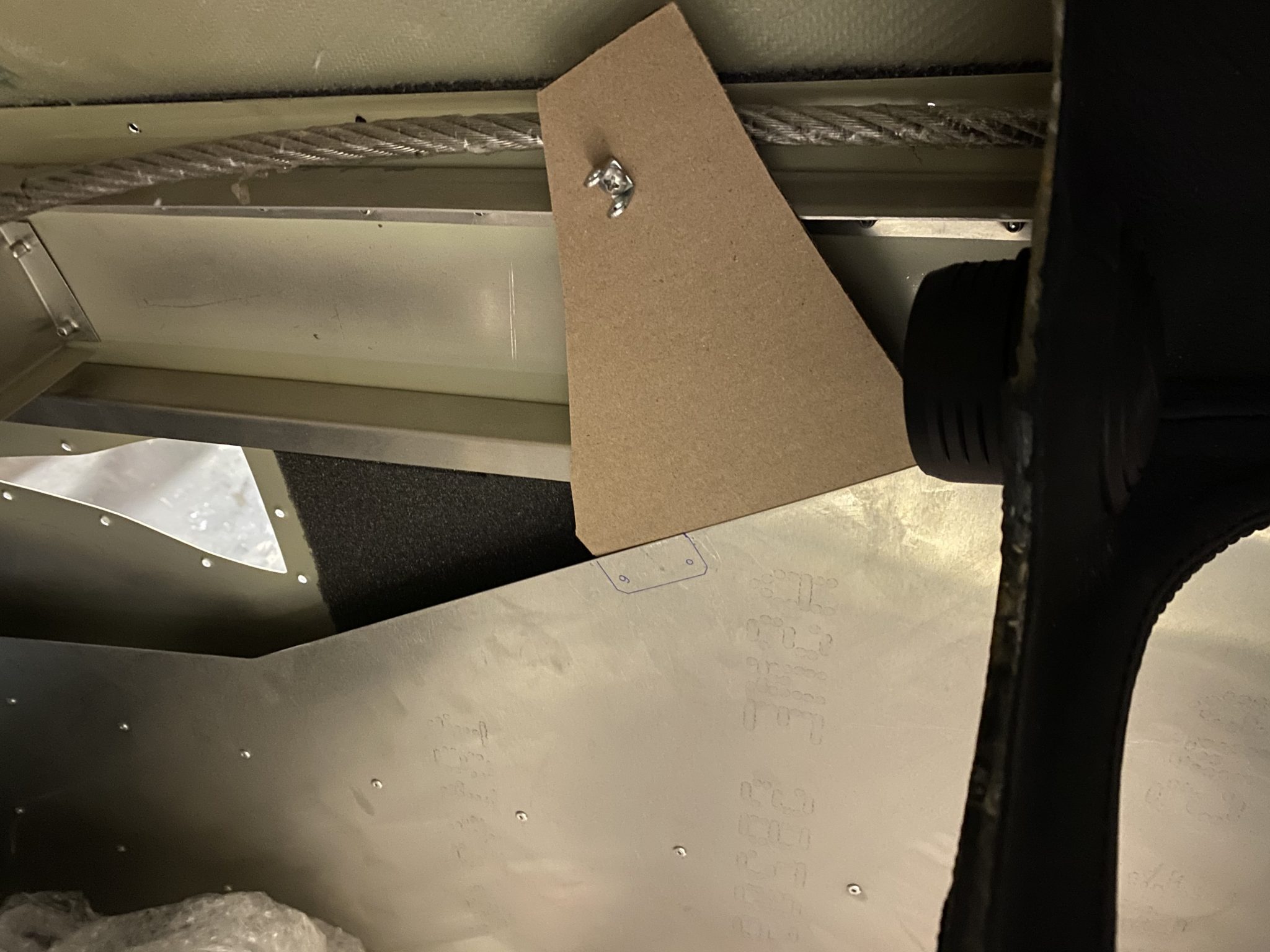
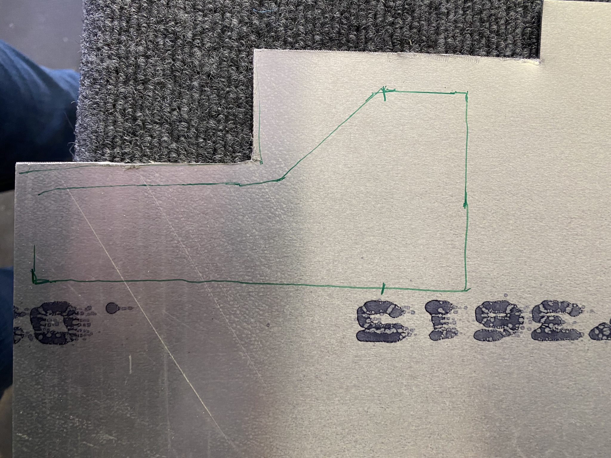
Time to turn my cardboard prototype into a permanent bracket for the heater valve.
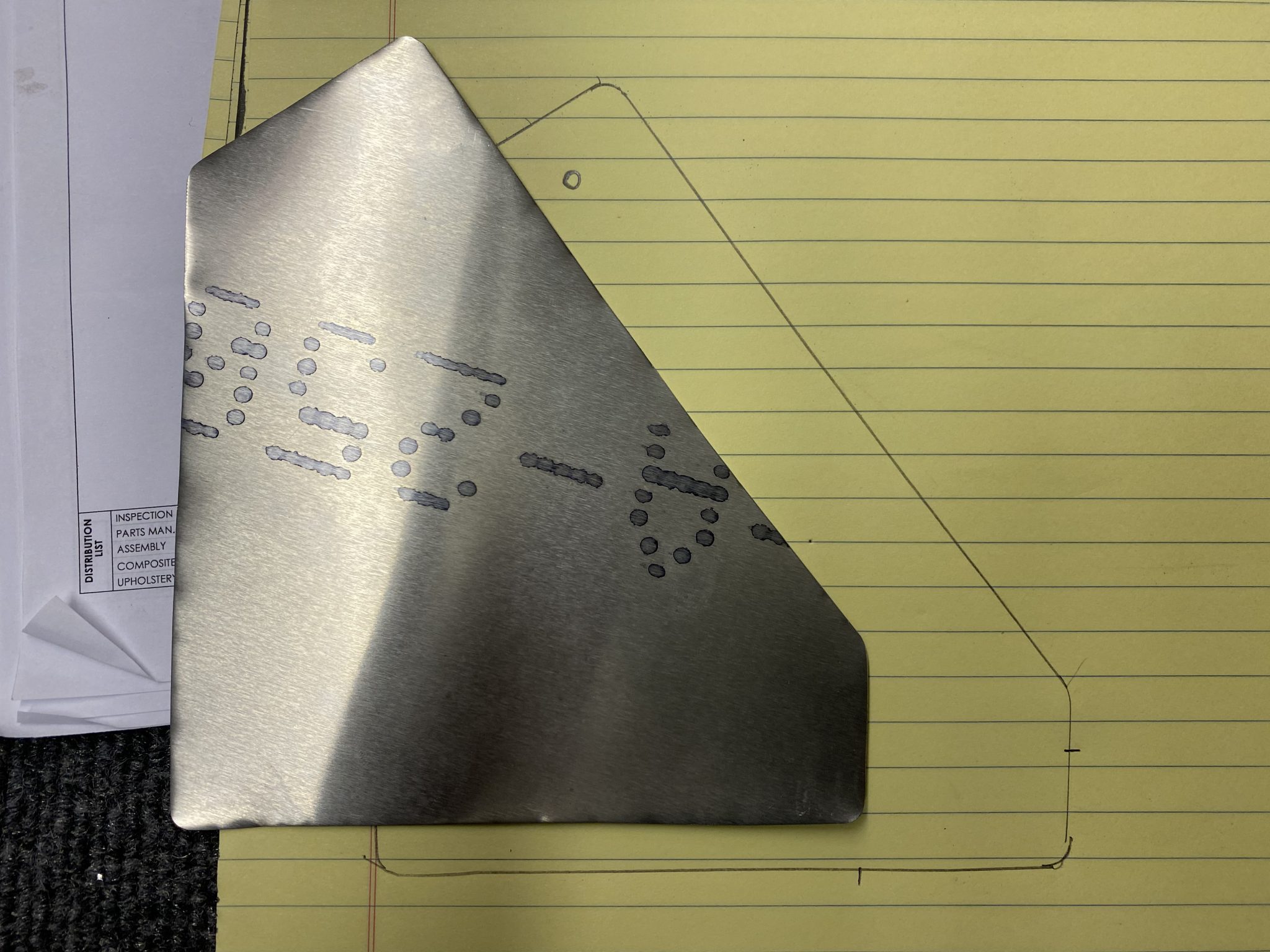
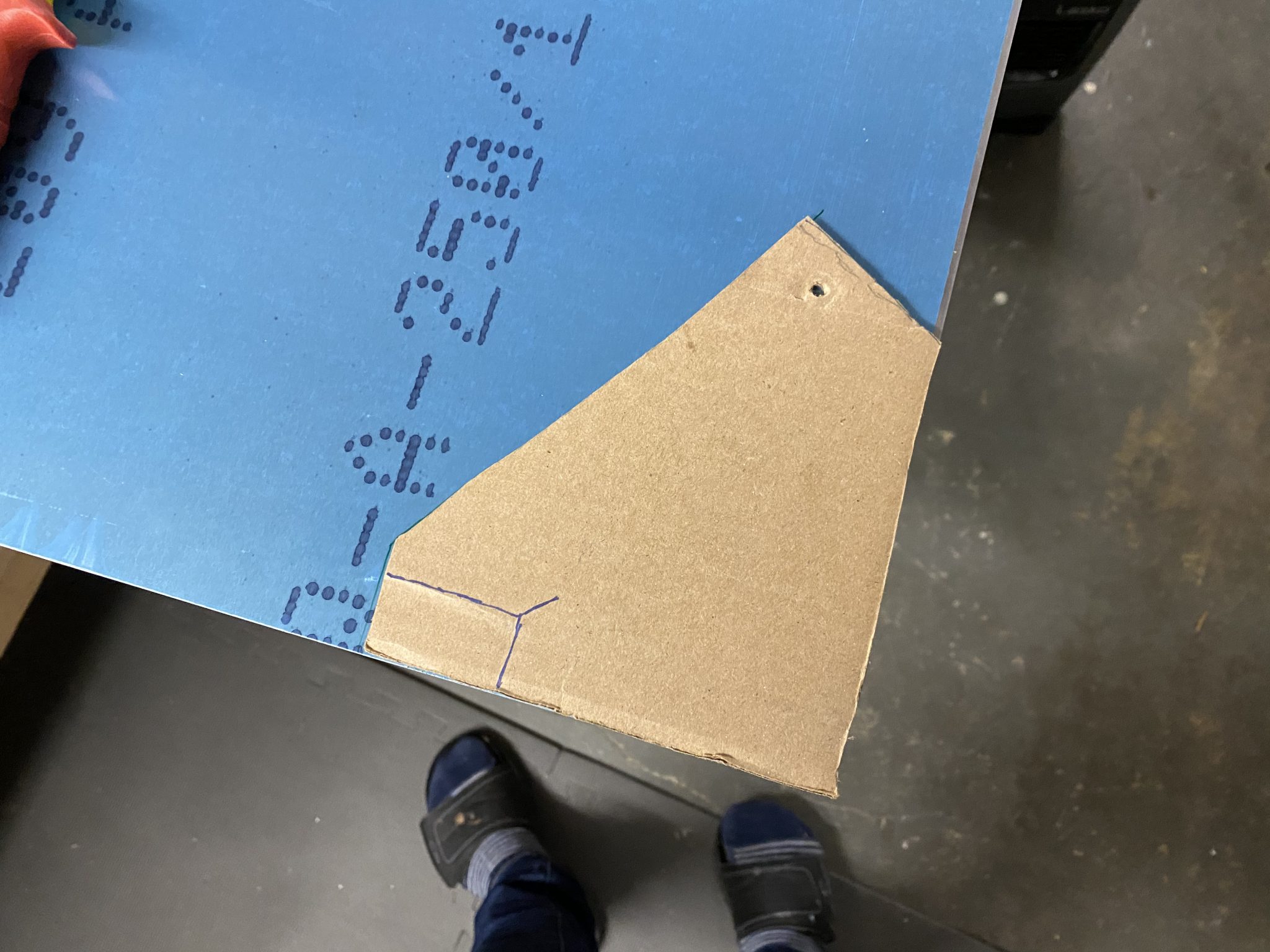
Since this bracket will sit freely, I decided to use 0.05in thick aluminum to give it some strength.
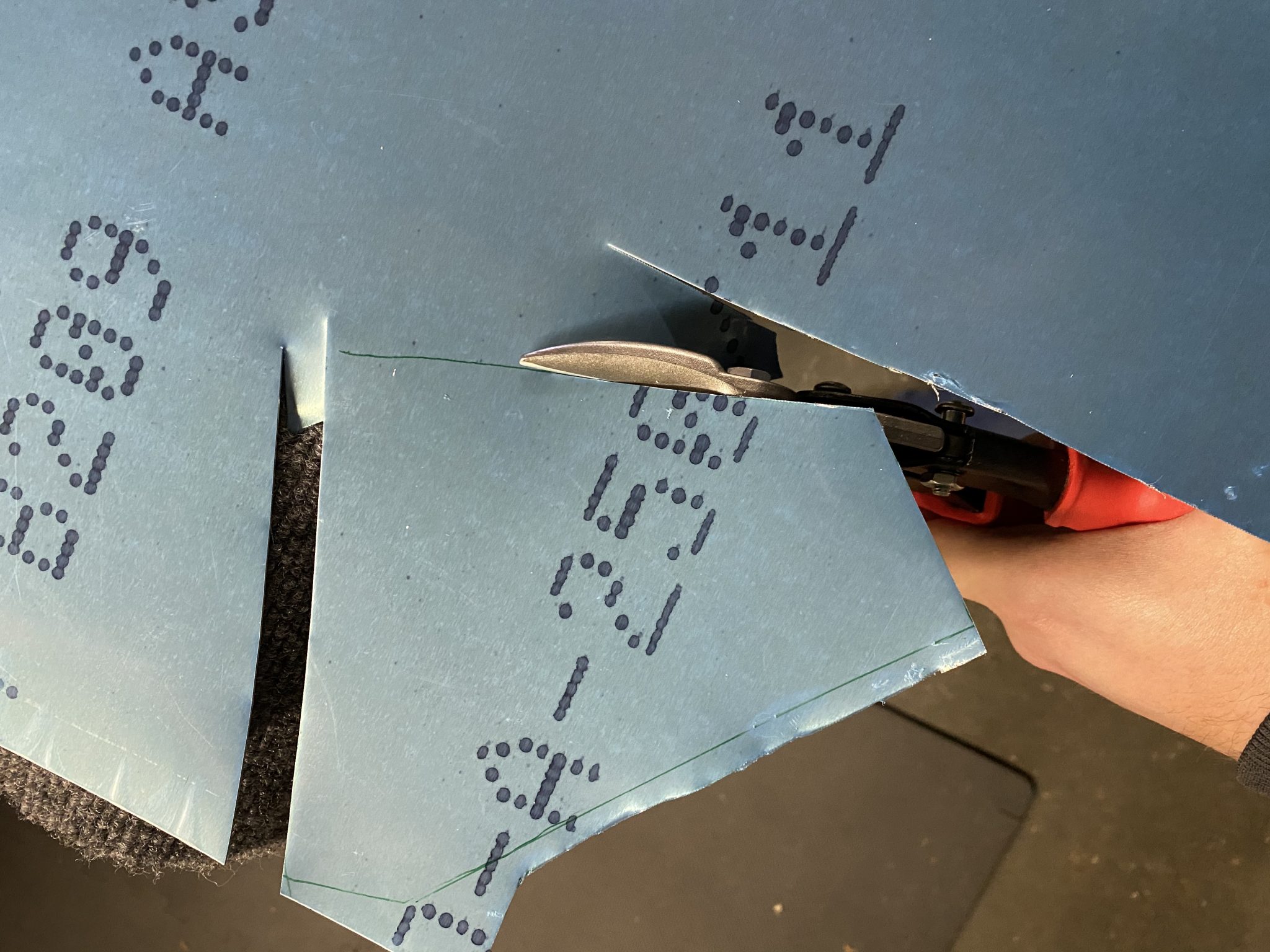
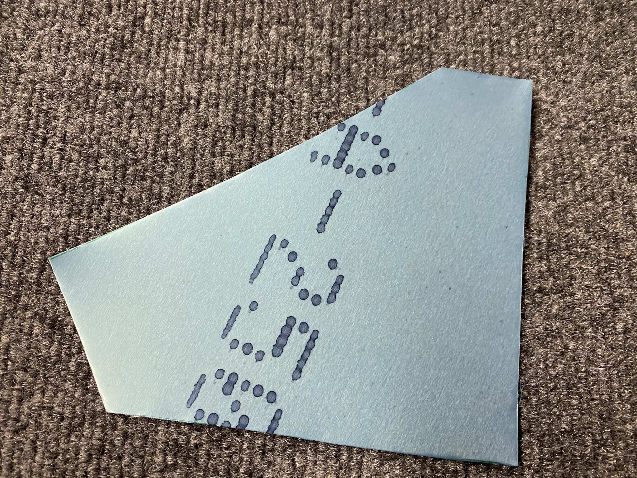
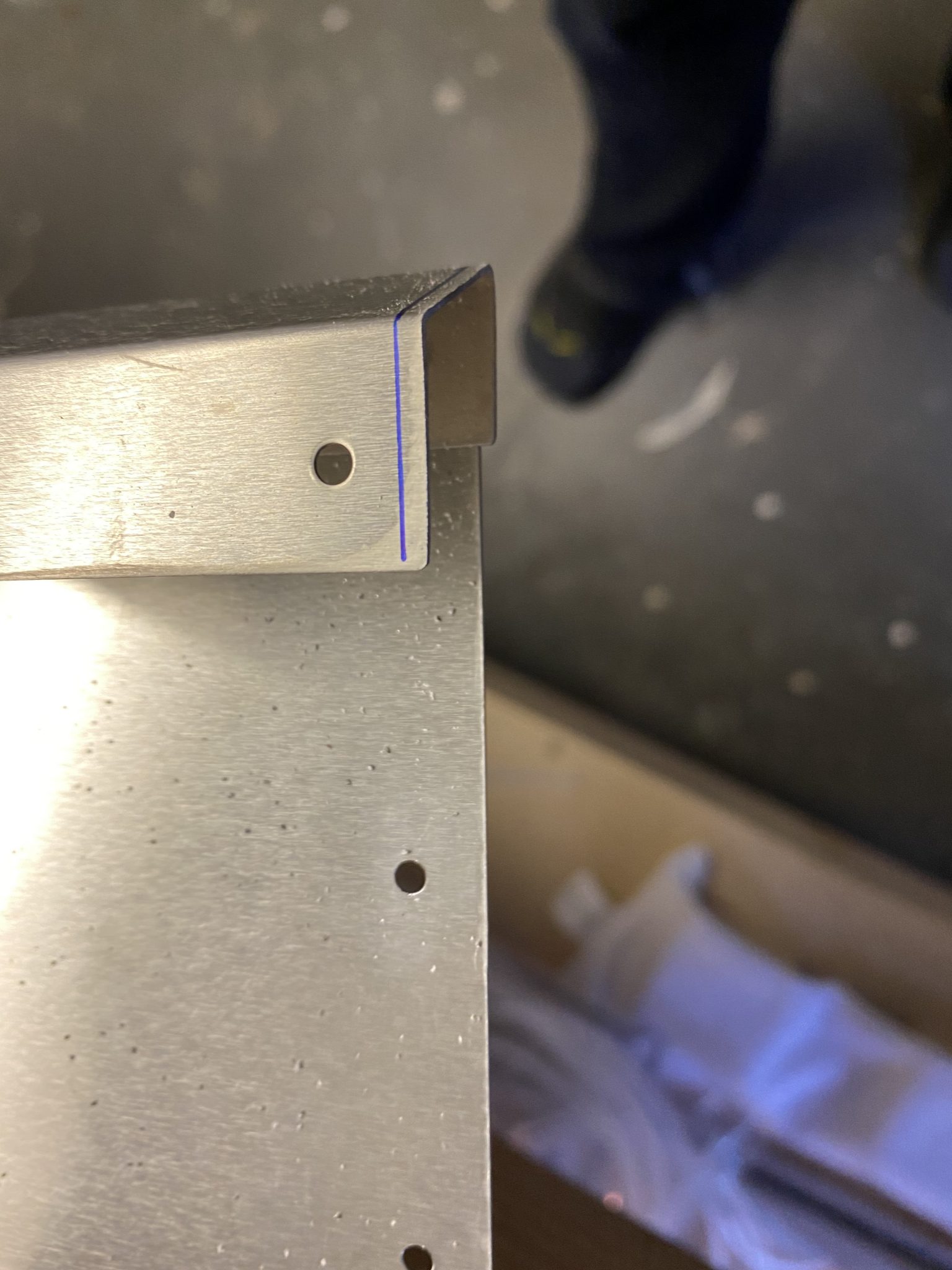
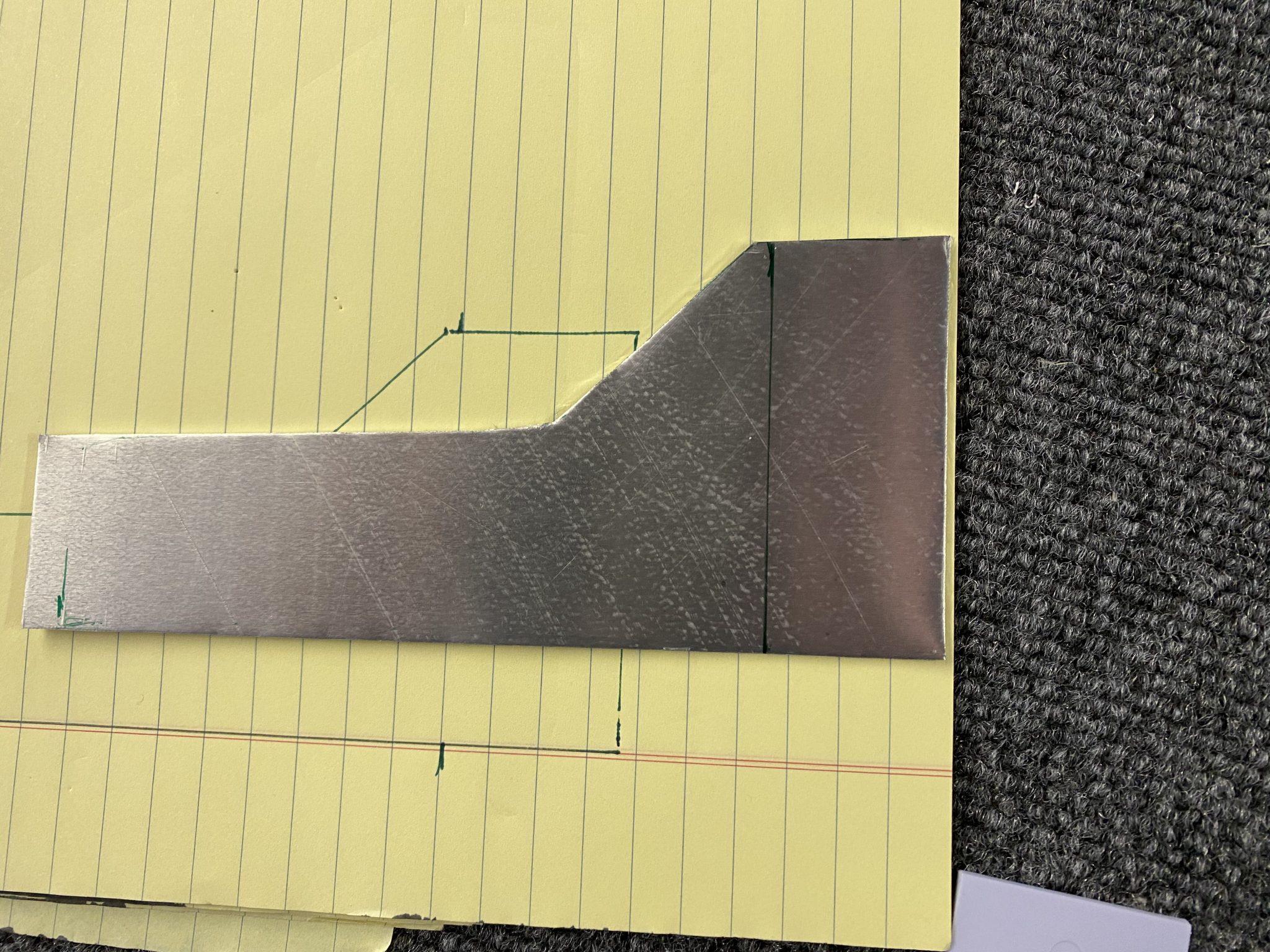
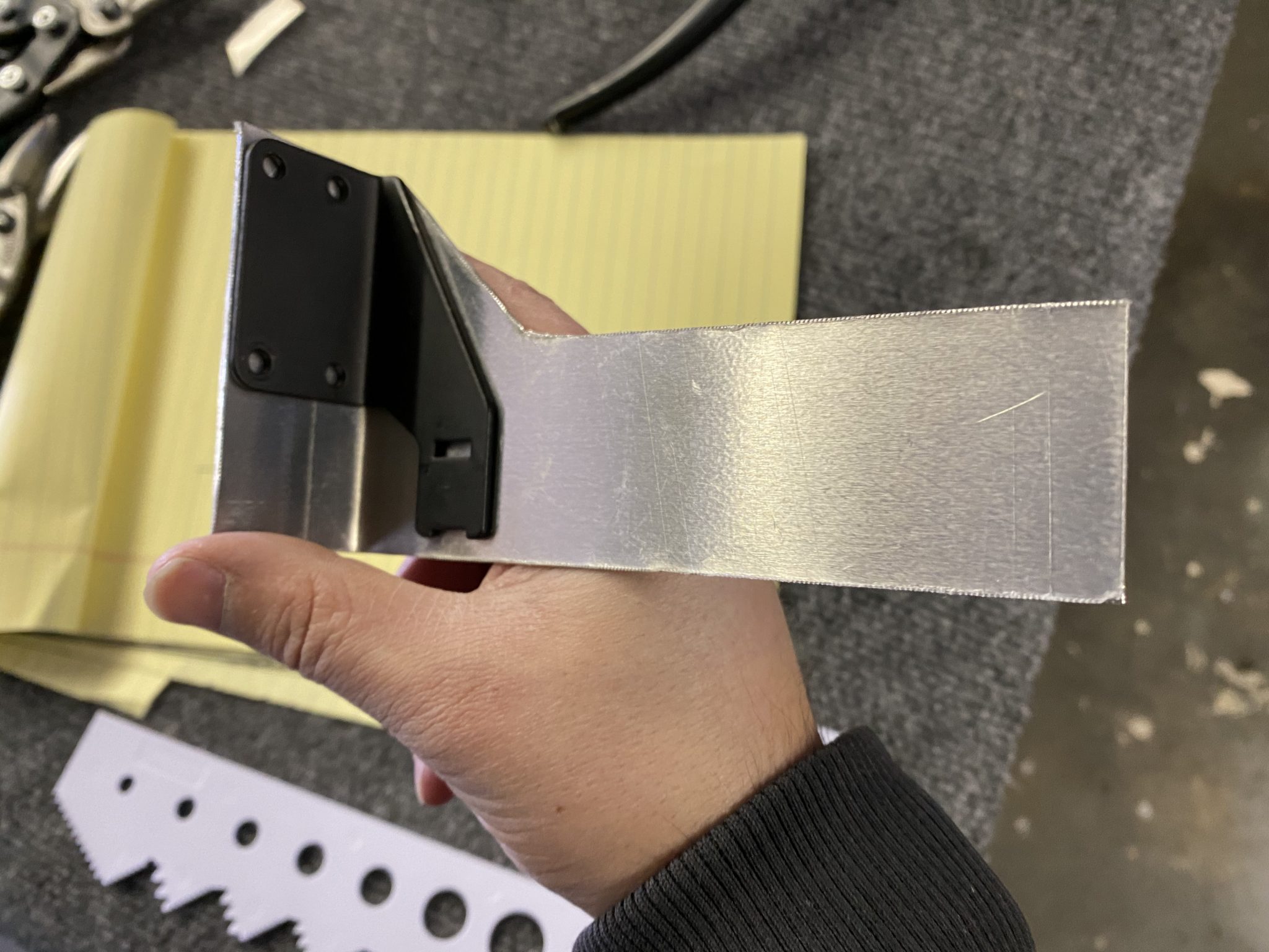
Just like the standard bracket that would usually hold the bowden cable, I designed the bracket to mount into the heater valve unit. So I added the size of the screw mount portion of the original bracket to my cardboard bracket part.

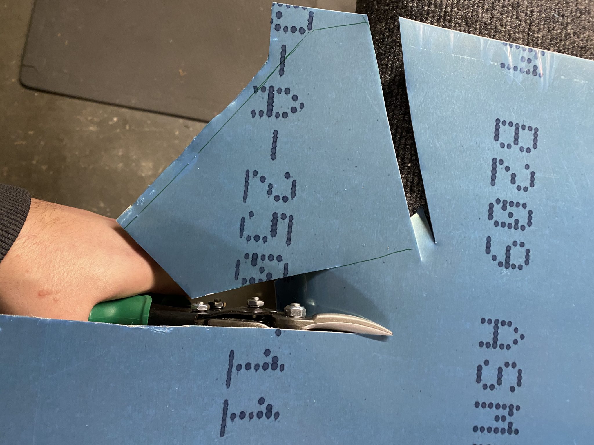
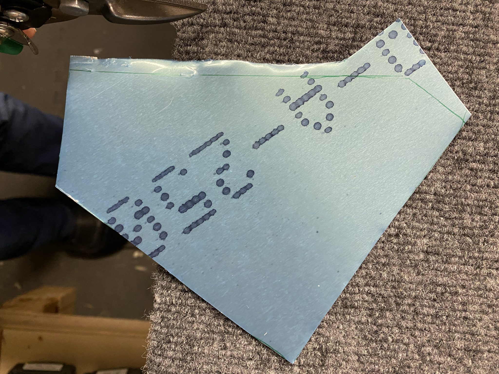
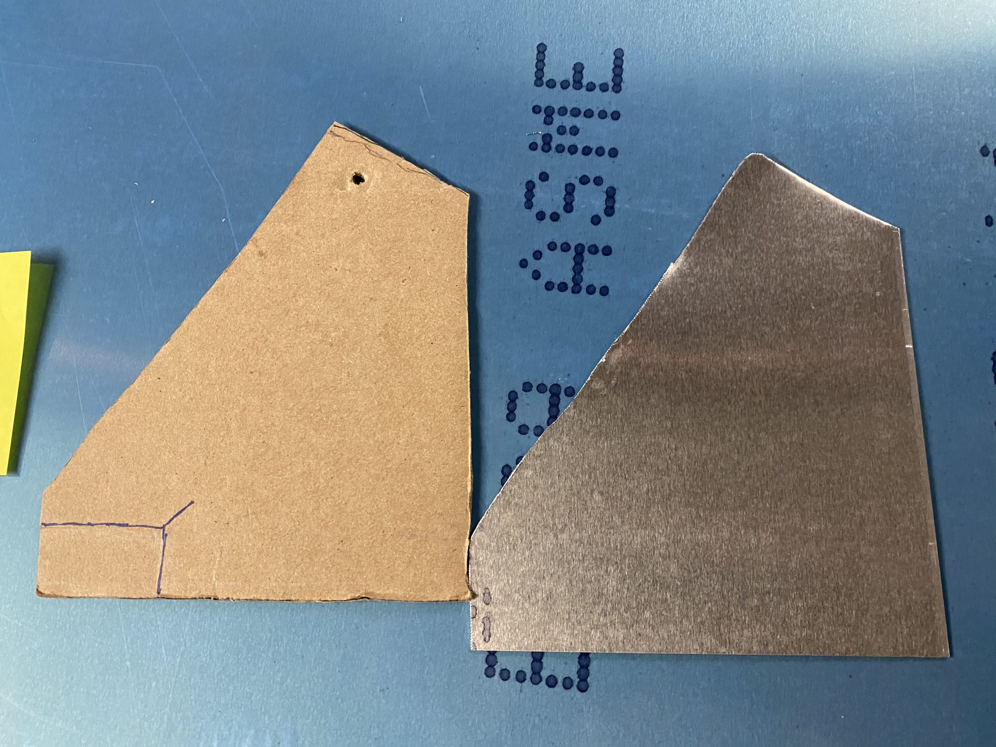
With the outline made, I got out the aviation snips and started cutting out the bracket.
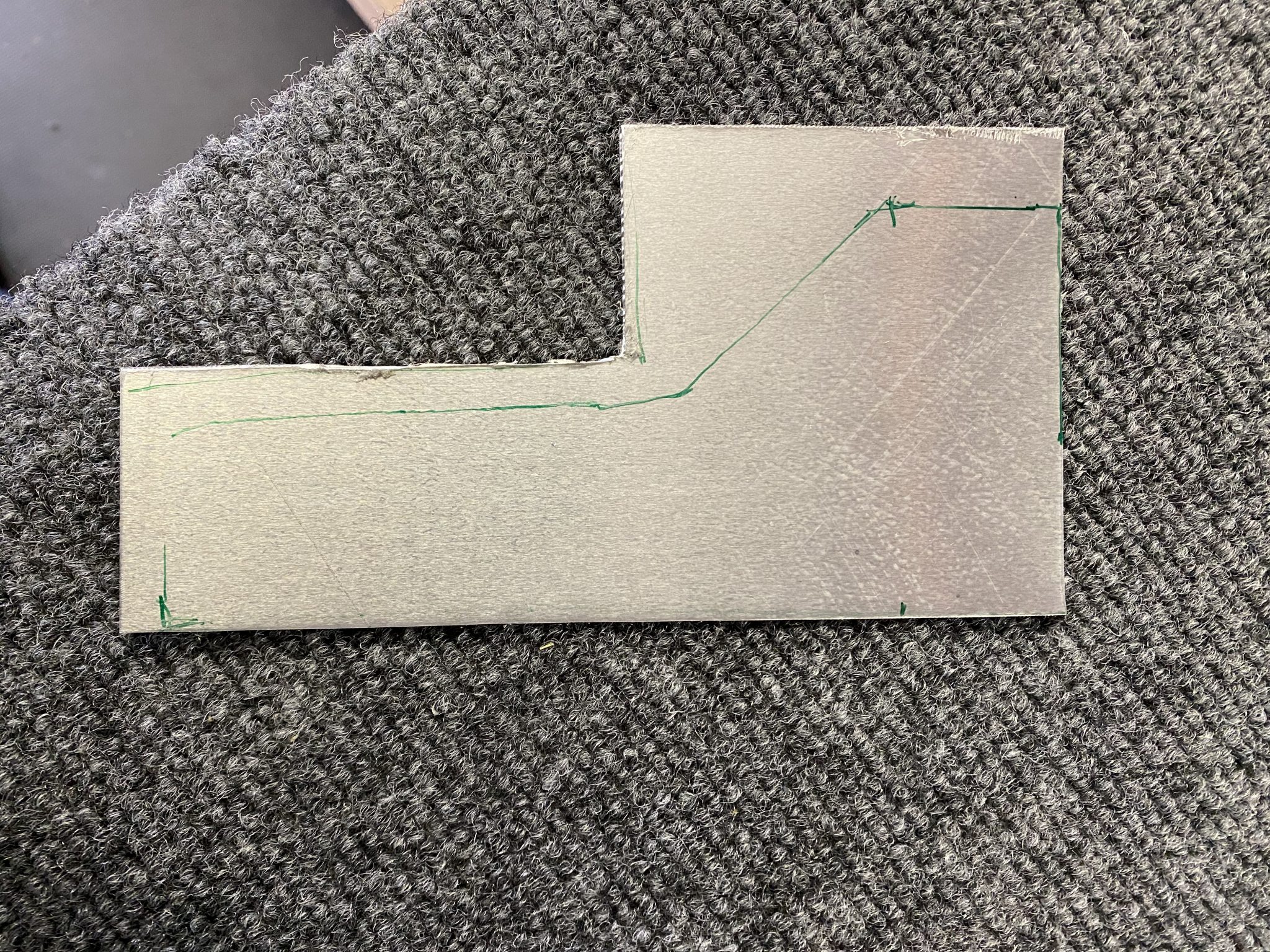
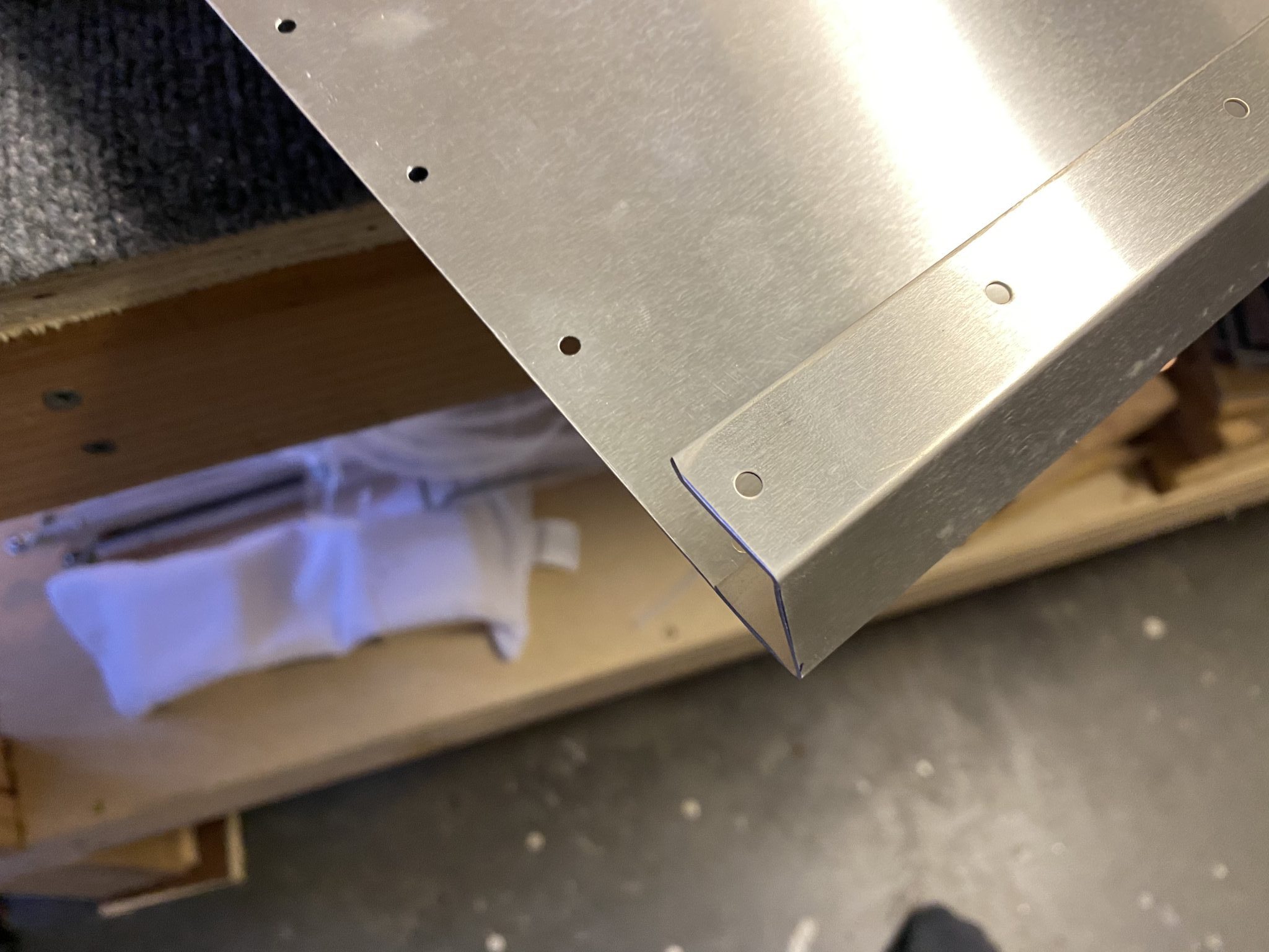
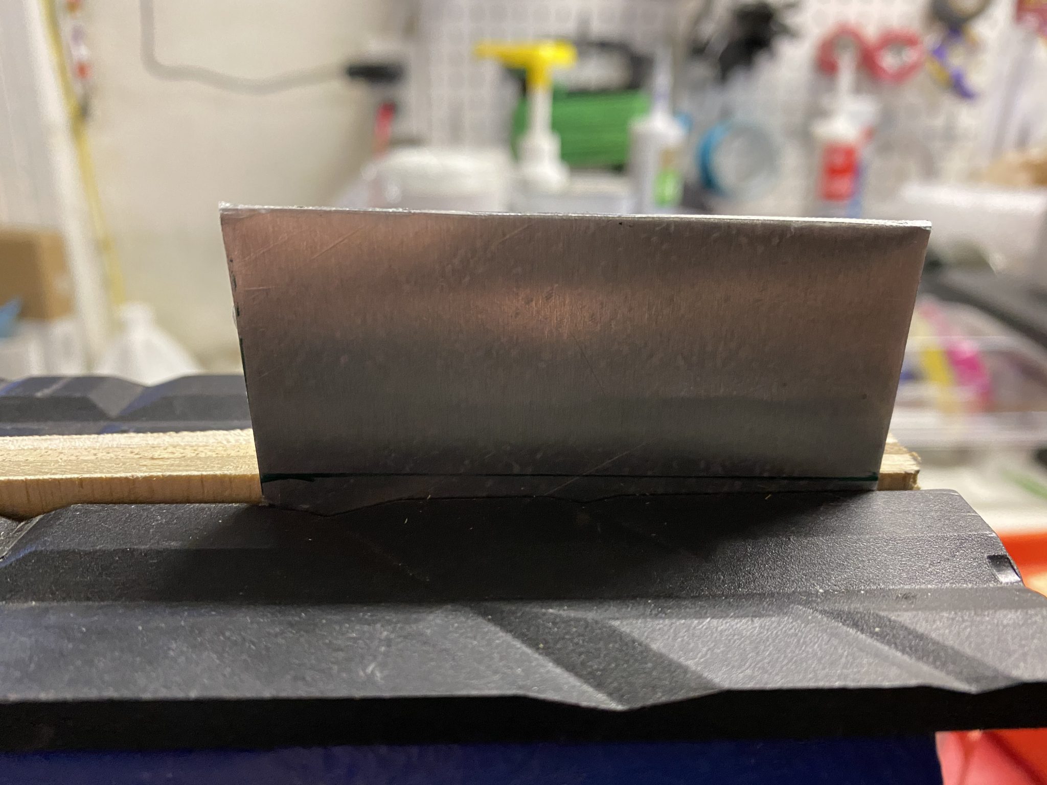
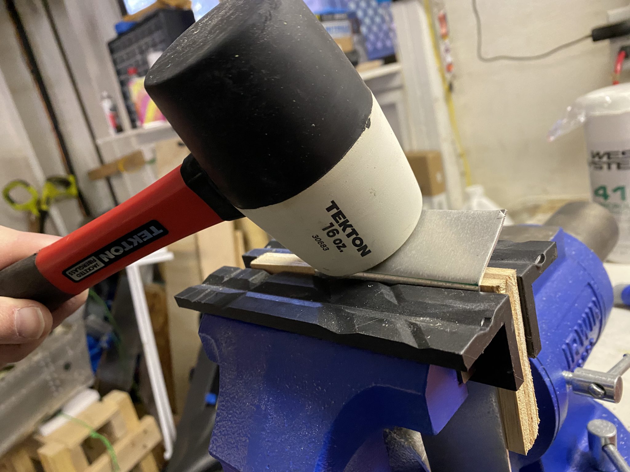
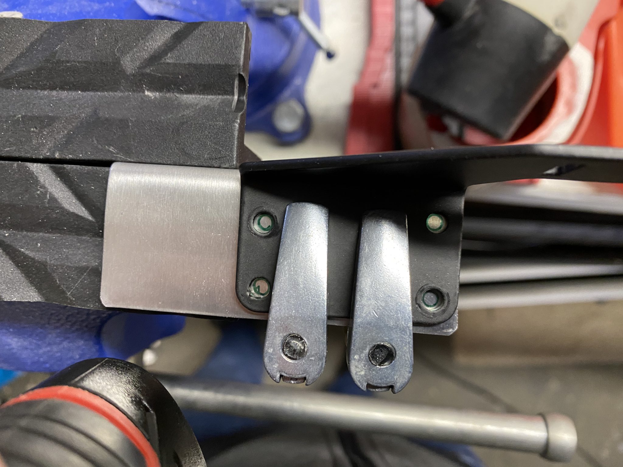
Next step, releasing some tension. To make the bend, I mounted the bracket along the bend line in my bench vise. And then gave it some gentle (read strong) taps with the rubber mallet to form the bend.
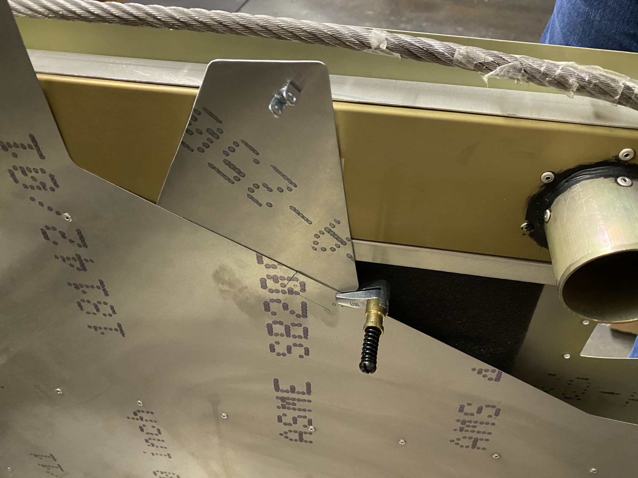
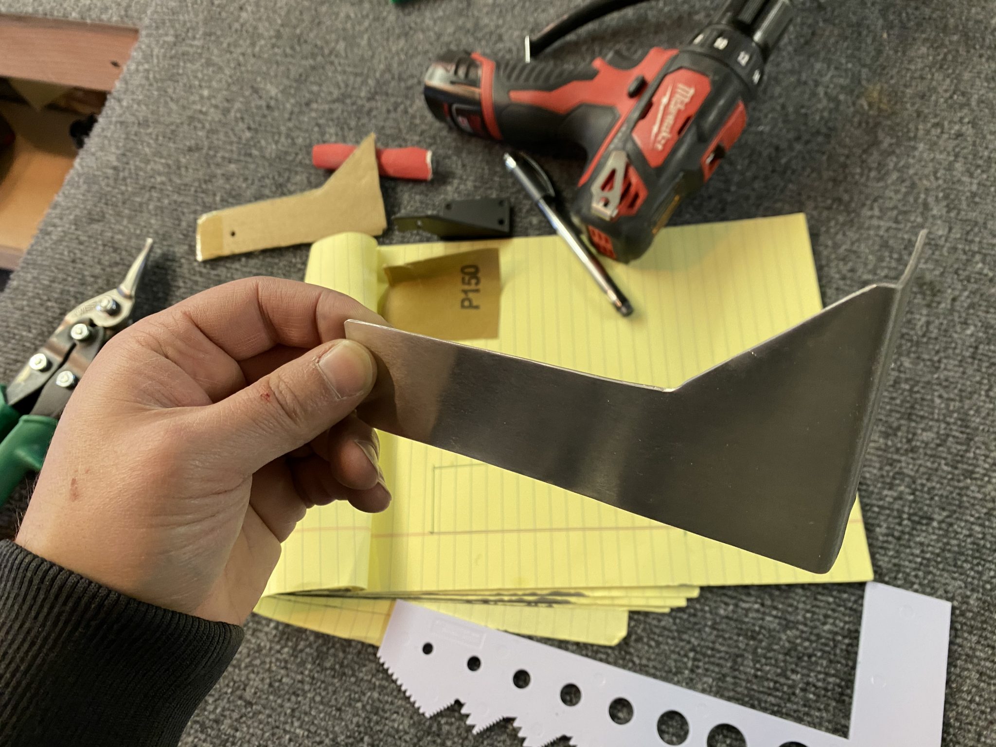
And here it is, a nicely formed 90 degree bend.
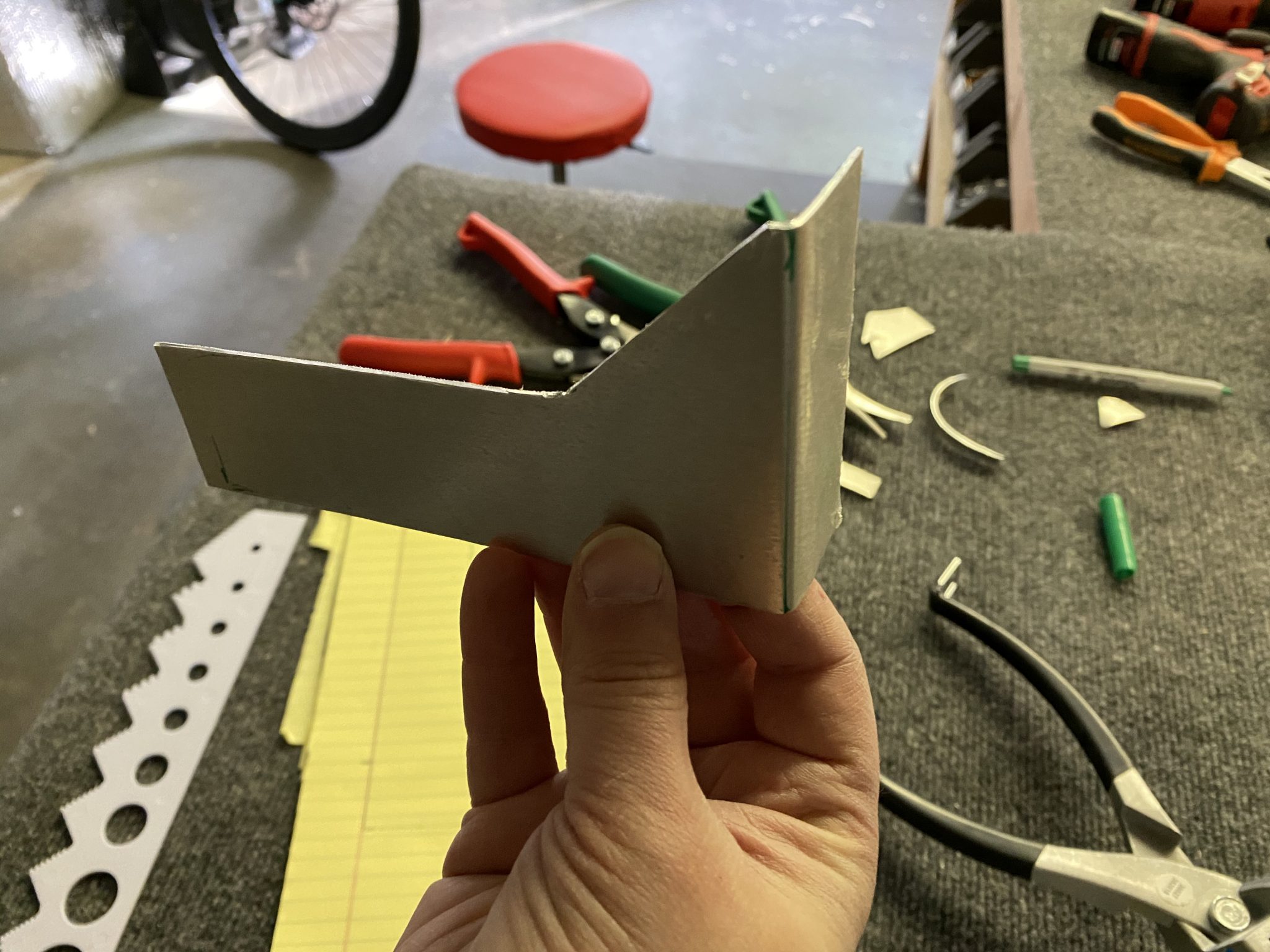
Next I deburred all the edges and rounded out the corners.
And then I match-drilled the holes to mount the bracket to the heater valve using the original bracket.
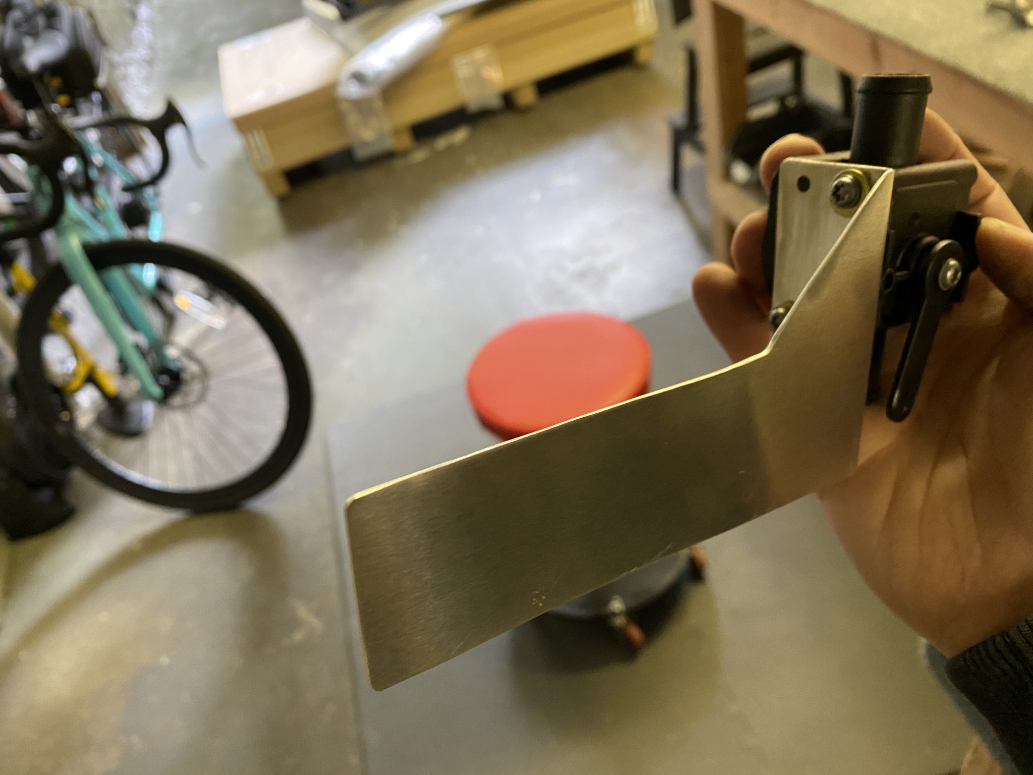
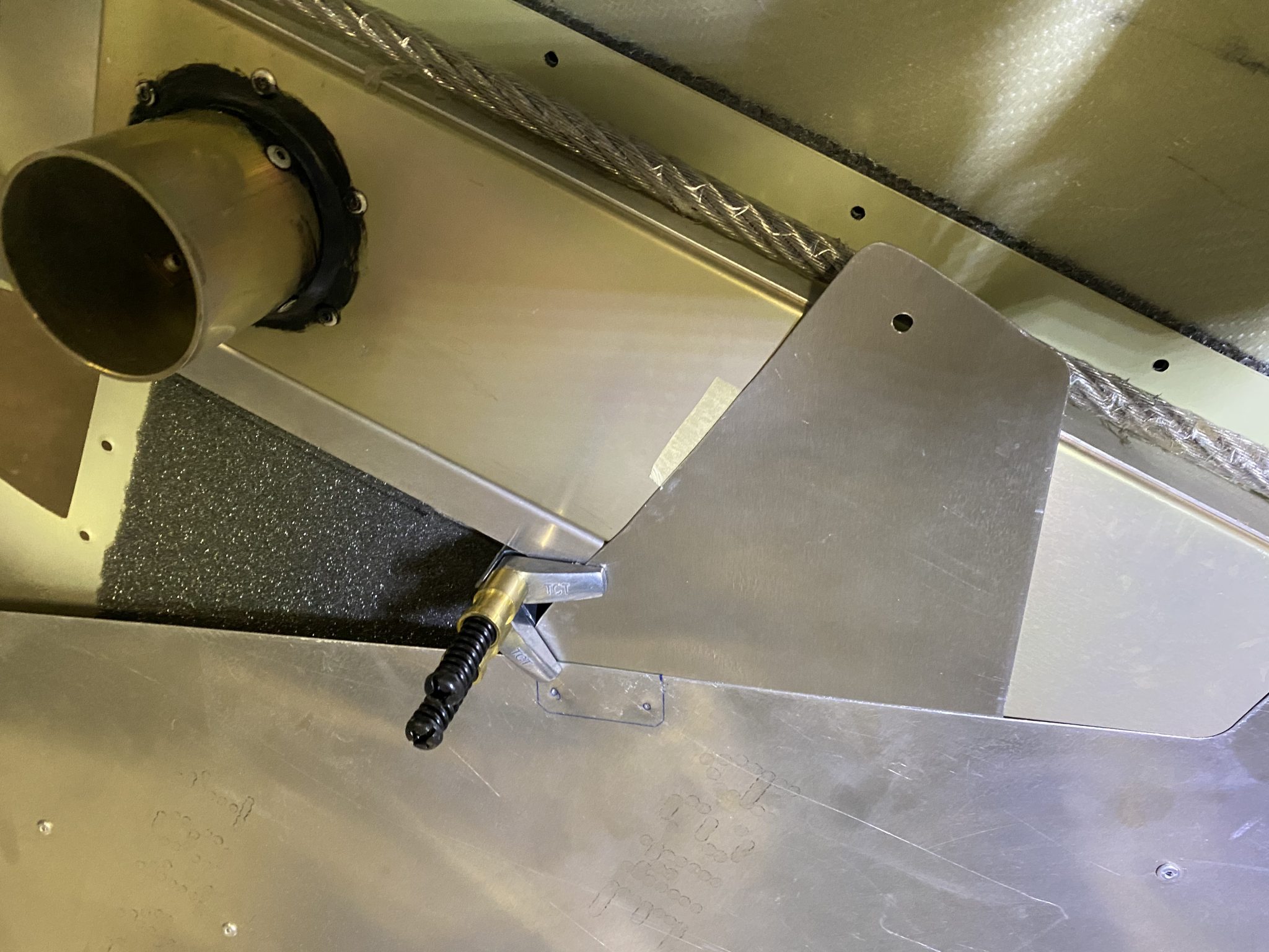
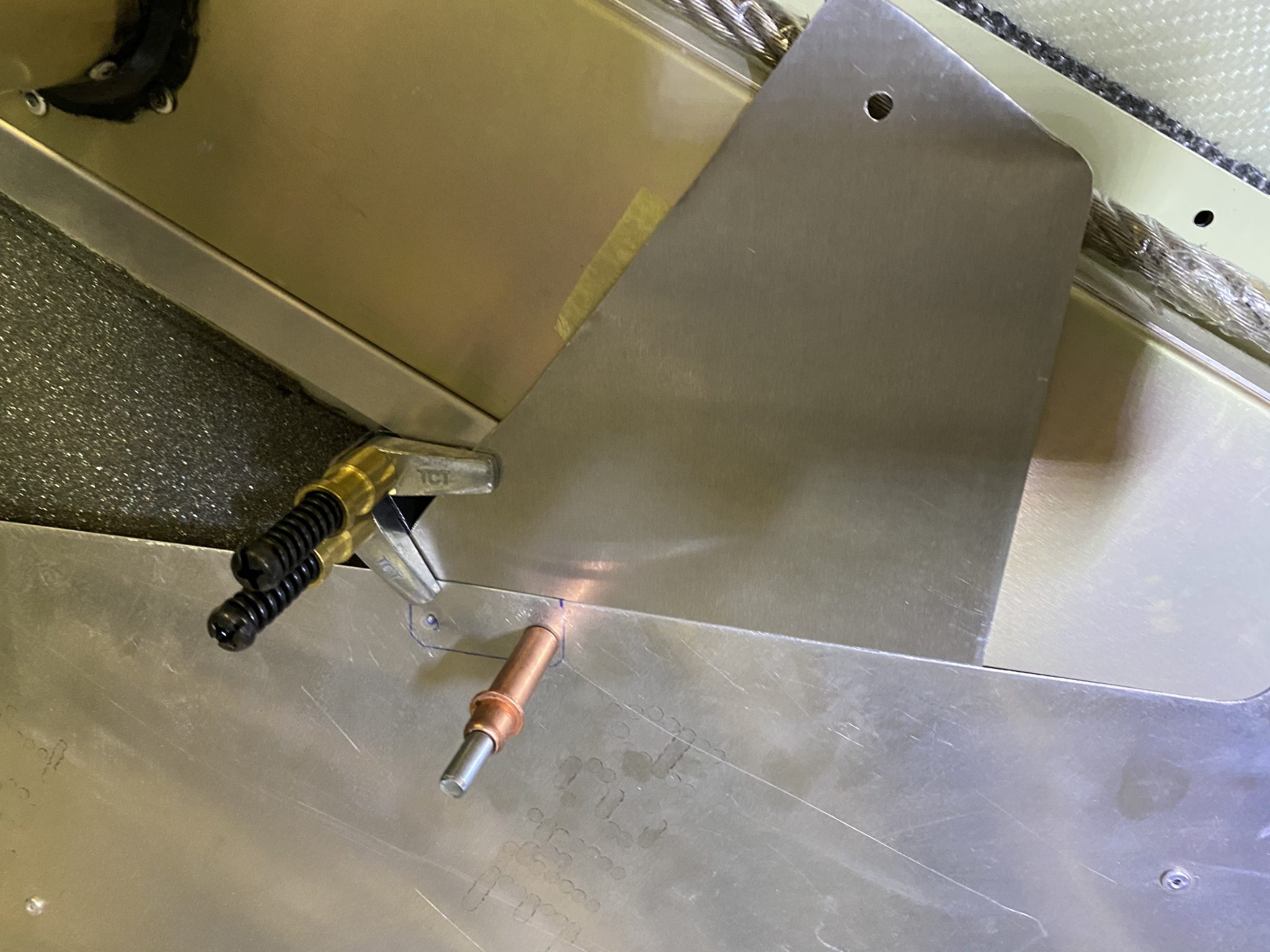
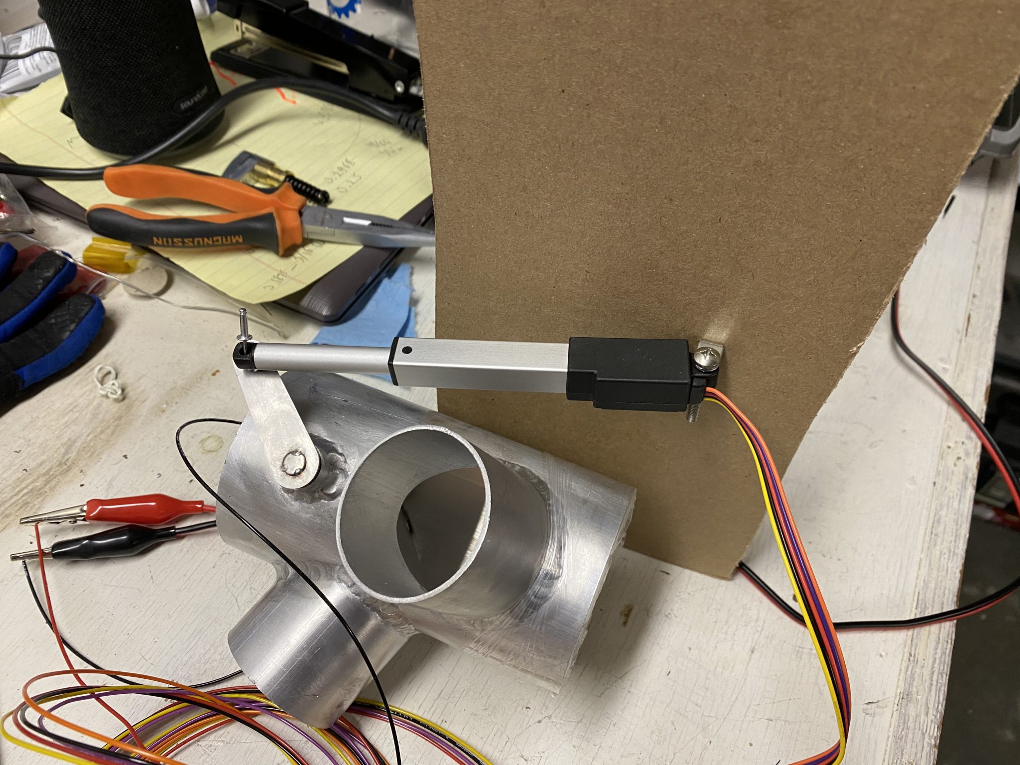
Finally, time to mount the servo to the new bracket. Quick test fitting with a clamp to get the travel distance right.
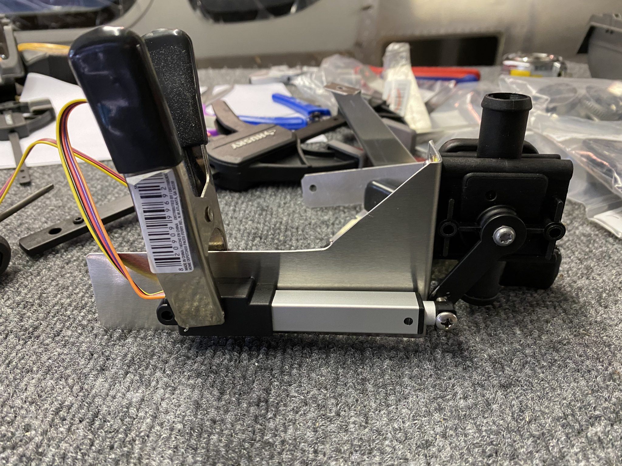
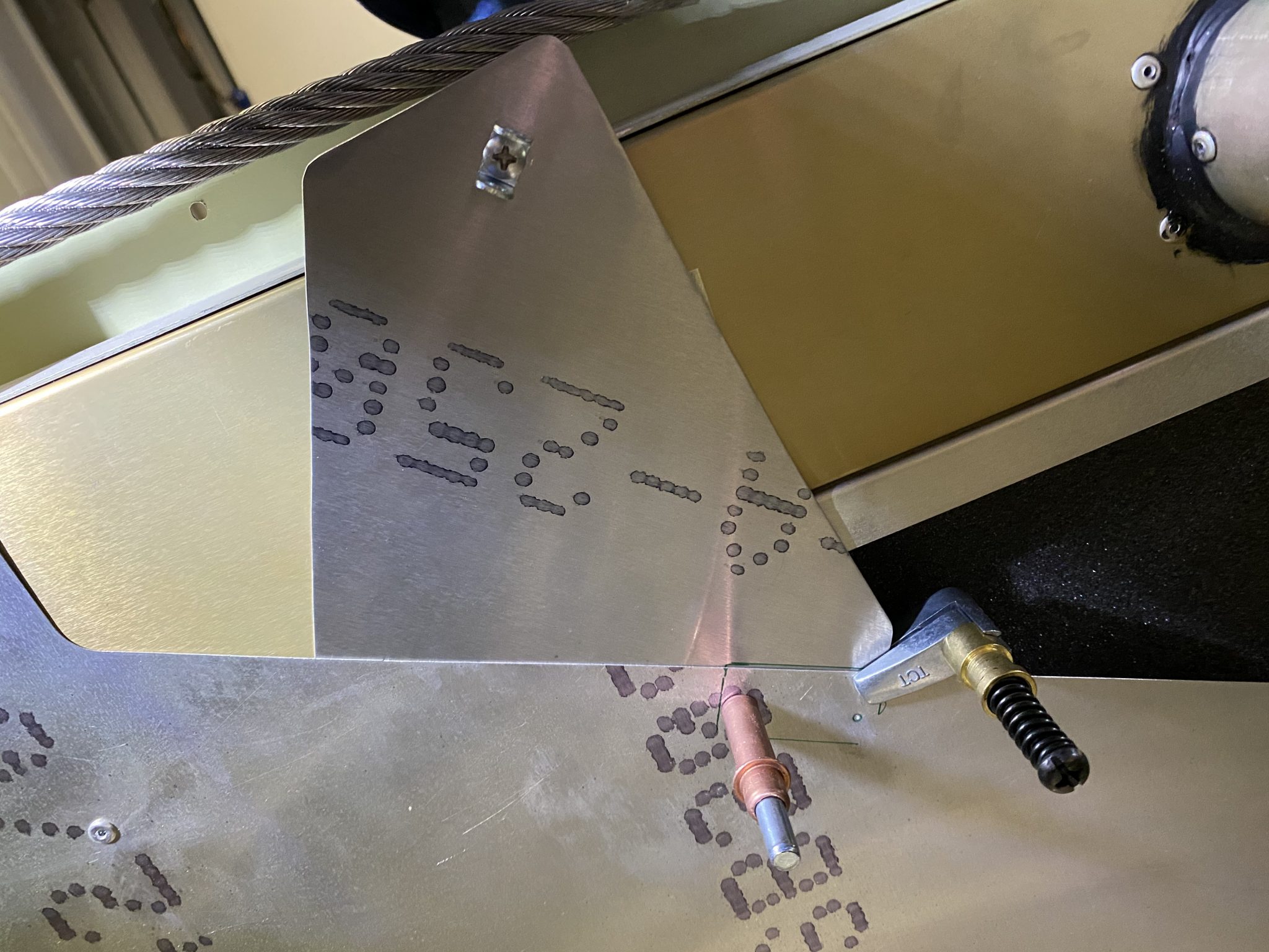
And then I drilled and mounted it to the bracket.
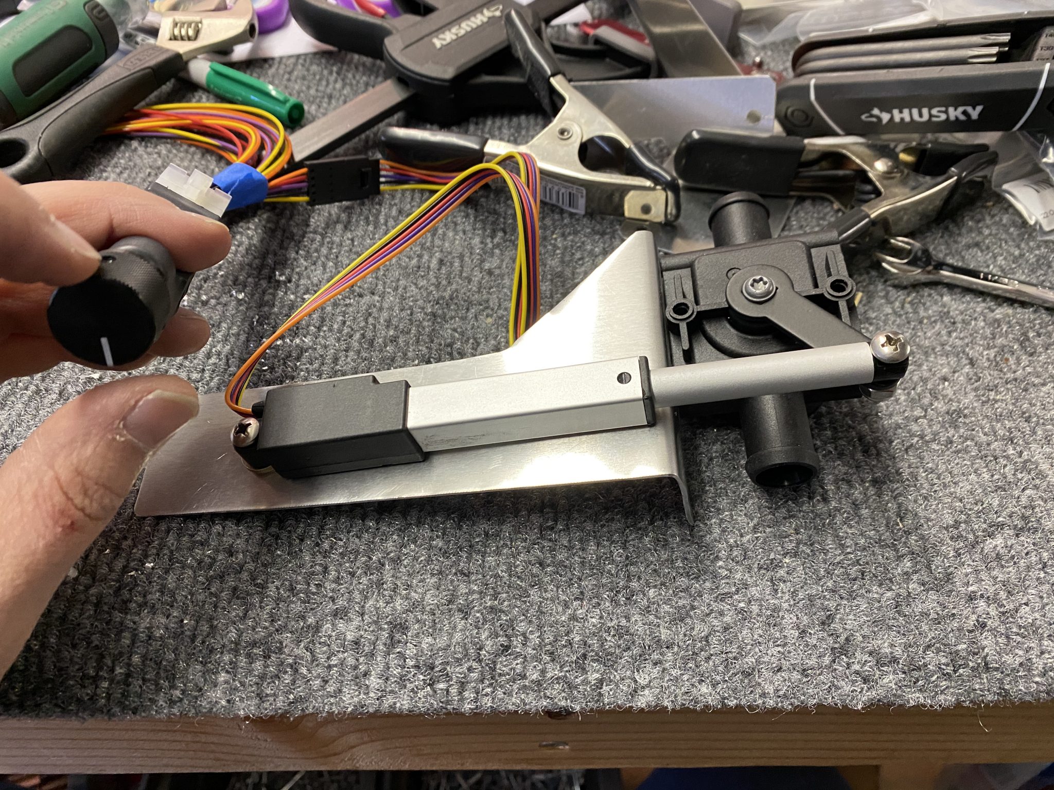
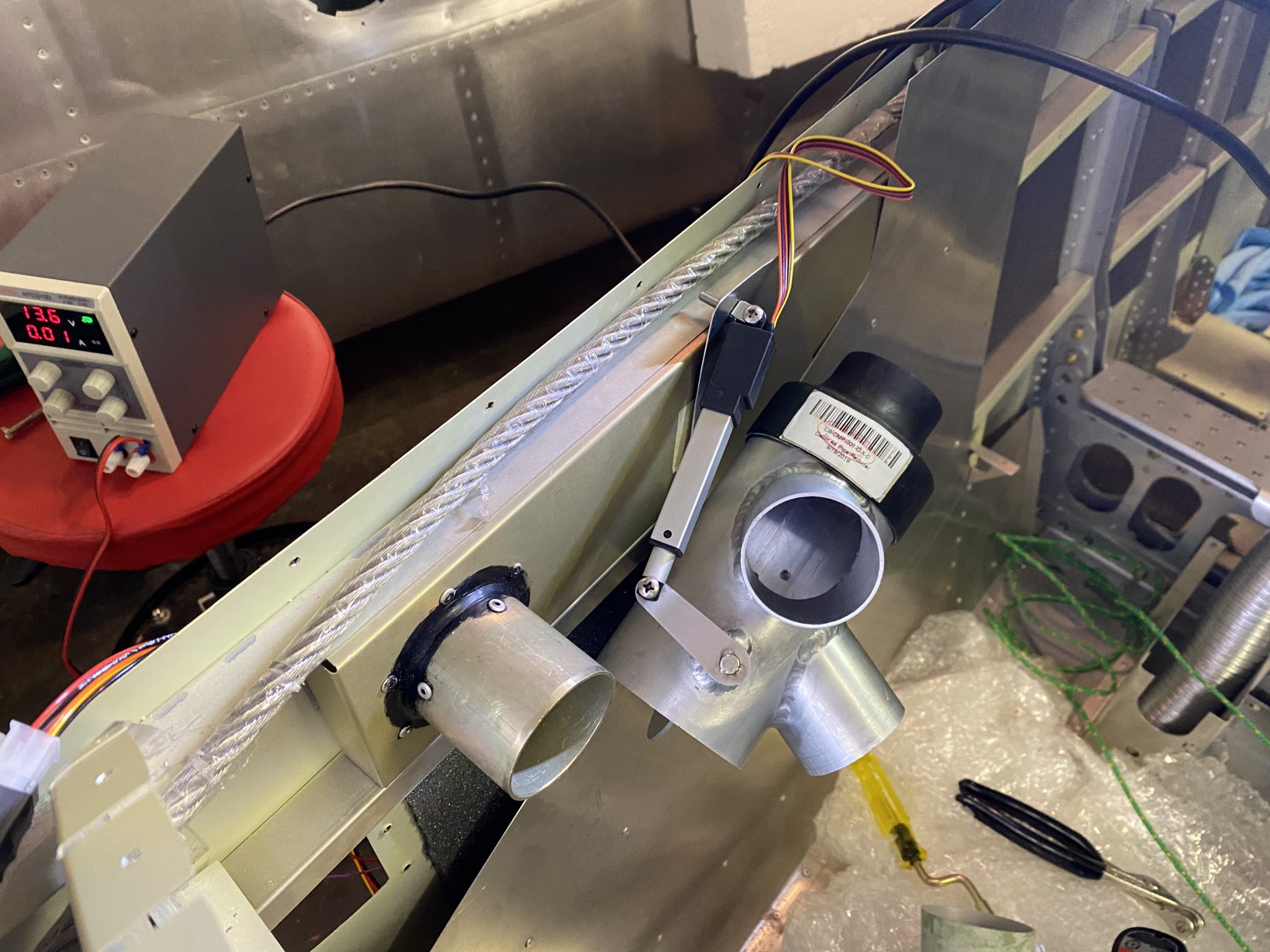
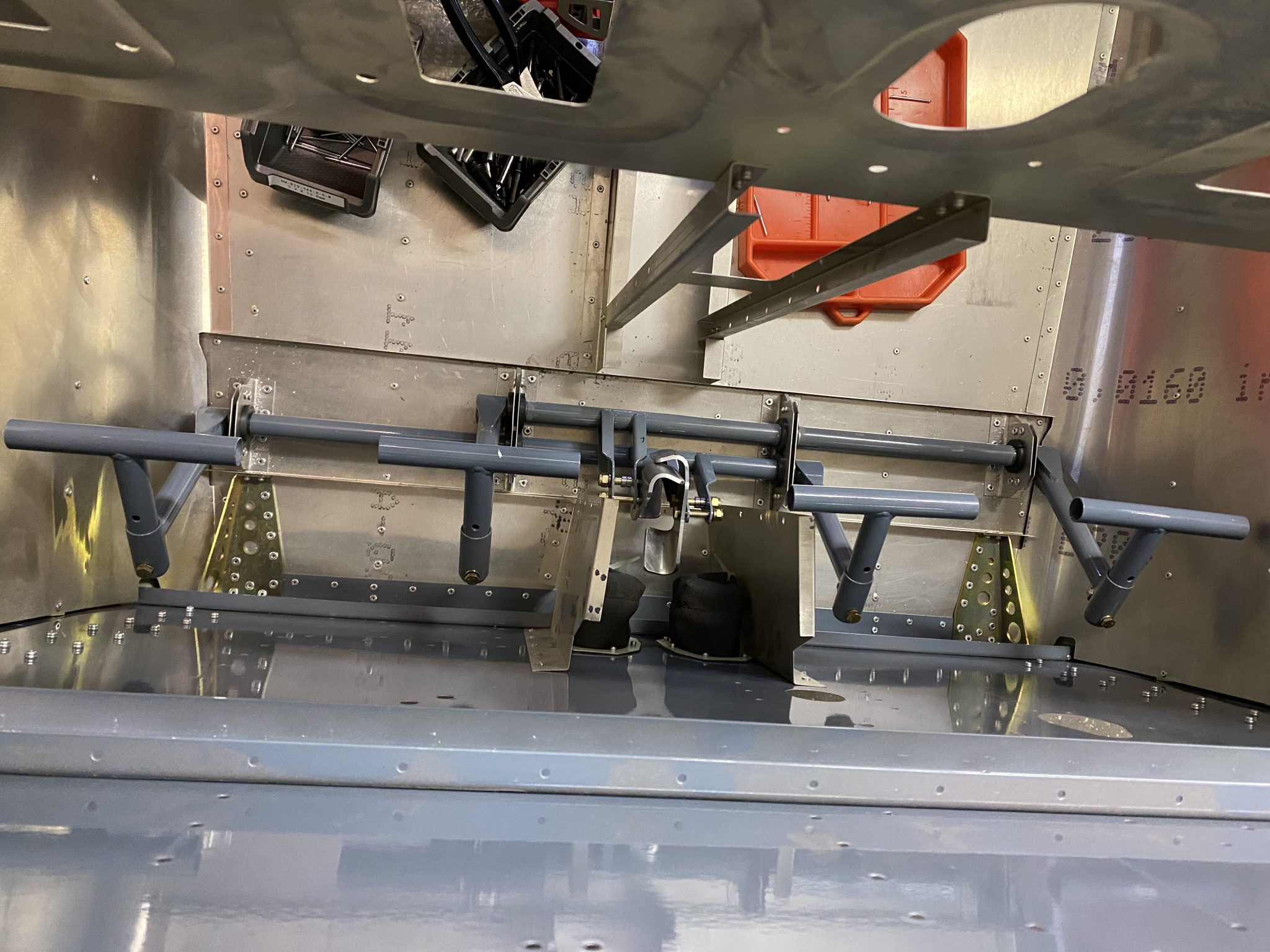
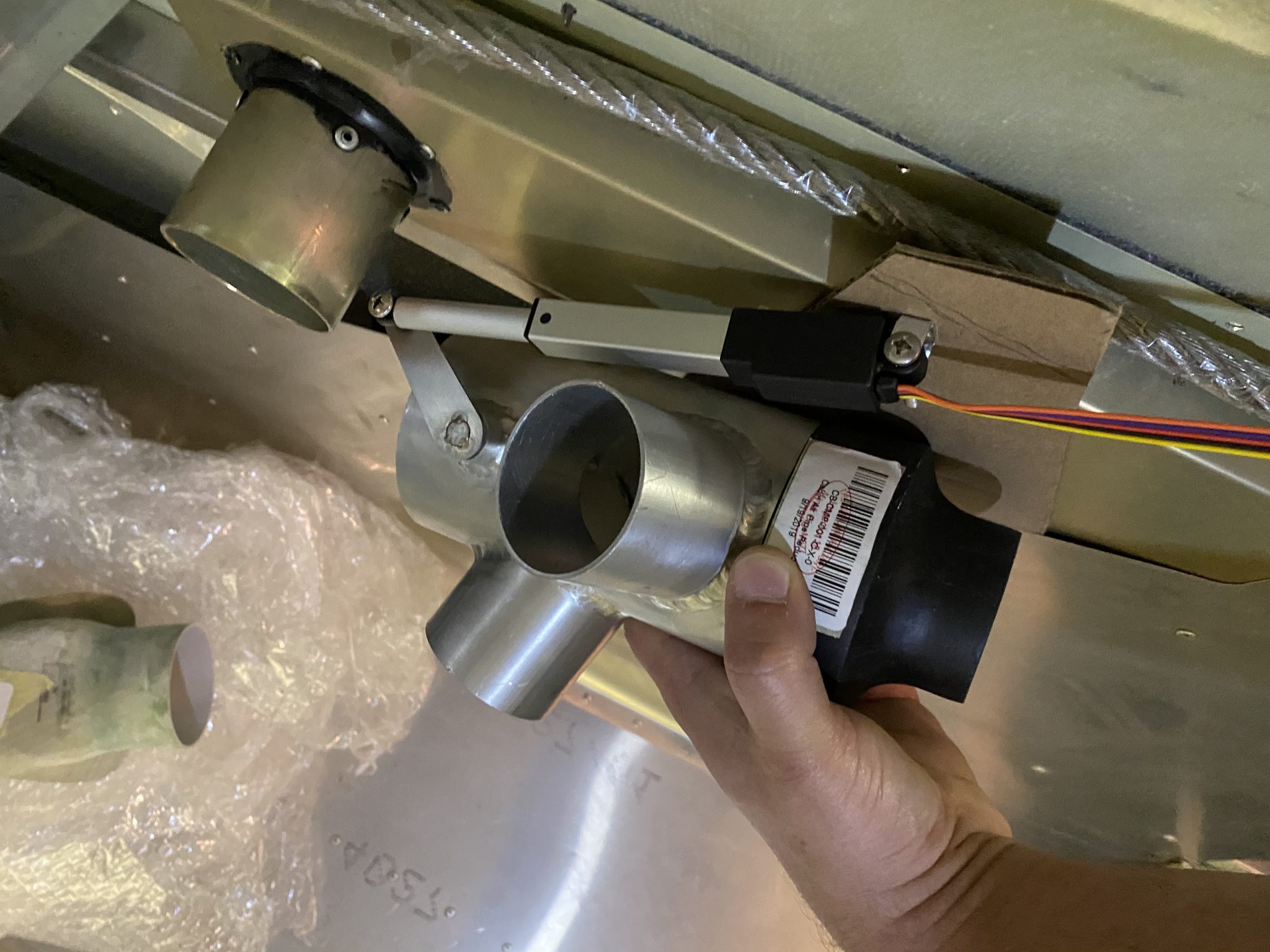
And here it is in action: