
I got inspired to make a small crafty project after seeing someone post about it on reddit and showing it to my friend who said we can make one together.
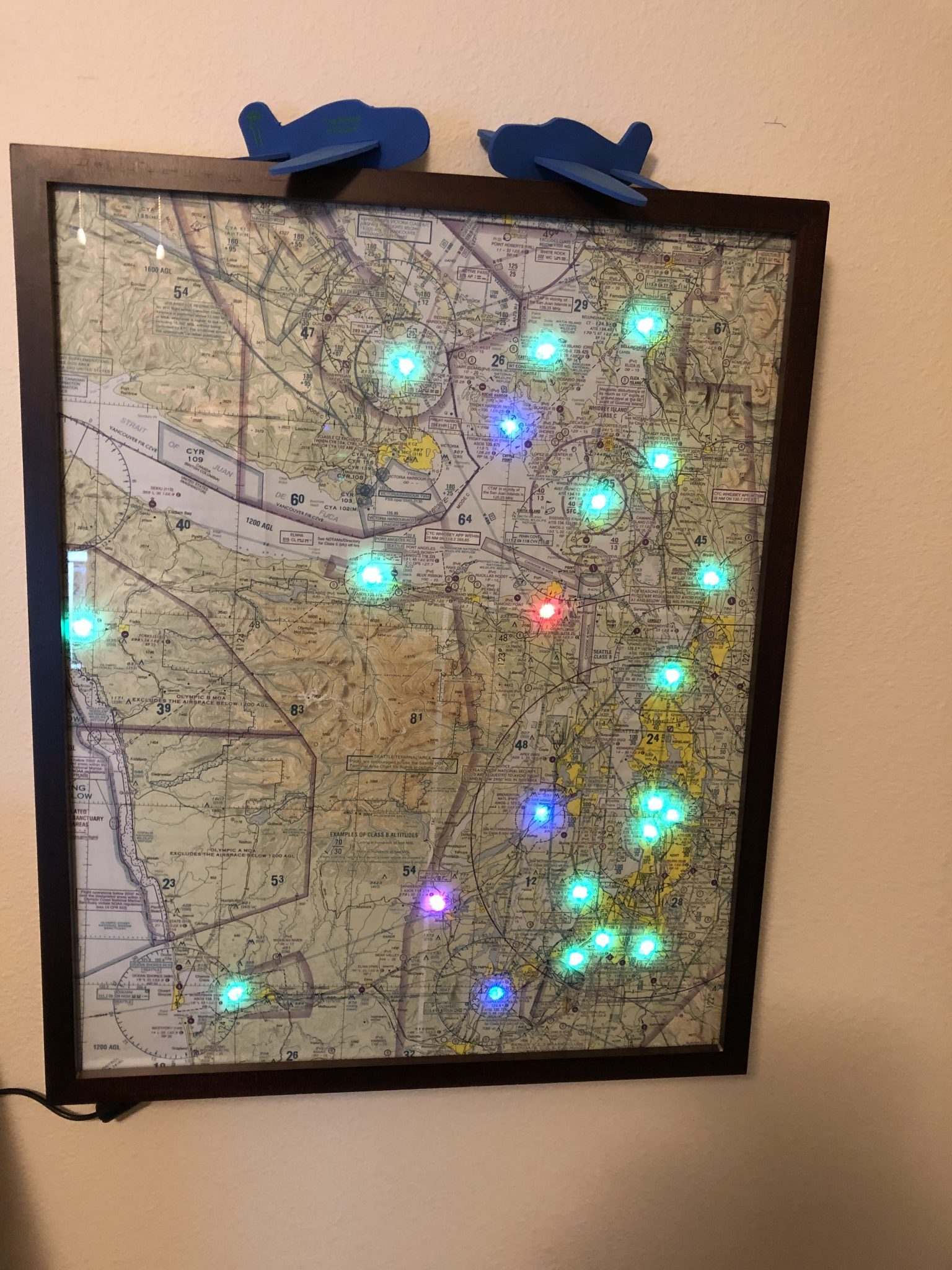
We did a bit more research and because I’ve made some projects with Raspberry Pi before, we decided to go that route. Here’s a picture of the finished project:
Supplies needed
Here’s a list of the things you will need:
- Raspberry Pi Zero W – This kit comes with a nice case, the pin headers and a power supply, but you could also buy those separate.
- Micro SD Card to install Rasperry Pi OS Lite
- WS2811 addressable LEDs
- Wires to connect Raspberry Pi to LEDs
- Sectional Chart
- Soldering Iron to attach the pin headers to the Raspberry Pi
- Foam Board to glue LEDs into from your local crafts or stationary store
- Shadow Box frame (in our case we used a 16 x 20 inch frame)
- Some transparent sheet to transfer the location of the airports from your sectional to the board for drilling (we cut up and taped together some sheet protectors we had around)
- Glue stick to attach the sectional chart onto board
- Glue gun (or super glue would probably also work) to affix the LEDs to the board
Plotting your chart area
Unless you want to make your own frame, the dimensions of your project will be limited by what size shadow box frame you can easily purchase. The simplest size is 16 x 20 inch frames, so I used that as a guide of the area to size out.
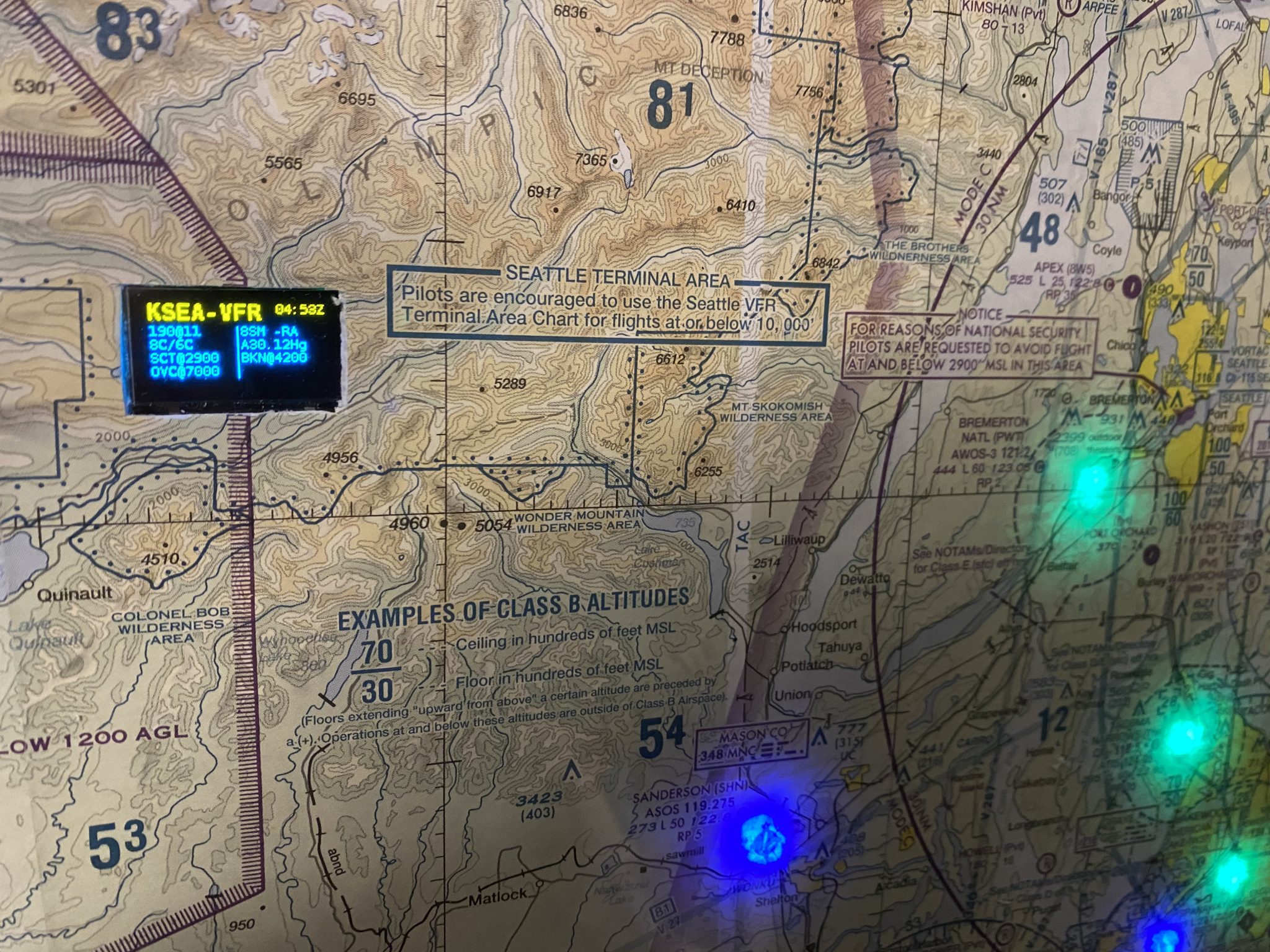
This worked out great for the Puget Sound Area to cover the airports from Bellingham in the north to Olympia in the South and Hoquiam and Quillayute on the coast using my old expired sectional chart from my private pilot training.

To light up the airports with the flight category, we’re using the data reported from www.aviationweather.gov so we checked the airports we want to highlight via the API to ensure they are reporting data.
After we were satisfied with the area, we created a 16 x 20 inch transparent sheet by cutting up some sheet protectors and taping them together and then overlaying them onto the area and marking down the airports so we could transfer the locations onto the back of foam board for the LEDs to go into.

Software and Wiring
Since the project is pretty simple, we used a Raspberry Pi Zero W, which has WIFI built in and can run the code to download the weather data using the above mentioned web API to pull the weather for all the airports in one go.
For the code, I’ve started by looking at some of the other projects people have done and the NeoPixel documentation for python.
We wrote an updated and optimized script and published it on Github, along with the instructions to set it up.
We ended up with a total of 22 lit up LEDs, so we wired it directly to the Raspberry as shown here. Before attaching the wires to the Raspberry headers, I soldered the header strip onto the Raspberry so it creates a good connection.
![]()
Here’s a picture of the wiring while I was testing out the code. I was using a breadboard while doing this since it made it easier to disconnect the wires during testing.
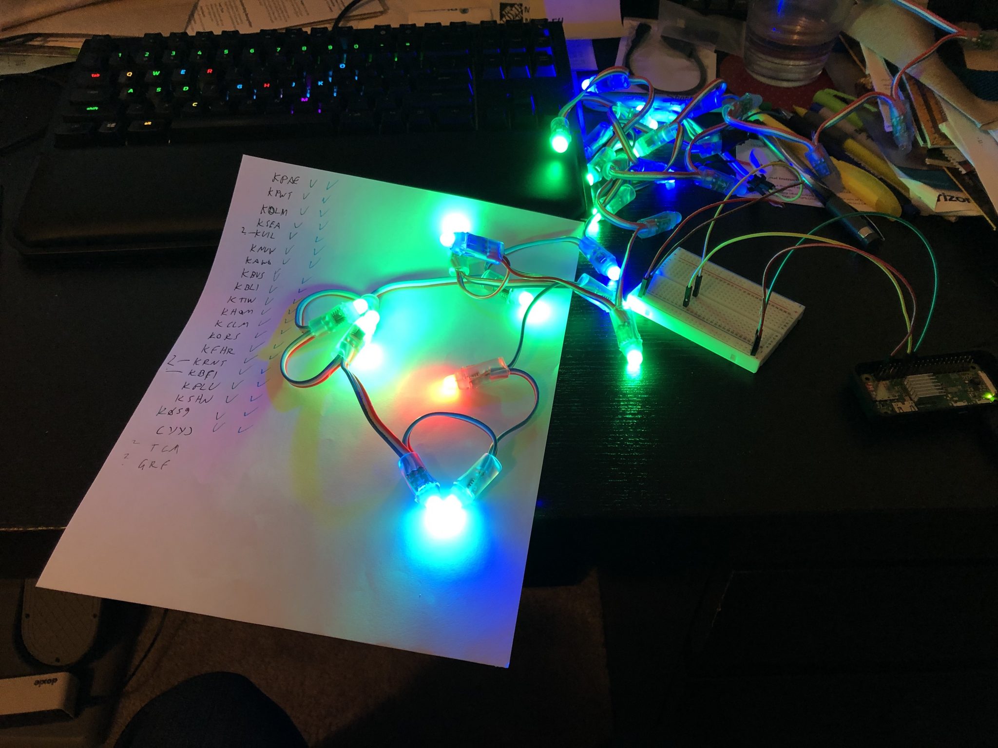
To finalize the order of the LEDs you will need to arrange them on the board and make changes to the airport list accordingly.
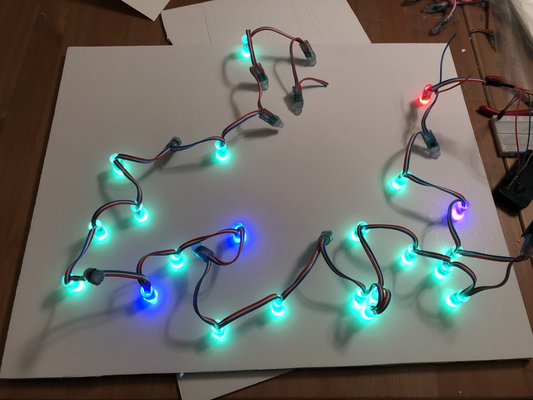
Another important note is to test the LEDs for all the colors in case there is a bad one, in our case the 5th LED couldn’t show RED light, so we skipped over that one.
The easiest way to test this once you’ve installed the software is to just manually control the colors of the LEDs by opening the python3 console:
sudo python3
Then entering the following to light up 30 LEDs at once (if you are using more, just replace the number below):
import board
import neopixel
pixels = neopixel.NeoPixel(board.D18, 30)
pixels.fill((0,255,0))
This will light up all LEDs in red, if you see a bad one, mark it with some tape so you don’t use it for an airport.
Repeat the step for green:
pixels.fill((255,0,0))
Blue:
pixels.fill((0,0,255))
Purple:
pixels.fill((0,125,125))
Once you’re done you can turn off the lights by typing
pixels.deinit()
and then pressing CTRL+Z to exit the python console.
Board Assembly
Once we figured out the software portion and what airports to light up it was time to drill some holes in the foam board for the LEDs to go into using the template made earlier.

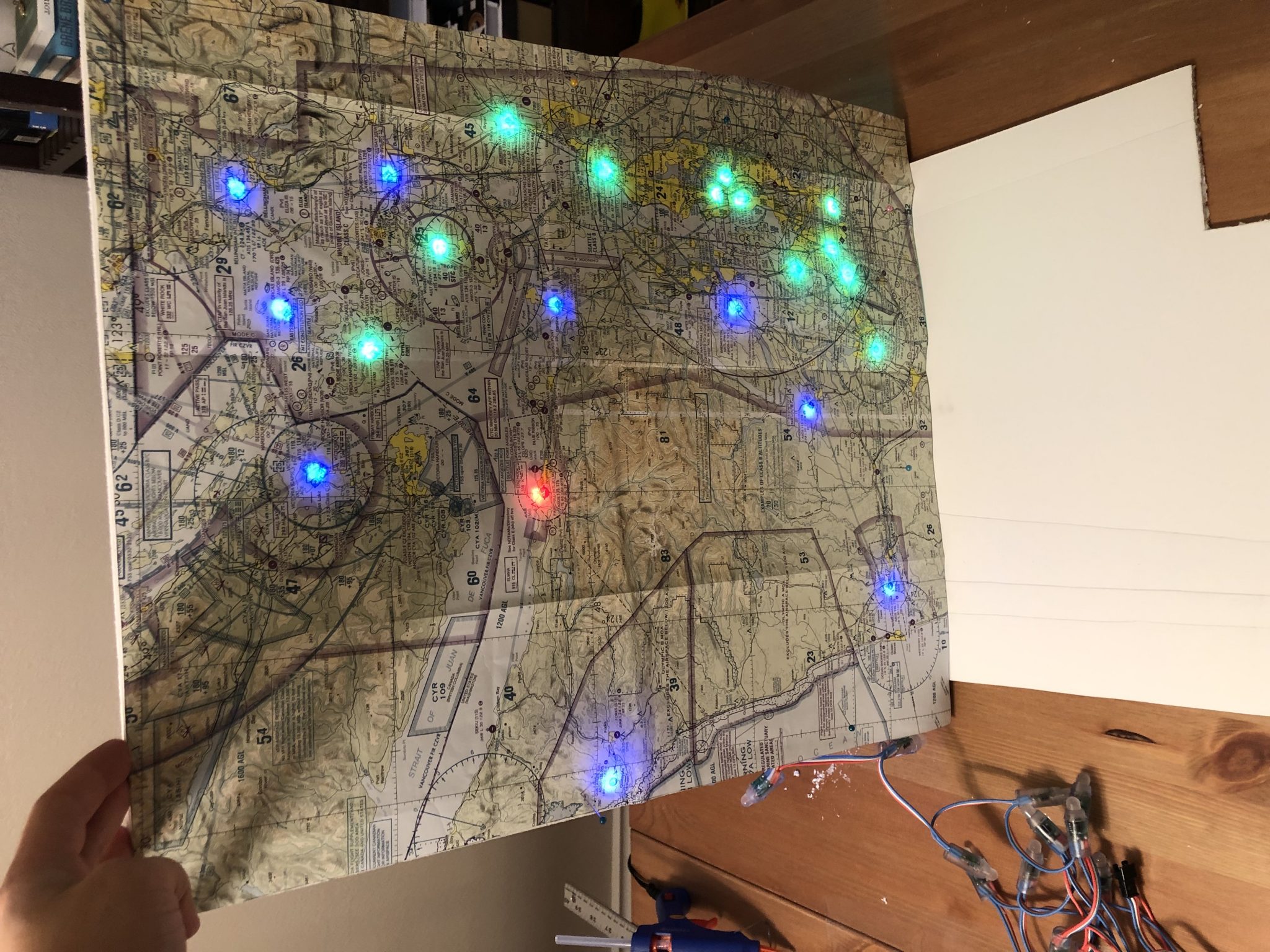
After we had the holes made we tested it by temporarily affixing the sectional chart onto the board and sticking some of the LEDs into the holes and turning on the project, but we found that the LEDs created a lot of light and the LEDs were sticking out a bit, so we decided to double up the foam board, which made the light more defined and allowed the sectional chart to sit flush on the board, so we glued together the two foam boards.
We did a second quick test and pinned the sectional chart onto the board for the first complete light up test:
After that it was time put everything together. we made the final cuts to the chart to fit perfectly onto the board and align with the lights and then glued it to the board using a glue stick.
Then it was time to glue the LEDs onto the board, as you can see from the picture below, some of the LEDs are not lit, one of them because the red light didn’t work and some others because the gap between two airports was too much and it was easier to just skip the light than to cut the lights and having to solder in some wires. at the end we just cut off the remaining LEDs we didn’t need (disconnect the Raspberry power when you do this).
Once that was all done and good it was time to assemble it all into the frame – we drilled a hole into the bottom of the frame for the power cable to go through.

And here is the final picture of the completed project:
I hope this was helpful for you.
Some of the above links to Amazon may earn me a small commission to keep the site running.
Nice.. will have a go myself
This looks great! Question, what are my options for dimmer lights? Something that glows less. Are they certain specifics I would need to meet? Can you recommend something? Cheers!
Change the color to less intence
COLOR_VFR= (67,0,0) # Green
COLOR_MVFR= (0,0,67) # Blue
COLOR_IFR= (0,67,0) # Red
COLOR_LIFR= (0,34,34) # Magenta
COLOR_CLEAR= (0,0,0)
Thats 25% bright
you could go (2,0,0) etc for really dim
D
Looks like a great project and I would like to build. I am an analog electronics guy and pilot but not a programmer. I have discovered that PYTHON is a language but thats really all I know. Does the pi run PYTHON using the operating system (Rasberian) or do I have to get PYTHON software or just load the scrips you wrote into the pi and go.
Thanks
This is great! I’m working on this project now as well. I ran into a snag with the level shifter. Everything works great on the breadboard, but when I connect jumper wires to the level shifter directly the LEDs go rainbow colors instead of red or green etc. I just purchased some veroboard to solder the level shifter and create connections without jumper wires.
How many LEDs are you able to light up directly off the 5v pin without risking the pi? Thx!
Using your command sequence for checking all the LED’s:
import board
import neopixel
pixels = neopixel.NeoPixel(board.D18, 30)
pixels.fill((0,255,0))
I am presented with Attribute Error ‘neopixel’ has no attribute ‘Neopixel’
Any solutions for this? I am not a code literate.
My pi is not running the program automatically what am I doing wrong?
I changed the corntab file by just adding
*/5 7-21 * * * /home/pi/refresh.sh
05 22 * * * /home/pi/lightsoff.sh
I guess I am not understanding root permission. I did run sudo chmod +x corntab
Thanks for the project just wish I knew more about pi but working on it.
looks like it is working, I was doing “sudo nano crontab -e”. Thanks for your help and thanks for the program. I had a thought and it is way above my knowledge with pi. I was thinking could you add a screen somewhere on a chart with 5/10 day forecast or scrolling local weather. Again thanks now I need to start on my frame.
Thanks for the instructions! I was able to get metar.py running manually, but I can’t get it to start on power-up.
Here’s what the statrup.log shows:
Thu 07 May 2020 06:46:43 AM PDT
/home/pi/startup.sh: 2: /home/pi/startup.sh: echo
: not found
Running metar.py
/home/pi/startup.sh: 4: /home/pi/startup.sh:
: not found
/usr/bin/python3: can’t open file ‘/home/pi/metar.py
‘: [Errno 2] No such file or directory
And here is my ls -al:
pi@raspberrypi:~ $ ls -al
total 132
drwxr-xr-x 17 pi pi 4096 May 7 06:46 .
drwxr-xr-x 3 root root 4096 Feb 13 07:55 ..
-rw-r–r– 1 pi pi 244 May 6 06:50 airports
-rw——- 1 pi pi 905 May 7 06:46 .bash_history
-rw-r–r– 1 pi pi 220 Feb 13 07:55 .bash_logout
-rw-r–r– 1 pi pi 3523 Feb 13 07:55 .bashrc
drwxr-xr-x 7 pi pi 4096 May 5 22:11 .cache
drwx—— 11 pi pi 4096 May 6 07:20 .config
drwxr-xr-x 2 pi pi 4096 Feb 13 08:17 Desktop
drwxr-xr-x 2 pi pi 4096 Feb 13 08:17 Documents
drwxr-xr-x 2 pi pi 4096 May 6 20:42 Downloads
drwx—— 3 pi pi 4096 Feb 13 08:17 .gnupg
-rwxr-xr-x 1 pi pi 53 Apr 19 14:48 lightsoff.sh
drwxr-xr-x 3 pi pi 4096 Feb 13 08:03 .local
drwxr-xr-x 2 pi pi 4096 Feb 13 08:03 MagPi
drwxr-xr-x 3 pi pi 4096 May 7 06:46 METARMAP
-rwxr-xr-x 1 pi pi 2568 May 5 22:51 metar.py
drwxr-xr-x 2 pi pi 4096 Feb 13 08:17 Music
drwxr-xr-x 2 pi pi 4096 Feb 13 08:17 Pictures
-rw-r–r– 1 pi pi 108 Apr 19 14:48 pixelsoff.py
drwx—— 3 pi pi 4096 May 5 21:41 .pki
-rw-r–r– 1 pi pi 807 Feb 13 07:55 .profile
drwxr-xr-x 2 pi pi 4096 Feb 13 08:17 Public
-rwxr-xr-x 1 pi pi 48 Apr 19 14:48 refresh.sh
-rw-r–r– 1 pi pi 74 May 7 06:44 .selected_editor
-rw-r–r– 1 root root 264 May 7 06:46 startup.log
-rwxr-xr-x 1 pi pi 107 Apr 19 14:48 startup.sh
-rwxr-xr-x 1 pi pi 129 May 6 20:48 startup.sh_test
drwxr-xr-x 2 pi pi 4096 Feb 13 08:17 Templates
drwxr-xr-x 2 pi pi 4096 Feb 13 08:17 Videos
-rw——- 1 pi pi 56 May 7 06:46 .Xauthority
-rw——- 1 pi pi 2425 May 7 06:47 .xsession-errors
-rw——- 1 pi pi 2425 May 7 06:35 .xsession-errors.old
Any thoughts as to what is going on?
Thanks! Ron
there is no startup.sh file in github now… and can you please update the instructions about what you’re saying about cron?
Phillip,
Have you tried to incorporate blinking lights into the program?
I’d like to be able to have a light blink if the wind speed (or gust) exceeds a certain value. I’ve been searching on the internet for this and haven’t seen anything that seemed like it would plug into your code. That being said I’m not a programmer…
I just finished making one of these, i love it! thanks for putting together this guide, and the upkeep with the code!
I wanted to see if anyone else was having issues with the map not refreshing?
For about the past week, I have to turn the Pi off and then back on to get the map to refresh with the latest weather data. It then will refresh for a while (maybe a few hours), and then gets stuck again.
Is there a way to plug in a monitor and see how the program is running (other than manually starting the program)?
Will be starting on this project today!
Just finished mine. Turned out great. Think I’ll add a Zulu clock at some point.
Great post. I frequently visit Aero Maintenance at Pearson airport and have always liked the METAR chart they have in their office. I was looking for different addressable LED products to make my own METAR chart and, bam!, full build instructions and parts list!
My plan is to combine this with a previous (insanely over-designed) project of mine: https://github.com/slakpi/piwx. Basically, I’m thinking about building the METAR chart, then cutting out a part of the sectional for the PiTFT screen so it can also display METAR details.
You may not know this for sure but I’m about to start a very large map and I’m up to 81 LEDs so far. Can this project use more than 50? Do you happen to know the limit?
I think the problem with that is that during the sleep, the metars will not update every five minutes like they do now ?
Really appreciate the code insert. I will play this weekend and report back.
Is there a way to run this without using file PID? The reason I ask, I want to make the file system read-only and this won’t run that way.
Hi Gang,
I’m working on a map as well. I was wondering if anyone has sourced a ws2811 string that had more wire in between the LEDs? I believe that most have 3” of wire.
P …
Just before I begin, I wanted to make sure I get the airports right. Is there anyway to confirm the airport LED in the code is physically in the correct position on the map? I saw another example and they had some blinking setup tutorial.
Thanks!
This project just rocks. Got me excited about my crappy programming skills. I have much better woodworking skills. And decent Photoshop skills. Just a couple of suggestions that have worked out for me and some that didn’t.
You can download a sectional (or area maps) for free from the FAA website:
https://www.faa.gov/air_traffic/flight_info/aeronav/digital_products/vfr/
Crop and size it as you like and print it at your local Wal-Mart. I suggest matte finish and no frame.
https://photos3.walmart.com/category/332
I used 1/4 inch plywood for better durability. Spray mount is great stuff that is more forgiving than many spray adhesives. I have a dozen art projects still holding 25 years later and still used the same can. Worth the money.
https://amzn.to/3gFqkfX
Use a 5/16 Forstner bit to cut your paper + plywood. This is a very nice bit and cuts a perfect hole in the plywood and also doesn’t tear the chart paper. Make sure to put some wood behind your hold so it doesn’t splinter the plywood when the bit exits. https://amzn.to/37RixY8
My mistakes:
* Trying to save 10 bucks and solder more length in between bulbs. OMG, it was a not worth it. Just NULL the bulbs and buy another set. I wired some in reverse, which you can’t do, and wasted more of my life. I also tried to find longer lengths as above but to no avail.
* Make sure your paper and plywood is clean and wiped before adding spray mount. I got too much junk in between and is noticeable in the right light. Presentation is everything.
* I made my own frames. Well, this wasn’t as hard and turned out real nice, but a pre-made from would be much easier.
* I’m not good at instructions. Read where each file goes during init and during setup. Make sure you have a K in front of all airports. Mine still doesn’t start at boot, so I have to figure that one out.
Almost done with my build: https://1drv.ms/u/s!Ar5QrtP9ZYyWkp05MZCKMqjXnKjiag?e=if99aE
Totally did what Chris above did. I used the FAA’s TIFF’s to combine the Seattle and KFalls sectionals to cover Astoria, OR down to Roseburg, OR and east to Redmond, OR. Basically my regular range for drilling holes in the sky. I had FedEx Office print them on foam board. Kind of expensive for a 22×28 poster, but looks pretty great.
Biggest mistake I made was using a wood drill bit to make the holes for the LEDs. It worked, but more or less tore into the lamination and required a lot of cleanup with an Xacto knife.
Mounting the screen in the poster worked out pretty nicely. Cut it just right so that the screen fits tightly in the foam board and does not need any extra support in the back.
Thanks for the very cool project write up! I’ve never used rasberry pi, linux, python, or any of that business before so it has been quite the learning curve.
I wanted the lights to also light up a little sooner than the 5 minute mark when I first booted the project up, so I did some googling and added
@rebooth sleep 30 && /pi/home/refresh.sh
and that seemed to get the job done! Without the sleep 30 seconds it didn’t seem to want to work.. maybe because it was running the script too soon after boot, before it connected to the WiFi?
I haven’t touch coding since high school (15 years probably!) and that was C++.. I tried a little Python right after that class and it was way over my head. So I’m very happy to be able to learn so much on a project like this now.
Cheers.
Phillip, anyone
I have read all the data here on how to get the Crontab to work and I’m still having issues with it starting up without me telling it to. Im a noob at programming, so any helpful tips or tricks you might have would be greatly appreciated. thanks
Jeff
Troubleshooting tip I encountered when setting up the wifi connection.
The Raspberry Pi Zero W only supports 2.4 GHz networks, not 5 GHz. In other words, if you are having trouble connecting to wifi with the wpa_supplicant.conf file described, make sure the network you’re trying to connect to is 2.4 GHz.
Phil, the mini display is a great add. What would I do to keep the display static on one airfield ? I would like to mount it by my home field and only report on that field.
Food for thought out there for people that might be struggling with getting the lights to start automatically- remember to set the timezone for your raspberry pi…keeping in mind time off times set in crontab as well…. pulled my hair out for a few hours this afternoon when I got it working for a brief moment then it wouldn’t work for the life of me… 5 hours later I had the epiphany. Im not smart- just persistent.
just ordering my map now and will update later!
Hi Phillip! Great project – has been a lot of fun so far.
We got most of the PI/LED/Screen stuff working today – and it has been great.
Any idea on how to make the Screen show a subset of METARs? I have 45 airports on the map – but only want the screen to show 5-10 of the most important to me.
I am building this project and would like to put a “Legend” in the lower left of my sectional. Would like to have four LEDs, one each for LIFR, IFR, MVFR, VFR. Is there a way to add-in this details in the AIRPORTS.py file to have it statically display these?
Phillip,
Amazing project, I learned so much by making this.
I’m having issues when I change the airport list, I’ve populated the list with 15 ICAO codes and changes the metar.py configuration LED_COUNT=15. It worked fine with the airport list provided but with my new list I get this error:
Setting LED 0 for CYQG to MVFR (0, 0, 255)
Setting LED 1 for CYCK to MVFR (0, 0, 255)
Setting LED 2 for CYZR to MVFR (0, 0, 255)
Setting LED 3 for CYXU to MVFR (0, 0, 255)
Setting LED 4 for CYKF to MVFR (0, 0, 255)
Setting LED 5 for CYHM to MVFR (0, 0, 255)
Setting LED 6 for CYYZ to MVFR (0, 0, 255)
Setting LED 7 for CYSN to MVFR (0, 0, 255)
Setting LED 8 for CYOO to MVFR (0, 0, 255)
Setting LED 9 for CYBN to MVFR (0, 0, 255)
Setting LED 10 for CYPQ to MVFR (0, 0, 255)
Setting LED 11 for CYQA to MVFR (0, 0, 255)
Setting LED 12 for CYTR to VFR (255, 0, 0)
Setting LED 13 for CYOW to IFR (0, 255, 0)
Setting LED 14 for CYND to IFR (0, 255, 0)
Setting LED 15 for CYMX to LIFR (0, 125, 125)
Traceback (most recent call last):
File “metar.py”, line 235, in
pixels[i] = color
File “/usr/local/lib/python3.7/dist-packages/adafruit_pypixelbuf.py”, line 314, in __setitem__
self._set_item(index, r, g, b, w)
File “/usr/local/lib/python3.7/dist-packages/adafruit_pypixelbuf.py”, line 280, in _set_item
raise IndexError
IndexError
I think this is so cool. I decided to build one. When I test run it I get these errors and cannot figure out how to correct the error. My manual test of the lights is good. Can you help? Here are the errors:
File “metar.py”, line 226, in
pixels[i] = color
File “/usr/local/lib/python3.7/dist-packages/adafruit_pypixelbuf.py”, line 314, in __setitem__
self._set_item(index, r, g, b, w)
File “/usr/local/lib/python3.7/dist-packages/adafruit_pypixelbuf.py”, line 280, in _set_item
raise IndexError
Never mind! It was a problem between the table and the chair. When I checked the airports file I found there were two blank lines after the last airports files. I spent hours years ago with a BASIC program that was failing when it got to a point in the program reading a file. After having another set of eyes look at my data file, he spotted a missing comma right away.
On your GitHub page, the 1st Software Setup instruction is to download Raspberry Buster Lite. That link takes me to a Raspberry Pi 404 error page. Where can I find Buster Lite?
I added the wpa_supplicant.conf (with my WiFi’s network & password names included) and ssh files as instructed but my Zero is not connecting to my WiFi – it doesn’t appear in my router/modem’s Device Table list. When I remove the SD card after it’s been in the Pi, it appears the Pi is removing the SSH file when viewed on my Win 10 machine.
With every step I’ve so far had issues – is this the best way for us to communicate?
Progress! Where do I find /home/pi to store the scripts? Do I have to create it? All I have currently are files in the root and an overlays folder.
How do I copy the 5 script files on my Win 10 computer into the /home/pi directory? Can I do this with the SD card plugged into my Win 10 Computer?
I’ve successfully uploaded all files into the Pi and changed permissions as instructed. When I run metar.py, I see the statement messages (Wind animation: False, etc.), the https://www.aviationweather.gov… line, then Done appears and I’m returned to the pi@raspberrypy prompt, but I see no LED’s light up. I’ve verified the LED’s operate correctly with your command to sequence prior to running metar.py. I’m not sure what the next steps are to troubleshoot and make the system work?
Observation – the Uctronics display is cycling through my airports list backwards/in reverse order as to how they’re listed in my airports file (from the last airport listed to the first). Can I change/reverse this?
I’ve also noted the program quits running after about 4 minutes. After the “Setting for LED . . .” info, I see Done, the program stops and then displays the prompt. I have installed Crontab and have the refresh cycle set for 1 minute. How can I get it to keep running indefinitely?
After I edit and run crontab as instructed, the system operates but I no longer see the stream of LED or airport callsigns? I’ve logged in with Putty, WinSCP and have a monitor connected to the Zero with the same results – nothing indicates it’s running like it does when I run the program from the prompt. Also, when using crontab, it takes a few minutes for the program to start after reboot – again, different from when the program is started from the prompt, where it begins to run immediately.
After it first cycles and then waits the 5 minutes, the Qctroncis display blanks out then starts jumping back and forth between airports, quickly changing all the data. It doesn’t hold for the 8-10 seconds per airport like it does when it first starts. Is this normal?
I would like the display to stay fixed on my home airport KEIK (I saw your note on what to change in METAR.PY for this change). KEIK updates METARS every minute. Would I change crontab to the following to change the refresh rate: */1 7-21 * * * /home/pi/refresh.sh
I’m still unclear about the timing relationship between crontab and BLINK_TOTALTIME_SECONDS in metar.py? If I change crontab to update every minute, do I also need to change the BLINK statement from 300 (5 mins) to 60 (1 min)?
Do you know of any other larger displays that would work?
I am using different addressable LEDs than listed in your Supplies Needed list. As they are individual LEDs and not a pre-wired string, I will need to wire & connect each one by hand. Is there a short routine I could use (similar to what you posted for checking all LED colors) that would step through and light each individual LED in sequence to verify I have them connected in the order matching my airports list?
They are WS2811’s.
What would be the command line to turn on each LED individually so I can verify the airport being lit on my map is wired in the same sequence as the airports listed in my airports file? (#1 = KCOS, #2 = KDEN, etc.)
Hi Phil,
This has been a great project. Thank you so much for the work and time put into it. I got my map that I had mounted and installed the lights. The script runs fine. I am using the mini display and a displayairports subset for it. One thing I noticed is it randomly stops scrolling when it reaches no particular airport. Then it starts again. Would I be correct in my thinking that it does this until the next refresh? If so, is there a change I can make for the display to keep rotating?
I read your reply to another gentleman above. But, I am not sure if it is the same thing. I did not change any of the default times.
Thanks,
Is it possible for an airport to report CLEAR conditions but also have wind speeds above 15 kts? If so, what how will that airport’s LED respond?
Thank you for this. Your instructions are well written and easy to follow.
I am thinking of attempting this as a gift. How would I get it connected to the recipient’s WiFi?
In the metar.py file, under NeoPixel LED Configuration, the entry for #38 is COLOR CLEAR = (0,0,0). Doesn’t that turn all LED’s off all? How/when would that setting be used?
How can we check the airports we select actually have METARS available to turn on the LEDs? I created my airports file by looking at the sectional chart and selecting airports that show ATIS/ASOS frequencies but some LEDs never light. I’ve verified all LEDs do light/are wired correctly with your pixels.fill routine.
I’m having trouble with my system refreshing and staying active. After about 8-9 minutes, all flashing LEDs (indicating wind) turn solid and the system/LEDs no longer update. If I cycle power off/on to the Pi, after the boot cycle completes the LEDs again become active but this cycle repeats, the system seems to freeze and not refresh after 8-9 minutes. After this happens, I am still able to connect with Putty & WinSCP. I’ve edited and enabled crontab per your instructions (including setting it to run every 5 minute as per your example), running sudo /etc/init.d/cron restart after editing crontab, have granted the proper permissions to the 5 files you mentioned on GitHub and have reset BLINK_TOTALTIME_SECONDS to 300. Is there something else I need to change/add to keep my system running continuously?
If I turn on the Pi, the LEDs never lite. I ran tail -n 30 /var/log/syslog and this is what I see:
pi@raspberrypi:~ $ tail -n 30 /var/log/syslog
Feb 4 10:38:28 raspberrypi systemd[450]: Reached target Sockets.
Feb 4 10:38:28 raspberrypi systemd[450]: Reached target Basic System.
Feb 4 10:38:28 raspberrypi systemd[1]: Started User Manager for UID 1000.
Feb 4 10:38:28 raspberrypi systemd[450]: Reached target Default.
Feb 4 10:38:28 raspberrypi systemd[450]: Startup finished in 632ms.
Feb 4 10:38:28 raspberrypi systemd[1]: Started Session 1 of user pi.
Feb 4 10:38:32 raspberrypi dhcpcd[437]: wlan0: no IPv6 Routers available
Feb 4 10:38:36 raspberrypi systemd[1]: systemd-fsckd.service: Succeeded.
Feb 4 10:41:34 raspberrypi systemd-timesyncd[198]: Synchronized to time server for the first time 149.56.121.17:123 (2.debian.pool.ntp.org).
Feb 4 10:41:42 raspberrypi systemd[1]: systemd-hostnamed.service: Succeeded.
Feb 4 10:41:53 raspberrypi CRON[476]: (pi) CMD (1/home/pi/refresh.sh)
Feb 4 10:41:53 raspberrypi CRON[475]: (CRON) info (No MTA installed, discarding output)
Feb 4 10:41:54 raspberrypi dhcpcd[437]: wlan0: hardware address 00:00:00:00:00: 00 claims 192.168.0.56
Feb 4 10:41:56 raspberrypi dhcpcd[437]: wlan0: hardware address 00:00:00:00:00: 00 claims 192.168.0.56
Feb 4 10:41:56 raspberrypi dhcpcd[437]: wlan0: 10 second defence failed for 192 .168.0.56
Feb 4 10:41:56 raspberrypi avahi-daemon[259]: Withdrawing address record for 19 2.168.0.56 on wlan0.
Feb 4 10:41:56 raspberrypi avahi-daemon[259]: Leaving mDNS multicast group on i nterface wlan0.IPv4 with address 192.168.0.56.
Feb 4 10:41:56 raspberrypi dhcpcd[437]: wlan0: deleting route to 192.168.0.0/24
Feb 4 10:41:56 raspberrypi dhcpcd[437]: wlan0: deleting default route via 192.1 68.0.1
Feb 4 10:41:56 raspberrypi avahi-daemon[259]: Interface wlan0.IPv4 no longer re levant for mDNS.
Feb 4 10:41:57 raspberrypi dhcpcd[437]: wlan0: rebinding lease of 192.168.0.56
Feb 4 10:41:57 raspberrypi dhcpcd[437]: wlan0: probing address 192.168.0.56/24
Feb 4 10:42:01 raspberrypi dhcpcd[437]: wlan0: leased 192.168.0.56 for 86400 se conds
Feb 4 10:42:01 raspberrypi avahi-daemon[259]: Joining mDNS multicast group on i nterface wlan0.IPv4 with address 192.168.0.56.
Feb 4 10:42:01 raspberrypi dhcpcd[437]: wlan0: adding route to 192.168.0.0/24
Feb 4 10:42:01 raspberrypi dhcpcd[437]: wlan0: adding default route via 192.168 .0.1
Feb 4 10:42:01 raspberrypi avahi-daemon[259]: New relevant interface wlan0.IPv4 for mDNS.
Feb 4 10:42:01 raspberrypi avahi-daemon[259]: Registering new address record fo r 192.168.0.56 on wlan0.IPv4.
Feb 4 10:42:02 raspberrypi dhcpcd[437]: wlan0: hardware address 00:00:00:00:00: 00 claims 192.168.0.56
Feb 4 10:42:18 raspberrypi systemd[1]: Started Session 4 of user pi.
After I enter & run sudo python3 metar.py using Putty, I see the “Setting LED for KXXX to VFR (255,0,0)” statements for all my airports (67). After about 5 minutes, the LED statements stop scrolling, I see Done and the LEDs no longer flash/the program seems to stop.
If I enter & run the sudo python3 metar.py command again, this cycle repeats and ends the same way.
./refresh.sh does start my script. Do I need to change permissions on crontab or just the 5 files as you mention on GitHub?
I changed the permissions on all the files using chown – WinSCP now shows pi as the owner for all files. The only change has been when I power off/on the pi, the program starts automatically after booting instead of me having to start it manually. It is still stopping after about 8 minutes.
Using crontab -e, I have verified the 2 bottom lines are identical to yours:
*/5 7-21 * * * /home/pi/refresh.sh
05 22 * * * /home/pi/lightsoff.sh
I re-ran tail -n 50 /var/log/syslog and below is the result – it does appear cron is running refresh.sh every 5 minutes but I’m not sure what the MTA not installed message is about?
pi@raspberrypi:~ $ tail -n 50 /var/log/syslog
Feb 4 14:04:05 raspberrypi systemd[1]: Started Getty on tty1.
Feb 4 14:04:05 raspberrypi systemd[1]: Reached target Login Prompts.
Feb 4 14:04:05 raspberrypi systemd[1]: Started OpenBSD Secure Shell server.
Feb 4 14:04:05 raspberrypi systemd[1]: Reached target Multi-User System.
Feb 4 14:04:05 raspberrypi systemd[1]: Starting Update UTMP about System Runlevel Changes…
Feb 4 14:04:06 raspberrypi systemd[1]: systemd-rfkill.service: Succeeded.
Feb 4 14:04:06 raspberrypi systemd[1]: systemd-update-utmp-runlevel.service: Succeeded.
Feb 4 14:04:06 raspberrypi systemd[1]: Started Update UTMP about System Runlevel Changes.
Feb 4 14:04:06 raspberrypi systemd[1]: Startup finished in 5.539s (kernel) + 36.897s (userspace) = 42.436s.
Feb 4 14:04:06 raspberrypi systemd[1]: Created slice User Slice of UID 1000.
Feb 4 14:04:06 raspberrypi systemd[1]: Starting User Runtime Directory /run/user/1000…
Feb 4 14:04:06 raspberrypi systemd[1]: Started User Runtime Directory /run/user/1000.
Feb 4 14:04:06 raspberrypi systemd[1]: Starting User Manager for UID 1000…
Feb 4 14:04:07 raspberrypi systemd[452]: Listening on GnuPG cryptographic agent (ssh-agent emulation).
Feb 4 14:04:07 raspberrypi systemd[452]: Listening on GnuPG cryptographic agent and passphrase cache (restricted).
Feb 4 14:04:07 raspberrypi systemd[452]: Listening on GnuPG cryptographic agent and passphrase cache.
Feb 4 14:04:07 raspberrypi systemd[452]: Reached target Timers.
Feb 4 14:04:07 raspberrypi systemd[452]: Listening on GnuPG network certificate management daemon.
Feb 4 14:04:07 raspberrypi systemd[452]: Listening on GnuPG cryptographic agent and passphrase cache (access for web browsers).
Feb 4 14:04:07 raspberrypi systemd[452]: Reached target Sockets.
Feb 4 14:04:07 raspberrypi systemd[452]: Reached target Paths.
Feb 4 14:04:07 raspberrypi systemd[452]: Reached target Basic System.
Feb 4 14:04:07 raspberrypi systemd[1]: Started User Manager for UID 1000.
Feb 4 14:04:07 raspberrypi systemd[452]: Reached target Default.
Feb 4 14:04:07 raspberrypi systemd[452]: Startup finished in 648ms.
Feb 4 14:04:07 raspberrypi systemd[1]: Started Session 1 of user pi.
Feb 4 14:04:13 raspberrypi dhcpcd[439]: wlan0: no IPv6 Routers available
Feb 4 14:04:18 raspberrypi systemd[1]: systemd-fsckd.service: Succeeded.
Feb 4 14:05:33 raspberrypi systemd-timesyncd[225]: Synchronized to time server for the first time 204.93.207.12:123 (2.debian.pool.ntp.org).
Feb 4 14:05:41 raspberrypi systemd[1]: systemd-hostnamed.service: Succeeded.
Feb 4 14:05:54 raspberrypi systemd[1]: Started Session 3 of user pi.
Feb 4 14:06:10 raspberrypi CRON[486]: (pi) CMD (/home/pi/refresh.sh)
Feb 4 14:06:10 raspberrypi CRON[485]: (CRON) info (No MTA installed, discarding output)
Feb 4 14:10:01 raspberrypi CRON[495]: (pi) CMD (/home/pi/refresh.sh)
Feb 4 14:10:02 raspberrypi CRON[494]: (CRON) info (No MTA installed, discarding output)
Feb 4 14:15:01 raspberrypi CRON[506]: (pi) CMD (/home/pi/refresh.sh)
Feb 4 14:15:01 raspberrypi CRON[505]: (CRON) info (No MTA installed, discarding output)
Feb 4 14:16:00 raspberrypi systemd[1]: Started Session 7 of user pi.
Feb 4 14:17:01 raspberrypi CRON[538]: (root) CMD ( cd / && run-parts –report /etc/cron.hourly)
Feb 4 14:20:01 raspberrypi CRON[548]: (pi) CMD (/home/pi/refresh.sh)
Feb 4 14:20:02 raspberrypi systemd[1]: Starting Cleanup of Temporary Directories…
Feb 4 14:20:02 raspberrypi CRON[547]: (CRON) info (No MTA installed, discarding output)
Feb 4 14:20:02 raspberrypi systemd[1]: systemd-tmpfiles-clean.service: Succeeded.
Feb 4 14:20:02 raspberrypi systemd[1]: Started Cleanup of Temporary Directories.
Feb 4 14:25:01 raspberrypi CRON[562]: (pi) CMD (/home/pi/refresh.sh)
Feb 4 14:25:02 raspberrypi CRON[561]: (CRON) info (No MTA installed, discarding output)
Feb 4 14:30:01 raspberrypi CRON[573]: (pi) CMD (/home/pi/refresh.sh)
Feb 4 14:30:01 raspberrypi CRON[572]: (CRON) info (No MTA installed, discarding output)
Feb 4 14:30:51 raspberrypi crontab[587]: (pi) BEGIN EDIT (pi)
Feb 4 14:32:52 raspberrypi crontab[587]: (pi) END EDIT (pi)
I read your link on Troubleshooting Cron and verified the first five steps. I added your suggested line to crontab and have run the script for a while. As I write, the LEDs have again frozen but according to the temp.log, the program is still outputting LED data. Here is the beginning of the log – after the last line below, it continues repeating the airport data (not posted as it is a very long file):
pkill: pidfile not valid
Try `pkill –help’ for more information.
pkill: pidfile not valid
Try `pkill –help’ for more information.
Running metar.py at 04/02/2021 16:25
Wind animation:True
Lightning animation:True
Daytime Dimming:False
External Display:True
Using subset airports for LED display
https://www.aviationweather.gov/adds/dataserver_current/httpparam?dataSource=metars&requestType=retrieve&format=xml&hoursBeforeNow=5&mostRecentForEachStation=true&stationString=KLAA,KTAD,KPUB,KVTP,KALS,KRCV,KCPW,KPSO,KDRO,KFMN,KCEZ,KMTJ,KTEX,K04V,K1V6,KPUB,KLHX,KLAA,KITR,KLIC,KFLY,KCOS,KAFF,K4BM,KAEJ,KANK,KMYP,K7BM,KGUC,KMTJ,KAJZ,KGJT,KRIL,K5SM,KEGE,KASE,KLXV,KCCU,K0CO,KC99,KAPA,KCFO,KDEN,KEIK,KLMO,KBJC,KBDU,K20V,K20V,KEEO,K4V0,KCAG,KSBS,KC07,KFNL,KGXY,KFMM,KAKO,K2V6,K2V5,KHEQ,KSTK,KSNY,KIBM,K82V,KCYS,K33V,KDWX
KAEJ:VFR:240@11G16:10SM::-3/-15:29.9:False
KSTK:VFR:340@20G29:10SM::3/-10:29.85:False
K7BM:VFR:270@28G49:10SM::-6/-17:29.82:False
KVTP:VFR:250@11G19:10SM::-6/-18:29.86:False
I did verify both .pid files are owned by pi. As you suggested, I had to run refresh.sh and lightsoff.sh before they were created. They also have read-only permissions – should I give them executable permissions?
My system is still acting the same way – stops working after about 8 minutes.
When I run./refresh.sh, I see the messages below before it executes metar.py. Do you need to see the pid file values?
pkill: pidfile not valid
Try `pkill –help’ for more information.
pkill: pidfile not valid
Try `pkill –help’ for more information.
I deleted both files, turned off/on the pi and the script started automatically. It stopped again after about 8 minutes. It did create a metarspid.pid but not offpid.pid in the pi directory.
The contents of the lightsoff.sh & refresh.sh look identical – is that correct?
Loved this project! Thanks so much for sharing the guide it made for a great lockdown project. For anyone just starting a build I am running 32 LEDs straight of the Pi without any trouble. The Pi and the LEDs are drawing less than 2A. During the build I was running the whole lot off a USB power brick. Would it be possible to add a small touchscreen that would allow you to swipe between airports? https://photos.app.goo.gl/8TcACsSR9DkKKdUg7
I have made several modifications to this project. I wanted to add one here that may help.
Add this to the cronjob to start the script after booting. It saves you from waiting up to 5 minutes for the script to start.
@reboot sleep 20 && /home/pi/refresh.sh
The sleep 20 allows the Rpi to boot before trying to run the script.
When I try to run metar.py is gives me an error “ModuleNotFoundError: No module named RPi”. I have all the files installed into home/pi, I’m not sure what I’ve done wrong.
pi@raspberrypi:~ $ sudo python3 metar.py.txt
Traceback (most recent call last):
File “metar.py.txt”, line 5, in
import board
File “/usr/local/lib/python3.7/dist-packages/board.py”, line 48, in
from adafruit_blinka.board.raspberrypi.raspi_40pin import *
File “/usr/local/lib/python3.7/dist-packages/adafruit_blinka/board/raspberrypi/raspi_40pin.py”, line 3, in
from adafruit_blinka.microcontroller.bcm283x import pin
File “/usr/local/lib/python3.7/dist-packages/adafruit_blinka/microcontroller/bcm283x/pin.py”, line 2, in
import RPi.GPIO as GPIO
ModuleNotFoundError: No module named ‘RPi’
Referencing the crontab instructions posted on your github link:
*/5 7-21 * * * /home/pi/refresh.sh
05 22 * * * /home/pi/lightsoff.sh
as explained, the above will run the refresh script runs every 5 minutes between 7 AM and 11PM, with the last cycle running at 11:05 PM.
I would like crontab to run the ./refresh.sh script every 5 minutes between 6 AM and 10:30 PM. At 10:30 PM, I would like crontab to run ./lightsoff.sh and keep the lights off until 6 AM the following day. How do I get the refresh script to stop running after 10:30 PM?
Hey. Thanks for the great instructions and for providing the GitHub software. I built mine and have two suggestions for you regarding the software.
1) Lightning Feature
I noticed that in the lightning display feature, it is only triggered if there is LGT reported in the METAR, which is usually only when there is distant lightning. It does not take into account cases when there is lightning more near to the airport (TS, VCTS, +TSRA, etc). I fixed this by changing:
lightning = False if rawText.find(‘LTG’) == -1 else True
with
lightning = False if ((rawText.find(‘LTG’) == -1 and rawText.find(‘TS’) == -1) or rawText.find(‘TSNO’) != -1) else True
This way, all cases of lightning near the airport are taken account, but it is not triggered if the METAR reports the thunderstorm sensor inoperable.
2) Wind Blinking Threshold
This is more of a minor thing, but in the configuration part of the file, I expected the wind listed in the wind blinking threshold to be where the lights started blinking (at or above speed x, blink). It turned out to be greater than. So for example, if you have 15 in the config, an airport reporting 15 knots will not blink. This is probably more personal preference, but it makes sense for that speed to be when the blinking starts. I fixed this just be replacing > with >= in the windy variable.
Thanks for the great guide!
Update- first one built! on the the second one
I decided to try to find a less cumbersome light source and found these BTF-lighting WS2812B presoldered LED strip- advantages to them are that they are lower profile, and distance between LED is greater.. Problem I encountered is that they use a different lighting code for the colors
RED 255,0,0
GRN 0,255,0
BLUE 0,0,255 (was the same )
purple 125,0,125
took hours of hair pulling until a ran the neopixel test
I did lower the output and running 50 LED nicely, will update with some pics when done
Thanks for that tip! I just built my 5th map, this time using the WS2812B pre-wired flat LEDs from AliExpress. They work great! I had to change brightness from .5 to .05, and the dim setting from .3 to .03. Looks fantastic.
First timer here.
I’m using the same led’s but no joy on getting any to light up. I get weather info back when I run
$ sudo python3 metar.py
but then when it shows the LED order and their values, they all say (0,0,0). Any ideas on how I get a good test where the led’s reflect the correct values and not just remain off? Might have to break it down in layman terms for me.
Note…on the crontab demo file on https://github.com/prueker/METARMap/blob/master/crontab
it shows
*/5 7-21 * * * /home/pi/refresh.sh
05 22 * * * /home/pi/lightsoff.sh
but the files on the directory are .py
i was getting not being able to get it to work until i changed the crontab file to match .py
is this correct?
I also ran htop to look around and i can see sometimes up to 4 instances of metar.py running under root.
https://postimg.cc/G84zjwYz
is this normal?
thanks!!!
On 12-16-2020 Randy posted he turns his LEDs to Yellow when winds exceed 25 knots. What code changes would be needed to fade an LED from COLOR_FADE (color) to Yellow when winds speeds exceed 25 kts?
Is there a way to include the wind gusts into the high winds threshold?
I found something interesting in my setup.
i deleted the pid files… and
If i comment the crontab and start the show with ./refresh the pid files are owned by pi
and in htop i only see one meter.py process works perfect.
https://postimg.cc/9wHqhfTB
But if start the show via the crontab on boot one of the pid files is owned by root,
and in htop i see a lot of metar.py processes and the pi eventually crahses.
https://postimg.cc/mcDL61XH
What could be causing this? thanks
What’s needed to change the LEDs flashing yellow when winds or wind gusts are 25 knots or above?
With the code changes I listed above, winds above 25 knots or any wind gusts turn the LEDs yellow.
Phillip,
Upon wiring up the mini display it became rather hot, once powered on. Wondering if something was wired incorrectly or if yours tends to carry some heat with it as it is operates?
Have been refining my build and have now got a really nice process going. I’m doing my first build that’s using 100 LEDs (two bunches of 50 clipped together) and I’m getting an odd result from the second set of 50 LEDs. They show Red, Blue and Green just fine but with Magenta they flicker like mad and don’t show the correct colour at all. The first set of 50 are absolutely fine and if I swap sets around the problem always happens with the second set of 50. I have found a work around by running the second set directly back to the power supply. Any idea what might be causing this?
https://photos.app.goo.gl/VPNLpVAphfgEUSQF7
Adam,
Are you driving the LED’s directly from the Pi? For strings over 50, it would be best to have the + and – hooked up directly to the power supply. Or you can try and lower the brightness for all LEDs. Flickering happens when the voltage has dropped past the point that the LED’s can be driven. You can also check and see what the voltage is at the end of the 100 string.
Another thing to check is what your power supply amp is.
Hey Brian, no I’m driving the LEDs from a 5v 10A power supply. I’ve done some further testing and you’re right, the voltage drop by the end of the 100 string is quite significant. I’ve modified my wiring to introduce power at the beginning and the join point for the additional 50 and that’s solved it, looking great now.
Fun project, I just finished mine. Thanks for the inspiration! Here’s my twist: I wanted an easier way to see which station was being displayed, so I added a fast-blinking option that highlights the currently shown station,. You can see a video of it in action here: https://youtu.be/hvp_BR90GYA
But to also have the wind blinking work, I needed to completely rewrite the main display loop logic and implement multi threading..so now windy stations blink slowly and the highlighted station flashes quickly, all modifiable with flags in the program. Happy to share the code if anyone’s interested
Very cool project! I just received my ALITOVE WS2811 lights and have two questions. I am planning on wiring directly to Raspberry PI Zero.
At the first and last LED, there is a black connector with a black plug, one male and one female. There is also two extra wires, one red and one blue from each led (open wire).
1. Which side of the LED string is connected to the PI? I am assuming I will clip off this black connector and wire directly to the pi, using the appropriate GPIO pins.
2. What do I do with the extra wires coming from the last/first LED?
I cannot get the lightsoff.sh to work. when i attempt “sudo python3 lightsoff.sh”, i get:
File “lightsoff.sh”, line 1
usr/bin/sudo pkill -F /home/pi/offpid
^
SyntaxError: invalid syntax
I hate to bug you, but I need some help. I’ve made 3 of these. On this third one, I tried a different set of lights. I also tried making a disk image copy instead of going through the whole setup. Somewhere something has gone wrong and unfortunately I’m not a programmer.
The lights themselves are strange in that they light up white immediately when powered on. But they respond correctly to the test commands. They even turned off automatically last night. But metar.py is not lighting them up. This is the last bit of code returned when I run it manually.
Setting LED 47 for KAPT to None (0, 0, 0)
Traceback (most recent call last):
File “metar.py”, line 236, in
pixels[i] = color
File “/usr/local/lib/python3.7/dist-packages/adafruit_pypixelbuf.py”, line 314, in __setitem__
self._set_item(index, r, g, b, w)
File “/usr/local/lib/python3.7/dist-packages/adafruit_pypixelbuf.py”, line 280, in _set_item
raise IndexError
IndexError
Again I want to thank you. I hosted an EAA chapter party where we I helped people make these. Most were computer guys, but it was a fun event.
If I need to rip all these lights out, so be it. I’ll just buy more of the correct ones on amazon.
I tried on a different board with new strings so it wasn’t that. It must be my disk image. Maybe can’t shortcut the setup. 😐
Hi! First of all let me thank you for this great project idea and for the great instructions! I knew nothing about Raspberry but a couple of hours were enough to get everything to work!
I do have one question. Our homebase airfield has an automatic METAR station but it is only possible to retrieve it via a login access. I found a way to create a URL that only gets the METAR without asking for the login, and which is able to determine the color for VFR, IFR etc, is there a way to send this metar and the color code to the Raspberry using another source than aviationweather.gov? (I contacted them to ask if they could add the METAR to their site but they are not able to do so)
Thanks for your help and enjoy your day!
Bought you a cup of Joe!
Couple questions I didn’t see in the thread or instructions (I’m new to raspberrypi) :
1) Do you recommend the breadboard first?
2) How many points do you need to solder on the pin header to the board?
ran sudo python3 metar.py and got error msg:
file metar.py line 3
import urllib.request
Import Error: No Module named request
you were right. I had typo. used python2 instead of python3.
It just dawned on me that you have to solder the pin you want to connect to so the connection between the header pin piece and the board is solid? correct?
curious because script ran but no lights lit up.
Also, the example you have for the raspberry pi board above is not the same as the one in the parts list so I’m trying to figure out what the proper orientation is for using the right pins?
Ugh-If I create a solder bridge between two pins is that a board killer?
script does run but no lights.
I noticed when I wiggled the connections to the header pins that the red lights flickered.
I ordered a new board.
Can you confirm if I get the soldering right and run the metar.py file will the red lights stay on steady? or what should I expect to know I’m good and can then manage the settings via the files?
So, I ordered a MUCH better Dremel to solder/fix the old board but I also ordered a pre-soldered board.
I’d expect to move the SD card and connect the pins, run the script and it lights up steady?
I have the connections as follows from lights:
red to pin 4 on right side of board from top right (5v)
white to pin 12 (GPIO 18/CLK/PCM)
blue to pin 14 (GND)
correct?
If so, any ideas on where to look next
Update:
Not sure if this was confusing to others but the instructions for connecting to the lights mention the white arrow but both ends of the lights are the same..only difference is one end has the male end to plug into other lights and the other end has the female end..is the female end the correct end?? I tried this end and used female to female ELEGOO wires you recommended and only the first light lights up blue. test script doesn’t light any others up…
also, the blue wire from the lights when plugged into the board at location 14 (GND) turns the light off
not sure if I just have this hooked up wrong or if it is the lights or maybe a permission issue…code seems to run fine
P.S. I’m using a new board I got with pre-soldered pin header.
I get that part with the top/arrows. You can hook up wiring from the board to either end of the light strand.
https://images-na.ssl-images-amazon.com/images/I/618sPBfPe-L._AC_SL1000_.jpg
One end I would call the male end (bottom right of the picture in link above) and female end (top right in picture). I got them to all flicker when jiggling connectors to the board around using female and and the first one to light steady when using the male end.
I ordered a new strand of lights. `hopefully, that’s the issue.
So I ordered a new pi board with pre-soldered pins, a new strand of the same lights and an external 5V power supply with converter.
I put the SD card into the new board and hooked up to both the old strand and the new strand. Still nothing.
Then hooked up the 5v power supply to the female end of the light strand using only the white data wire from lights to the board and connected the blue and red from lights to the external power supply. Now all the lights light up but only white.
Tried to test the light colors using script above and no color changes.
I’m at a loss.
Think I got them working! More to follow.
So, I ended up having to add an external power source and wiring it that way.
I think the issue, or one of them, is that I needed to run a ground back from the lights (off the power supply) back to the board..pin 3 on the right side. then all of a sudden they lit.
For some reason, the lights are not working now. I went from 5 working to adding in NULL values and it stopped. Do you have to change led_count to 35 or can you leave it set a 50?
Do these file permissions below look ok?
pi@raspberrypi:~ $ ls -al
total 160
drwxr-xr-x 21 pi pi 4096 Jun 26 16:18 .
drwxr-xr-x 3 root root 4096 May 7 10:42 ..
-rw-r–r– 1 pi pi 28 Jun 26 15:55 airports
-rw——- 1 pi pi 2075 Jun 26 17:18 .bash_history
-rw-r–r– 1 pi pi 220 May 7 10:42 .bash_logout
-rw-r–r– 1 pi pi 3523 May 7 10:42 .bashrc
drwxr-xr-x 2 pi pi 4096 May 7 10:52 Bookshelf
drwxr-xr-x 7 pi pi 4096 Jun 6 20:54 .cache
drwx—— 12 pi pi 4096 Jun 26 16:16 .config
drwx—— 2 pi pi 4096 Jun 8 18:18 .cups
drwxr-xr-x 2 pi pi 4096 Jun 26 16:17 Desktop
-rw-r–r– 1 pi pi 2376 May 6 11:01 displaymetar.py
drwxr-xr-x 2 pi pi 4096 May 7 11:08 Documents
drwxr-xr-x 2 pi pi 4096 May 7 11:08 Downloads
drwx—— 3 pi pi 4096 May 7 11:08 .gnupg
-rwxr-xr-x 1 pi pi 173 May 6 11:01 lightsoff.sh
drwxr-xr-x 3 pi pi 4096 May 7 10:52 .local
-rw-r–r– 1 pi pi 5 Jun 26 16:56 metarpid.pid
-rwxr-xr-x 1 pi pi 13071 Jun 26 17:05 metar.py
drwxr-xr-x 2 pi pi 4096 May 7 11:08 Music
-rw-r–r– 1 pi pi 5 Jun 13 22:40 offpid.pid
drwxr-xr-x 2 pi pi 4096 May 7 11:08 Pictures
-rw-r–r– 1 pi pi 275 Jun 11 22:28 pixelsoff.py
drwx—— 3 pi pi 4096 Jun 6 20:54 .pki
drwx—— 3 pi pi 4096 Jun 14 07:11 .pp_backup
-rw-r–r– 1 pi pi 807 May 7 10:42 .profile
drwxr-xr-x 2 pi pi 4096 May 7 11:08 Public
drwxr-xr-x 2 root root 4096 Jun 10 20:39 __pycache__
-rwxr-xr-x 1 pi pi 171 May 6 11:01 refresh.sh
-rw-r–r– 1 pi pi 66 Jun 11 22:37 .selected_editor
-rw-r–r– 1 pi pi 0 Jun 6 21:08 ssh
drwxr-xr-x 2 pi pi 4096 May 7 11:08 Templates
drwx—— 4 pi pi 4096 Jun 26 16:17 .thumbnails
drwxr-xr-x 2 pi pi 4096 May 7 11:08 Videos
drwx—— 3 pi pi 4096 Jun 6 21:45 .vnc
-rw——- 1 pi pi 56 Jun 26 16:18 .Xauthority
-rw——- 1 pi pi 2425 Jun 26 16:18 .xsession-errors
-rw——- 1 pi pi 2425 Jun 18 22:28 .xsession-errors.old
The code actually runs-just lights not working any longer.
Here’s some images of the code result
https://ibb.co/8NzSmx8
https://ibb.co/m9YvGLs
https://ibb.co/qBsBMNp
Feel like somehow I managed to do something that made the lights work after I hooked up the external power source and ran the ground back to the board from the lights.
additional images of system setup
https://ibb.co/t2yYBG4
https://ibb.co/mhjW6k5
https://ibb.co/JKv8Gz7
I assume the reference to D18 refers to pin#12 (6th down on right side?)
Do the file permissions look ok?
Wow! What a great project. My son is a pilot and wanted a metar map, I thought it was a good idea, but, needed some practice before I made his. So I did, made 1 for me(37 leds) then 1 for him(102 leds). Both maps work great, I did both maps with the airport display with the Arduino card… It is a nice touch….
I would like to add to the data displayed on the Arduino the IP Address of the Pi Zero, if I have the address I can connect to the Pi Zero with VNC without connecting a monitor, if I have previously have the wifi data loaded.
Maybe there is an easier way to get the ipaddress of the PI Zero, if so, please let me know.
Thank You for sharing your Project!! I Love IT!
I have noticed that, although its category changes from time to time, my KTTS has never stopped lightning – does this very special runway have something special about its weather broadcast (not observed on ForeFlight)?
I am just sharing what I am getting, with no intention to ask any debugging from you 🙂
Cheers!
Good Morning Sir,
I am able to operate my lights during the test however unable to light anything when running the program.I am not sure what I have done wrong.
pi@raspberrypi:~ $ sudo python3 metar.py
Running metar.py at 14/08/2021 13:41
Wind animation:False
Lightning animation:False
Daytime Dimming:False
External Display:False
Rotating through all airports on LED display
https://www.aviationweather.gov/adds/dataserver_current/httpparam?dataSource=metars&requestType=retrieve&format=xml&hoursBeforeNow=5&mostRecentForEachStation=true&stationString=KRID,KOXD,KI67,KPVT,KLUK,KI69,KHAO,KMWO,KI68,KI19,KFFO,KDAY,KSGH,KI74,KUYF,KPVT,KOSU,KTZR,KLCK,KCMH,KLHQ,KVTA,KCCV,KPKB,KCRW,K3I2,KUNI,KI43,KPMH,KDWU,KHTW,KSYM,KFGX,KIOB,KLEX,
KI67:VFR:0@0:10SM::21/16:30.2:False
KRID:VFR:20@5:10SM::20/16:30.23:False
KPKB:LIFR:0@0:10SM::22/21:30.17:False
KMWO:VFR:30@4:10SM::21/18:30.21:False
KUYF:VFR:20@4:10SM::20/17:30.21:False
K3I2:IFR:0@0:7SM::22/22:30.19:False
KI68:VFR:30@3:10SM::22/16:30.2:False
KFGX:VFR:0@0:10SM::21/21:30.2:False
KUNI:MVFR:300@3:10SM::22/22:30.18:True
KI74:VFR:0@0:10SM::18/17:30.21:False
KDAY:VFR:10@7:10SM::21/14:30.22:False
KSGH:VFR:20@6:10SM::20/17:30.21:False
KDWU:VFR:0@0:10SM::22/22:30.17:False
KFFO:VFR:20@5:10SM::21/14:30.2:False
KI69:MVFR:40@4:10SM::21/20:30.19:False
KSYM:IFR:0@0:1SM:BR:21/20:30.2:False
KI19:VFR:0@0:10SM::20/18:30.21:False
KLCK:VFR:340@5:10SM::21/19:30.18:False
KPMH:VFR:0@0:10SM::0/0:30.18:True
KVTA:VFR:0@0:10SM::23/19:30.18:False
KLEX:VFR:0@0:6SM:BR:21/21:30.18:False
KCRW:VFR:0@0:10SM::21/21:30.18:True
KHAO:VFR:0@3:10SM::22/18:30.2:False
KLUK:VFR:0@0:10SM::22/21:30.19:False
KLHQ:VFR:330@3:8SM::22/21:30.19:False
KOSU:VFR:350@5:10SM::21/17:30.19:False
KCMH:VFR:340@8:10SM::21/19:30.18:False
KTZR:VFR:10@4:10SM::20/18:30.2:False
KIOB:VFR:0@0:7SM::20/20:30.2:False
Setting LED 0 for KRID to VFR (255, 0, 0)
Setting LED 1 for KOXD to None (0, 0, 0)
Setting LED 2 for KI67 to VFR (255, 0, 0)
Setting LED 3 for KPVT to None (0, 0, 0)
Setting LED 4 for KLUK to VFR (255, 0, 0)
Setting LED 5 for KI69 to MVFR (0, 0, 255)
Setting LED 7 for KHAO to VFR (255, 0, 0)
Setting LED 8 for KMWO to VFR (255, 0, 0)
Setting LED 9 for KI68 to VFR (255, 0, 0)
Setting LED 10 for KI19 to VFR (255, 0, 0)
Setting LED 11 for KFFO to VFR (255, 0, 0)
Setting LED 12 for KDAY to VFR (255, 0, 0)
Setting LED 13 for KSGH to VFR (255, 0, 0)
Setting LED 14 for KI74 to VFR (255, 0, 0)
Setting LED 15 for KUYF to VFR (255, 0, 0)
Setting LED 16 for KPVT to None (0, 0, 0)
Setting LED 17 for KOSU to VFR (255, 0, 0)
Setting LED 18 for KTZR to VFR (255, 0, 0)
Setting LED 19 for KLCK to VFR (255, 0, 0)
Setting LED 20 for KCMH to VFR (255, 0, 0)
Setting LED 21 for KLHQ to VFR (255, 0, 0)
Setting LED 22 for KVTA to VFR (255, 0, 0)
Setting LED 24 for KCCV to None (0, 0, 0)
Setting LED 27 for KPKB to LIFR (0, 125, 125)
Setting LED 31 for KCRW to VFR (255, 0, 0)
Setting LED 35 for K3I2 to IFR (0, 255, 0)
Setting LED 37 for KUNI to MVFR (0, 0, 255)
Setting LED 39 for KI43 to None (0, 0, 0)
Setting LED 40 for KPMH to VFR (255, 0, 0)
Setting LED 41 for KDWU to VFR (255, 0, 0)
Setting LED 42 for KHTW to None (0, 0, 0)
Setting LED 45 for KSYM to IFR (0, 255, 0)
Setting LED 46 for KFGX to VFR (255, 0, 0)
Setting LED 48 for KIOB to VFR (255, 0, 0)
Setting LED 50 for KLEX to VFR (255, 0, 0)
Traceback (most recent call last):
File “metar.py”, line 255, in
pixels[i] = color
File “/usr/local/lib/python3.7/dist-packages/adafruit_pixelbuf.py”, line 300, in __setitem__
self._set_item(index, r, g, b, w)
File “/usr/local/lib/python3.7/dist-packages/adafruit_pixelbuf.py”, line 266, in _set_item
raise IndexError
IndexError
Thank you so much we got it!!!!
Ok I accomplished the lights task now having an issue with the mini display.
KOXD:VFR:50@8:10SM::23/16:30.12:False
setting up external display
Traceback (most recent call last):
File “/usr/local/lib/python3.7/dist-packages/adafruit_bus_device/i2c_device.py”, line 154, in __probe_for_device
self.i2c.writeto(self.device_address, b””)
File “/usr/local/lib/python3.7/dist-packages/busio.py”, line 159, in writeto
return self._i2c.writeto(address, buffer, stop=stop)
File “/usr/local/lib/python3.7/dist-packages/adafruit_blinka/microcontroller/generic_linux/i2c.py”, line 49, in writeto
self._i2c_bus.write_bytes(address, buffer[start:end])
File “/usr/local/lib/python3.7/dist-packages/Adafruit_PureIO/smbus.py”, line 314, in write_bytes
self._device.write(buf)
OSError: [Errno 121] Remote I/O error
During handling of the above exception, another exception occurred:
Traceback (most recent call last):
File “/usr/local/lib/python3.7/dist-packages/adafruit_bus_device/i2c_device.py”, line 160, in __probe_for_device
self.i2c.readfrom_into(self.device_address, result)
File “/usr/local/lib/python3.7/dist-packages/busio.py”, line 149, in readfrom_into
return self._i2c.readfrom_into(address, buffer, stop=stop)
File “/usr/local/lib/python3.7/dist-packages/adafruit_blinka/microcontroller/generic_linux/i2c.py”, line 56, in readfrom_into
readin = self._i2c_bus.read_bytes(address, end – start)
File “/usr/local/lib/python3.7/dist-packages/Adafruit_PureIO/smbus.py”, line 181, in read_bytes
return self._device.read(number)
OSError: [Errno 121] Remote I/O error
During handling of the above exception, another exception occurred:
Traceback (most recent call last):
File “metar.py”, line 215, in
disp = displaymetar.startDisplay()
File “/home/pi/displaymetar.py”, line 18, in startDisplay
disp = adafruit_ssd1306.SSD1306_I2C(128, 64, i2c)
File “/usr/local/lib/python3.7/dist-packages/adafruit_ssd1306.py”, line 222, in __init__
self.i2c_device = i2c_device.I2CDevice(i2c, addr)
File “/usr/local/lib/python3.7/dist-packages/adafruit_bus_device/i2c_device.py”, line 50, in __init__
self.__probe_for_device()
File “/usr/local/lib/python3.7/dist-packages/adafruit_bus_device/i2c_device.py”, line 163, in __probe_for_device
raise ValueError(“No I2C device at address: 0x%x” % self.device_address)
ValueError: No I2C device at address: 0x3c
Thank you so much for your time and review.
Dominic
Awesome project. Built mine out and have gotten most everything taken care of from comments. Couldn’t find the answer to my issue though. I have two strands of lights, connected together. When Lightsoff.sh runs it only turns the first strand of lights off.. the other lights stay on.. Any ideas?
Thank you
Thanks alot for this! I created a simple script to facilitate set-up:
Simply run setup.py, it will light up each LED starting with 1, and you will be able to type in the airport code. It will move onto LED 2 and so on. Top skip the LED, just press enter.
The idea is that you set up the map with the LEDs installed, and as LEDs light up during the setup, you type in the corresponding airport code.
This writes directly to the “airports” file.
See below:
https://pastebin.com/9QV6FAkV
Thanks again!
Morning,
Is it possible to copy an SD Card from a working unit to a new SD card for a new setup?
I’m making another as a gift and tried just copying the working sd card to a new one and it did not seem to work.
You can make an Image of the working SD card using Raspberry Pi imager. You can then use that image to write to as many other cards as you wish.
Is it possible to run this on a Raspberry Pi 3b model? I’m currently attempting this but the LED colors don’t match at all. Also, the unit will not power the LEDs directly so i’m running an external power source but it’s still not working for some reason. Any ideas?
I’ve run those as well and it causes the first set of 12 lights to flicker randomly. At first I though it was a bad set of lights so I ordered another pair but had the same results. Tried multiple wires. Have an external power source that is 5v 3a. The Pi itself won’t power these lights for some reason even though I’ve seen videos of others powering this exact lights directly from the Pi. Very odd behavior and i’m not sure what I’m doing wrong.
GOT IT TO WORK; HURRAY. my “blocks” were learning about PuTTY and WinSCP and RealVNC to allow me to work on the pi zero W “headless”. Also my poor soldering of the 20 pin header block gave me a bad ground, so only my first LED would light up. Just changing the hookup to another ground on the header made it work. Finally I had to write “nano crontab -e” in the terminal line to get my crontab to stick and work. I didn’t know i needed to add nano to the line. Also I needed to learn how to do the “chmod +x and +r commands” by slowly and carefully reading what Phillip describes. As a total newbie, there is alot to learn. Quite satisfying. Thanks so much PHILLIP!!
Sir,
thank you for your excellent write-up and continued expansion to the project. I was wondering if there is a simple way to add custom text to the display as well as the scrolling METAR information.
For example:
Displays “John Doe” for 10 seconds then continues airport WX scrolling but randomly displays the specified text. I do have an additional display but not sure if two displays can be connected to my RPI 3B. I appreciate your time.
– Donny
When there is no data the designated LED is off. Is there a way to make it solid white?
Is it possible to make the leds “breathe” instead of the current fade. Basically i want to make the brightness slowly ramp up in brightness then ramp back down instead of just flashing high/low instensity.
This is an awesome project! Thanks for all of your work!
Just started to get this error…any idea what might be causing it?
Traceback (most recent call last):
File “/home/pi/metar.py”, line 248, in
displaymetar.outputMetar(disp, stationList[displayAirportCounter], conditionDict.get(stationList[displayAirportCounter], None))
IndexError: list index out of range
I has something similar and it was just extra carriage returns at the end of the Airports file. Might try that.
Hi,
I am working on this project and am having an issue with crontab. I have read all the comments and links but I must be doing something wrong. When I use the crontab -e command, a window opens and I type in the example lines. When I type cntrl+x, nothing happens…at all. Any ideas?
Thanks
Thanks.
I have read all of that, and everything else I can find but it appears that the metar.py is only running one time. Not sure what to do…time to walk away for a bit, I guess…
Ok, as usually is the case, taking a break worked. Not sure what the issue was but I have been able to light the LEDs and change the airports file.
I would like to make a change in the legend order. Basically, move the Lightning legend display to the last LED:
VFR
MVFR
IFR
LIFR
WIND GUST
HIGH WIND
LIGHTNING
Pretty sure about changing the order of the code but not sure how to go about editing it. I would assume that I can edit the code locally without any issues or consequences, correct?
Thanks! This is a really neat project and just ordered another pi to make one as a gift…
Thanks!
Hi,
I tried to install and run this on a Raspberry Pi Zero 2 WH but I’m getting the following error:
File “metar.py”, line 6, in
import board
File “/usr/local/lib/python3.7/dist-packages/board.py”, line 210, in
raise NotImplementedError(“Board not supported {}”.format(board_id))
NotImplementedError: Board not supported None
I suspect this is due to the Zero 2 not yet being added to the library?
Hardware checks returns:
Hardware : BCM2835
Revision : 902120
Serial : 00000000c2fb4c94
Model : Raspberry Pi Zero 2 Rev 1.0
Any thoughts? Runs absolutely fine on an original Zero WH!
Thanks,
Adam
Super cool project. On my 9th metar led map for our local EAA. Using larger ssd1305 Oled displays given my aging eyesight. Thanks again Phillip!
Hi all. I fear this is the first of many sub-amatuer level questions. I know nothing about coding but am excited to learn! I want to power up the lights to test everything, but I’m worried I need the power adapter because it’s the full string of 50 bulbs. Would changing the brightness to 10% be a reasonable workaround to this? Or would I need to test half and null half…then swap and test the other half? Ideally, I do not want the added mess of the 5V power adapter if I don’t absolutely have to incorporate it into the design. Thank you.
I used:
SCP C:\METAR\airports.txt pi@192.168.1.216 to transfer the 5 files to the SD card while in the Pi
and the system replied:
1 file(s) copied
but when I typed “ls” the system showed no files. Same result for the other 4 files. Any help appreciated.
Sorry to bother you again…I have tried changing the color for “Clear” in Configuration:
COLOR_CLEAR = (0,0,0) # Clear
to various other settings (for example)
COLOR_CLEAR = (255,255,255) # Clear
COLOR_CLEAR = (50,75,100) # Clear
and with each change, the program fails to run at all. When I change back to (0,0,0), it works fine. Is there another change I need to make to change the color assigned to “Clear”?
Thank you.
Thanks for an excellent program. I documented my notes, experiments, and techniques for other people who might also be starting from a low experience level. They are available in a pdf file via DropBox with this link.
https://www.dropbox.com/s/uq9ima5psmv2qjo/METAR%20Map%20rev%20D.pdf?dl=0
Hi! Awesome project, built one and I love it!
Couple of questions-
1. Lightning – how would I go about assigning a more “lightning” look to the flashes? I.e. have the lights flash a couple times and not all at the same time.
2.Could you give some pointers on how to wire up a couple buttons to control brightness?
Running metar.py at 27/03/2022 23:18
Wind animation:True
Lightning animation:True
Daytime Dimming:False
External Display:True
Rotating through all airports on LED display
https://www.aviationweather.gov/adds/dataserver_current/httpparam?dataSource=metars&requestType=retrieve&format=xml&hoursBeforeNow=5&mostRecentForEachStation=true&stationString=KBLM,KNEL,KWRI,KTTN,KSMQ,KMMU,KCDW,KEWR,KTEB,KLGA,KJFK,KFRG,KISP,KHWV,KFOK,KHTO,KMTP,KBID,KWST,KGON,KIJD,KHFD,KMMK,KHVN,KBDR,KOXC,KDXR,KHPN,KPOU,KSWF,KMGJ,KMSV,KFWN,K12N
KMSV:MVFR:300@11G21:6SM:-SN:-7/-10:29.75:False
KWRI:VFR:300@15G24:10SM::0/-13:29.85:False
Missing flight condition, skipping.
KISP:VFR:300@17G24:10SM::1/-8:29.75:False
KBLM:VFR:290@16G27:10SM::1/-9:29.83:False
KHWV:VFR:290@16G25:10SM::1/-9:29.75:False
KGON:VFR:330@18G24:10SM::1/-9:29.69:False
KBID:VFR:310@13G22:10SM::1/-7:29.68:False
KHTO:MVFR:280@8G16:7SM:-SN:0/-5:29.71:False
KMMU:VFR:290@12G20:10SM::0/-13:29.83:False
Missing flight condition, skipping.
KMGJ:VFR:290@12G20:10SM::-3/-13:29.79:False
Missing flight condition, skipping.
KMMK:VFR:320@12:10SM::-1/-9:29.74:False
KFWN:VFR:300@11G20:10SM:UP:-2/-14:29.82:False
KSMQ:VFR:310@14G23:10SM::-1/-13:29.83:False
KCDW:VFR:320@14G25:10SM::1/-12:29.83:False
KHVN:VFR:330@8G15:10SM::1/-4:29.74:False
KDXR:VFR:320@15G25:10SM::0/-12:29.75:False
KFOK:VFR:330@10:9SM::0/-4:29.74:False
KHFD:VFR:320@14G21:10SM::-1/-11:29.74:False
KWST:VFR:310@7G15:10SM::1/-9:29.68:False
KPOU:VFR:290@15G26:10SM::-1/-14:29.78:False
KTTN:VFR:310@11G24:10SM::-1/-13:29.85:False
KFRG:VFR:330@18G31:10SM::1/-11:29.78:False
KIJD:VFR:300@12G21:10SM::-2/-11:29.7:False
KBDR:VFR:320@10:10SM::1/-9:29.74:False
KTEB:VFR:300@17G23:10SM::-1/-10:29.81:False
KOXC:MVFR:310@13G17:9SM:-SN:-3/-6:29.72:False
KJFK:VFR:310@20G28:10SM::1/-9:29.8:False
KLGA:VFR:300@23G30:10SM::1/-10:29.8:False
KEWR:VFR:290@19G25:10SM::1/-13:29.81:False
KSWF:VFR:310@18G30:10SM::-2/-12:29.78:False
Missing flight condition, skipping.
setting up external display
Setting LED 0 for KBLM to VFR (255, 0, 0)
Setting LED 1 for KNEL to None (0, 0, 0)
Setting LED 2 for KWRI to VFR (255, 0, 0)
Setting LED 3 for KTTN to VFR (255, 0, 0)
Setting LED 4 for KSMQ to VFR (255, 0, 0)
Setting LED 5 for KMMU to VFR (255, 0, 0)
Setting LED 6 for KCDW to VFR (255, 0, 0)
Setting LED 7 for KEWR to VFR (255, 0, 0)
Setting LED 8 for KTEB to VFR (255, 0, 0)
Setting LED 9 for KLGA to VFR (255, 0, 0)
Setting LED 10 for KJFK to VFR (255, 0, 0)
Setting LED 11 for KFRG to VFR (255, 0, 0)
Setting LED 12 for KISP to VFR (255, 0, 0)
Setting LED 13 for KHWV to VFR (255, 0, 0)
Setting LED 14 for KFOK to VFR (255, 0, 0)
Setting LED 15 for KHTO to MVFR (0, 0, 255)
Setting LED 16 for KMTP to None (0, 0, 0)
Setting LED 17 for KBID to VFR (255, 0, 0)
Setting LED 18 for KWST to VFR (255, 0, 0)
Setting LED 19 for KGON to VFR (255, 0, 0)
Setting LED 21 for KIJD to VFR (255, 0, 0)
Setting LED 22 for KHFD to VFR (255, 0, 0)
Setting LED 23 for KMMK to VFR (255, 0, 0)
Setting LED 24 for KHVN to VFR (255, 0, 0)
Setting LED 25 for KBDR to VFR (255, 0, 0)
Setting LED 26 for KOXC to MVFR (0, 0, 255)
Setting LED 27 for KDXR to VFR (255, 0, 0)
Setting LED 29 for KHPN to None (0, 0, 0)
Setting LED 31 for KPOU to VFR (255, 0, 0)
Setting LED 32 for KSWF to VFR (255, 0, 0)
Setting LED 33 for KMGJ to VFR (255, 0, 0)
Setting LED 35 for KMSV to MVFR (0, 0, 255)
Setting LED 38 for KFWN to VFR (255, 0, 0)
Setting LED 39 for K12N to None (0, 0, 0)
Can’t open /dev/mem: Permission denied
Traceback (most recent call last):
File “/home/pi/metar.py”, line 272, in
pixels.show()
File “/usr/local/lib/python3.7/dist-packages/adafruit_pypixelbuf.py”, line 211, in show
return self._transmit(self._post_brightness_buffer)
File “/usr/local/lib/python3.7/dist-packages/neopixel.py”, line 167, in _transmit
neopixel_write(self.pin, buffer)
File “/usr/local/lib/python3.7/dist-packages/neopixel_write.py”, line 25, in neopixel_write
return _neopixel.neopixel_write(gpio, buf)
File “/usr/local/lib/python3.7/dist-packages/adafruit_blinka/microcontroller/bcm283x/neopixel.py”, line 76, in neopixel_write
“NeoPixel support requires running with sudo, please try again!”
RuntimeError: NeoPixel support requires running with sudo, please try again!
any idea what i need to do to fix these errors
I tried a new light strand and it works but I am still getting those errors at the end. .
this is a great project.
Could I just remove lights off from cron tab to leave running 24/7?
Love this project and haven’t stopped making these since I stubbled across this during lockdown. Have made a few tweaks to your code to allow most settings to be adjusted via a web page using Flask.
https://photos.app.goo.gl/ooWbrf25SLrcX1qNA
just looked at this and your app integration is a cool upgrade- going to have to take a deeper look at this. I typically make these maps now in the winter when I am bored… have made about 12 of them so far, smaller, bigger, more lights, less lights- but app integration with phone would be a great challenge!
cool upgrade managing via the web. is this code available, free or paid?
Hey!
Amazing project! Quick question though. Would I be able to use a 3.5-inch XPT2046 screen to display METAR information through the DisplayMetar.py? I’m pretty new to python and don’t have a lot of experience with it yet. Thanks Man!
Can I ask with PI Shortages.. because of whatever..
It seems the only kit I can find is CanaKit Raspberry Pi 4 EXTREME Kit – https://www.canakit.com/raspberry-pi-4-extreme-kit.html?defpid=4803
Wil this one work? Amazom seems to be a bit lacking for them currently.
Anyone wanna tackle porting this over to a pi pico w?!
first off, thank you very much for putting this together. It is both fun to work on and I am learning a ton. One thing I am stuck on if you or anyone see this…
When I began manually testing I was getting an failure when trying to ‘import board’ as it said that module did not exist or could not be found (something to that effect). I then went to this page and entered the first command, ran it, and then entered the second command and ran it (sudo python3 -m pip install –force-reinstall adafruit-blinka) as it seemed to try to force reinstall
https://learn.adafruit.com/neopixels-on-raspberry-pi/python-usage
Now when I try to run the manual test (sudo python3 metar.py) I get this
Traceback (most recent call last):
File “/home/pi/metar.py”, line 6, in
import neopixel
File “/usr/local/lib/python3.9/dist-packages/neopixel.py”, line 20, in
import adafruit_pixelbuf
ModuleNotFoundError: No module named ‘adafruit_pixelbuf’
So I seem to be stuck on the manual testing step. Any guidance/thoughts would be greatly appreciated!
Edit: I got the code to run, but my experience right now is when I plug in the strand, it gives only one bright blue LED initially, and when I run basically any command, it greatly dims the one LED. I cant get all the lights to light up, and I have tried multiple strands so I don’t think it is that issue or a power issue (using the strands suggested in this thread).
Could this simply be a soldering issue? or does this sound more like a code issue?
Add one more package…
sudo pip3 install adafruit-circuitpython-pixelbuf
Hmm thanks for the idea but when I try that is essentially says requirements already satisfied… I have also swapped out the pi, and the lights, so seems unlikely to be either of those.
Ok so quick update – my issue was two fold (at least):
1) the wiring on the diagram took a little extra understanding on my end to make work since the example is no a pi zero (so I copied the layout in the photos)
2) I didn’t realize the lights have a directional input. Using the white arrow and fixing the wiring was the winning combo.
Thanks!!
Great code thank you! Just thought I’d add a solution to a problem that I created in case it helps anyone else: my lights would work most of the time but sometimes the blinking ones would freeze. I could verify this by looking at the legend lights – the last two or three should always blink. I ran the tail command and realized that at some point i had run crontab -e with sudo and other times without. There are separate crontabs for root (sudo) and the logged-in user (without sudo). Both crontabs were trying to run refresh.sh and it was causing a lock on the LEDs. I commented out the lines in the root crontab and made sure that my pi was booting into my user account in raspi-config. Thanks again!
Thanks…
I do see that my lights lock up at random times. usually I just have to turn the pi off and then back on…
I’ll try and check this out if its causing my problem.
I have this same issue too – normally restarting fixes it (it was happening maybe 1x per month) but now it isnt getting unstuck, and even when I reflash the issue is not resolved. Any tips?
Wanted to let you know that we are still out there making these. This was my first map and I made one with the whole US. Took about 265 led’s with the legend.
Wanted to say thanks.
Phillip, question for you sir.
Finally have the new house built and my METAR Map is back up and running in the new place. I noticed that I had a couple of lights that weren’t working. The only thing that I seem to notice is that the airports that aren’t reporting all have a “$” in the report, representing that the sensor requires maintenance. Check out KTPL and KILE (at least as-of 2/13/2023 at 1445 Central Time). Is this by design to not display a color if the “requires maintenance” flag is present in the METAR stream, or does the $ remove reporting from the API feed? Just curious.
Answered my own question. Took the call to aviationweather.gov data stream and realize that when a reporting station has the “$” at the end of the METAR stream, the site does not report a “Flight Category”. I checked all three of the lights on my map that weren’t working and sure enough, all three of those sites had the “$” flag, and none are reporting Flight Category when I put the airport identifier at the end of the string.
For anyone else that may be trying to research this, try this:
Data for Grand Canyon Airport – which as of 2/13/23 at 1640 Central was reporting properly
https://www.aviationweather.gov/adds/dataserver_current/httpparam?dataSource=metars&requestType=retrieve&format=xml&hoursBeforeNow=5&mostRecentForEachStation=true&stationString=Kgrk
…and here is the data that is returned
496026643
3
KGRK 132155Z AUTO 13009KT 6SM HZ FEW120 18/10 A2989 RMK AO2 SLP119 T01760097
KGRK
2023-02-13T21:55:00Z
31.07
-97.83
17.6
9.7
130
9
6.0
29.890747
1011.9
TRUE
TRUE
HZ
VFR
METAR
311.0
Now here is Temple, TX – an airport that is reporting that the sensor requires maintenance
https://www.aviationweather.gov/adds/dataserver_current/httpparam?dataSource=metars&requestType=retrieve&format=xml&hoursBeforeNow=5&mostRecentForEachStation=true&stationString=ktpl
And this is the data that is returned
496027995
12
KTPL 132151Z AUTO 15013KT CLR 18/10 A2992 RMK AO2 SLP126 T01830100 PWINO RVRNO $
KTPL
2023-02-13T21:51:00Z
31.15
-97.4
18.3
10.0
150
13
29.920275
1012.6
TRUE
TRUE
TRUE
TRUE
METAR
206.0
**********************
Notice that the one for the Grand Canyon does have a Flight Category associated with the data, the one for Temple, TX does not.
Well….I am not an expert at any of this, but usually I can figure stuff out.
I have most everything set up. I created all the .py .sh files listed on the directions. I test ran the metar.py script and it worked.
I shut everything down and sliced and added wires to my LED’s so they would fit my map correctly.
I booted back up, tested all the lights, red, purple, blue, and green. All the lights lit up.
I adjusted the airports to include “Null” and all the other airports.
I typed “sudo python3 metar.py” and it did not turn any lights on what so ever. Here is the script that it gave back to me.
ptarmigan@raspberrypi:~ $ sudo python3 metar.py
Running metar.py at 05/03/2023 15:57
Wind animation:False
Lightning animation:False
Daytime Dimming:False
External Display:False
Rotating through all airports on LED display
https://www.aviationweather.gov/adds/dataserver_current/httpparam?dataSource=metars&requestType=retrieve&format=xml&hoursBeforeNow=5&mostRecentForEachStation=true&stationString=PAKI,PAMY,PAOO,PAVA,PAHP,PACM,PAEM,PAMK,PAUN,PANV,PAHC,PANI,PALG,PARS,PADM,PASM,PAMO,PABE,PAQH
Missing flight condition, skipping.
PANV:VFR:50@11:10SM::-8/-11:30.07:False
PABE:MVFR:160@21G29:10SM:-RA:3/-1:29.99:False
PAKI:IFR:140@24:10SM::2/1:29.86:False
PAMY:IFR:150@26:2SM:BR:2/1:29.77:False
PASM:IFR:150@29G38:3SM:BR UP:2/1:29.91:False
PAVA:IFR:160@25G30:2SM:-RA BR:1/1:29.77:False
PARS:VFR:70@3:8SM:-SN:0/-2:30.03:False
PAUN:MVFR:80@27G32:3SM:-SN:-7/-9:30.08:False
PADM:MVFR:100@24G30:10SM:-RA:2/1:30.02:False
PANI:VFR:150@18:10SM::2/-6:30.13:False
PALG:VFR:80@11:10SM:-RA:1/-5:30.04:False
Setting LED 1 for PAKI to IFR (0, 255, 0)
Setting LED 3 for PAMY to IFR (0, 255, 0)
Setting LED 6 for PAOO to None (0, 0, 0)
Setting LED 8 for PAVA to IFR (0, 255, 0)
Setting LED 9 for PAHP to None (0, 0, 0)
Setting LED 11 for PACM to None (0, 0, 0)
Setting LED 13 for PAEM to None (0, 0, 0)
Setting LED 16 for PAMK to None (0, 0, 0)
Setting LED 19 for PAUN to MVFR (0, 0, 255)
Setting LED 22 for PANV to VFR (255, 0, 0)
Setting LED 25 for PAHC to None (0, 0, 0)
Setting LED 28 for PANI to VFR (255, 0, 0)
Setting LED 30 for PALG to VFR (255, 0, 0)
Setting LED 33 for PARS to VFR (255, 0, 0)
Setting LED 35 for PADM to MVFR (0, 0, 255)
Setting LED 38 for PASM to IFR (0, 255, 0)
Setting LED 39 for PAMO to None (0, 0, 0)
Setting LED 45 for PABE to MVFR (0, 0, 255)
Setting LED 49 for PAQH to None (0, 0, 0)
Traceback (most recent call last):
File “/home/ptarmigan/metar.py”, line 260, in
pixels[i + OFFSET_LEGEND_BY] = COLOR_VFR
File “/usr/local/lib/python3.9/dist-packages/adafruit_pixelbuf.py”, line 310, in __setitem__
self._set_item(index, r, g, b, w)
File “/usr/local/lib/python3.9/dist-packages/adafruit_pixelbuf.py”, line 274, in _set_item
raise IndexError
IndexError
I don’t understand why it ran fine before but now it wont. Also, I did this whole process before and had the same problem the 2nd time I tried to run it. I completely reformatted everything and started from scratch thinking I accidentally screwed up a file somewhere.
Any help I can get is greatly appreciated since I have a super basic knowledge of coding.
Thanks
Justin
Hi,
thanks so much for the ongoing support, it is greatly appreciated.
Looking to get your thoughts on troubleshooting –
I had the full map up and running with the display, and it would work for 3-4 weeks, then freeze. Usually a reboot would fix, but sometimes not and I would have to redo the whole drive. I eventually made a backup image to speed up the process and just reflash the image once when it froze. Recently, that has stopped working – I have tried with three different SD cards, and 2 different pi zero 2’s. No matter what I do, it is stuck (meaning the lights do regularly pull for airport updates, but the weather/flashing and display do not work).
I re did the entire thing (without flashing) and am once again getting the same result… when I try and manually run sudo python3 metar.py, I get this traceback message at the end:
Traceback (most recent call last):
File “/home/pi/metar.py”, line 277, in
displaymetar.outputMetar(disp, stationList[displayAirportCounter], conditionDict.get(stationList[displayAirportCounter], None))
IndexError: list index out of range
I know earlier you stated that the index terror typically means the pixel/light count is not high enough, but I know that mine is (I have 83 airports+legend) and it is set to 100 (plus, it used to work). I also tried bumping it to 200 then 2000 just to check if it was something wonky and got the same result with those numbers as well.
Only thing that seems odd to me is there is some __pycache__ folder that keeps getting created – within that there is a file called displaymetar.cpython-39.pyc
When I look at the contents of that file in notepad, there are a bunch of strange symbols with random text that looks like something is off/corrupted. But it seems to create this file every time now no matter what I do, and if I try and delete it I get a Permission Denied, Error Code: 3 message.
Any thoughts on what could be the culprit and the fix?
figured it out. The entire flashing and display break if there is a weather reporting issue at the dispalymetar airport. I was trying to report for KVUO which used to report fine, but for whatever reason KVUO is not reporting observations at the moment. Switching to another nearby airport with a working metar report (KPDX) allows for all the flashing/weather lights to run.
It appears that the aviationweather.gov website changed something in their API, so things are broken at the moment. Any idea for a fix?
John, tried making the three changes you suggested, but it isn’t working for me. I don’t know crap about Python, so I’m completely dependent on the cut-and-paste method of getting this to work.
Noticed that on the change to conditionDict statement that when I pasted the suggested changes to that section, there were brackets } } at the end of that line that were removed. Could that be missing from your suggested modifications above?
You are correct. Don’t know how that happened.
Did you download the updated metar.py script or just make that URL change? I’d download the new script. There were other changes to account for visibility no longer always being an integer.
I found my issue. My airports file has additional data after the airport identifier and in my url= statement, I had replaced “.join([item for item…” with “.join(item[:4] for item…” to eliminate the additional data I had in my airports file. The additional data was causing the invalid url error.
I will now address the visibility change now that I can read the data.
Thanks for your response.
A new problem arose somewhere after May, 2023. With the latest Raspberry Pi OS Lite (10/10/23), all package installation commands that start with “sudo pip3 install” fail with a message that the environment is externally managed and to setup a virtual environment.
You can override that by appending “–break-system-packages” to the command line, but I have no idea what, if anything, that breaks.
Worse, the command “sudo pip3 install pillow” (one of the packages needed if you are using the OLED display) fails miserably, even with the “–break-system-packages” parameter. You can’t get past that.
Any suggestions, anyone?
Problem solved. A new install today requires a Python virtual environment. I knew nothing about those until last night when I had to refer to my son’s online tutorial on the subject at https://www.devdungeon.com/content/python-virtual-environments-tutorial. To your credit, the software continues to shine. I merely had to make small edits to the two shell scripts to invoke python from the virtual environment.
The only thing I can’t test (till tomorrow) is the OLED display as I won’t have spares until tomorrow. All indications are that it should work fine.
With the passage of time, several of the packages originally specified as required are already present, so the list of dependencies to install is shorter.
If anyone wants the install document I’ve assembled, hit me up at johnleon777@gmail.com.
The OLED display tests fine with this new install. Full install document can be found at https://github.com/jcl-rv12is/METARMap.
Good afternoon. Like everyone else I had to fix/update my current programming for the website update. Appreciate all the efforts in keeping this alive. I need to ask/comment on what I ran into. When I updated the PI with the steps on github the airport list provided (which is like 23 airports) the program tested fine on my setup. I then added my old airport list of 50 locations. The metar.py and other .py code had 50 already in play so I assumed I was good. However when I tested the LED’s didn’t on myset up didn’t light and I got the error below. Anybody know what is causing this? A few minutes ago I updated all the code to increase my LED count to 60 to test and it seemed to work. Just curious about the thrown code at the end. See below.
Setting LED 47 for KGRB to VFR (255, 0, 0)
Setting LED 48 for KATW to VFR (255, 0, 0)
Setting LED 49 for KOSH to VFR (255, 0, 0)
Traceback (most recent call last):
File “/home/pi/metar.py”, line 269, in
pixels[i + OFFSET_LEGEND_BY] = COLOR_VFR
File “/usr/local/lib/python3.9/dist-packages/adafruit_pixelbuf.py”, line 309, in __setitem__
self._set_item(index, r, g, b, w)
File “/usr/local/lib/python3.9/dist-packages/adafruit_pixelbuf.py”, line 273, in _set_item
raise IndexError
IndexError
Happy to share my airpot list if you want to repeat any of this. Just advise. Again appreciate the updates!
if you use the legacy rasperry pi OS from 5/3/23, it all works as originally ordered by Phillip. No virtual environment needed. it is the debian bullseye OS and works great.
1. Has there been any code or install instruction update that we can use to be able to use the most current version of the raspberry pi OS? One that might load the neopixel library in a virtual environment?
2. if not what is the best legacy verision to use that is currently available?
Thank You
Just wanted to leave a comment thanking you for your efforts with this project! I built a map board years ago for my home airport and have since moved away. I got a call from a friend at the airport saying the board stopped working last month. I didnt know about the API change, but the code I had used before was no longer available online, so I found yours. I have no coding background, just the ability to follow directions and understand some very basic logic. Your code was super easy to use and I was able to get the board working again as well as add the wind and lightning features. I will be adding a display the next time I am home to show the closest weather report. Thanks again!
Has anyone has issues with the map freezing and SD Card corrupting?
I’ve done everything I can think of (Restricting write access, running the map on a UPS) and eventually after a few weeks of flawless operation, the map will eventually freeze. Upon rebooting, I find that the SD card is corrupted and all my files are gone.
Yes, it seems to happen with irritating regularity. Sometimes it seems to correspond to power glitches/surges/outages. I’ve learned to deal with it.
If anyone finds a fix, that would be great. Mine also seems to correspond with power surges (hence the UPS). That said, even the UPS doesn’t seem to protect it.
Also have been experiencing this issue. I think it might have had to do with running too many lights off of the pi since it seems to be happening less now that I switched to an external power supply for the lights but I’m going to get a new pi and see if maybe permanent damage was done to the original pi by pulling too much power and if a new pi fixes the issue. Also I have crontab auto-restarting the pi every night now which helps too.
I seem to have resolved it, hasn’t had any issues in a week or so at least since I switched out my raspi unit. I had to replace my pi because I think even though I later switched to external supply, I had damaged something by drawing too much power to begin with when I tried running too many lights off of the pi to test it out so switching your pi might work for you too? They’re pretty cheap these days so not the worst idea to try out and return it if you’re getting the same behavior.
I have a large map using 208 LEDs. I am using the WS2812B leds and a raspberry pi zero w. When I test the code it is able to pull the weather data but it does not translate to the LEDs. They all show (0,0,0). The example below is taken out of order, I didn’t want to paste the entire string on here. I’m new to this and advice is appreciated. I did see an earlier post to change the color settings and the bright/dim setting for the WS2812B, but that didn’t seem to change anything for me.
KLAX:VFR:40@5:10SM::17/-3:30.22:False
KCYS:VFR:320@18:10SM::-2/-9:30.28:False
KLIT:MVFR:320@10:10SM::16/12:29.94:False
KLMT:VFR:0@0:10SM::-4/-6:30.39:False
KLFT:MVFR:190@10:10SM::27/22:30.03:False
KMAF:VFR:350@12:10SM::10/-3:30.22:False
KBGR:MVFR:0@0:10SM::-4/-7:30.29:False
Setting LED 1 for klax to None (0, 0, 0)
Setting LED 65 for kcys to None (0, 0, 0)
Setting LED 13 for klmt to None (0, 0, 0)
Setting LED 129 for klft to None (0, 0, 0)
Setting LED 82 for kmaf to None (0, 0, 0)
Setting LED 193 for kbgr to None (0, 0, 0)
Anyone have any ideas?
I’ll take a stab at it. Zip up your /home/pi directory’s contents and email to johnleon777@gmail.com. It’s impossible to know what’s going on without all the detail. No guarantees, but I’ll give it a go.
I bet you have all the airport codes in your airports file in lower case. Don’t do that. They must be in upper case.
I did have them in lower case. And changing to upper case did return the correct values to the LED colors. Doing a bit more trouble shooting now. Still can’t get the LEDs to light up.
Hi –
This is a great project, thanks for sharing all the information and for publishing the code on Github!
Initially the code did not work for me until I figured out that in the /boot/config.txt file the following parameter must be set: dtparam=audio=off (on my RPI is was set to ON, and only the first LED in the string lit up).
Anyway, I have question: Did you punch holes into your chart and let the LED stick out, or is your chart “backlit”? Also, is the frame covered by glass/plexiglass or is it just the paper chart? Any lamination?
I am currently in the planning phase. Unfortunately I threw out all my old paper charts when I switched over to an EFB years ago, but I will use the FAA raster charts to generate a suitable digital image and have it printed at a local printing shop. They can also laminate the printout. Any recommendations?
Thanks,
Stefan
I ran this successfully for a few years, and then had to set it up on a new raspberrypi again, having forgotten everything. So, one main tip that may help the less technically inclined:
The default host name for a raspberrypi is “pi”. Understandably, the creator’s files have that as the default, so when the scripts run, they will be looking for files in “/home/pi/FILENAME”. While installing the raspberrypi os using their installation tool, I reset my host name to a custom name. So in order to get things working, you need to go into the 5 files (metar, pixelsoff, lightsoff, etc) and make sure that any instances of reference /home/pi/FILENAME, are changed to /home/*your host name*/FILENAME. Specifically, 2 references around line 134 in the metar.py file, and the files utilized by crontab (refresh.sh and pixelsoff.sh). This is what was holding up crontab for me, after making those changes, everything powered up and refreshed automatically.
obviously, if you kept the default host name as “pi” then you wouldn’t need to do this.
Phillip, thanks for the project and the continued support. I’ve been running your code since 2020 when I built my mega WxWall and just got around to updating the link. Long story short, I messed up a bunch trying to re-teach myself and started over from scratch reloading the Pi with a fresh OS and uploading the new (and user modified codes). Metar.py is running normally using my airports and LED count. Refresh.sh is not. Error traceback:
`pi@raspberrypi:~ $ ./refresh.sh
./refresh.sh: line 1: usr/bin/sudo: No such file or directory
./refresh.sh: line 2: usr/bin/sudo: No such file or directory
pi@raspberrypi:~ $ ./refresh.sh: line 3: usr/bin/sudo: No such file or directory`
Looking through, I indeed can’t find some of the files these are referencing although metarpid.pid does exist. I’d appreciate any help before I start over again. Thanks!
Solved my own issue, it was a user designation issue during setup. Redoing the setup process with the “pi” user solved everything. Thanks again for the work on this project for us all.
Greetings!
Wow your instructions and support is incredible. I just build a 50 LED MAP and it works great – first time. THANK YOU.
Here’s where I’m stuck;
1. Anytime i change DHCP to go a static IP then SSH stops working and I get connection refused. I hook up the monitor/keyboard and reverse the change and SSH works again. Need static as I’d like to always use the same IP address.
2. Raspberry Pis eventually get corrupted if you yank the power many times. There are on/off switches to buy, and those do a nice clean shutdown before powering off. Do you have the code to do that?
Let me know and happy to donate $.
Many thanks!
Andrew
Andrew, I installed a small recessed pushbutton on the side of my METAR MAP frame wired to one of the GPIO pins that reads the switch. If I press it for 5.0):
check_call([‘/sbin/poweroff’])
elif (held_for > 2.0):
check_call([‘/sbin/reboot’])
else:
held_for = 0.0
def hld():
# callback for when button is held
# is called every hold_time seconds
global held_for
# need to use max() as held_time resets to zero on last callback
held_for = max(held_for, button.held_time + button.hold_time)
button=Button(use_button, hold_time=1.0, hold_repeat=True)
button.when_held = hld
button.when_released = rls
pause() # wait forever
# reboot and a shutdown function on one GPIO button
use_button=24 # GPIO button PB is wired to
from gpiozero import Button
from signal import pause
from subprocess import check_call
held_for=0.0
def rls():
global held_for
if (held_for > 5.0):
check_call([‘/sbin/poweroff’])
elif (held_for > 2.0):
check_call([‘/sbin/reboot’])
else:
held_for = 0.0
def hld():
# callback for when button is held
# is called every hold_time seconds
global held_for
# need to use max() as held_time resets to zero on last callback
held_for = max(held_for, button.held_time + button.hold_time)
button=Button(use_button, hold_time=1.0, hold_repeat=True)
button.when_held = hld
button.when_released = rls
pause() # wait forever
Hi Tony – thank you. That helped as did a Youtube from a person going by KM4ACK. Works like a charm.
Always some challenges. Nothing changed but all of a sudden SSH isn’t working. Worked great for a while then died. SSH daemon is running and started. Very odd. It’s a pin to connect Keyboard/Monitor every time 🙂
Question for the group – I have this running but I’ve encountered a weird bug. It seems that from time to time if flashees all red or all blue a few times. I am currently running ot on a Zero 2 and it is for all of California so theres about 150 LEDs. I am thinking the Zero might be lagging with that much data to transmit?
Here is a video of it acting weird: https://youtube.com/shorts/XpXkcRlghls
Are you running those all of the pi? I would try an external power supply if not, also you might need a new raspi if you tried to run 150 lights off of it providing the power, there might have been permanent damage. I had a similar issue trying to run too many lights straight off the pi and the issue was gone when I used an external supply which is now part of my permanent setup.
They are running off their own power supply, not the Pi
Interesting, I’m running 350 lights right now off of mine with no issues so I don’t think it’s just lagging from too many, I had to replace my pi though because I think even though I later switched to external supply, I had damaged something by drawing too much power to begin with when I tried running them all of the pi to test it out so switching your pi might work for you too? They’re pretty cheap these days so not the worst idea to try out and return it if you’re getting the same behavior.
Sorry to ask such a basic question, but I’m so Pi illerate that I don’t know how to load the default files onto my Pi?
I got the python loaded and setup a USB mouse and screen so I can get into the Pi. Seems to work as a standalone PC, but I can’t figure out how to download the ariprot database and other related files to get this spooled up far enough to have the problems listed above. Is there a more beginner user guide available?
Great project – all the time you’ve spent supporting this rabbit-hole I’m amazed at the progress you have made on your airplane. Building is fun – finished a Sonex a while ago – building is as much fun as flying.
You could take a look at the Word doc here:
https://github.com/jcl-rv12is/METARMap
Morning all,
Map stopped working yesterday. I have it at work so all my tinkering requires me to move it back and forth from home. Starting some trouble shooting. Just curious if anyone knows if the weather website is down or changed. I can’t look at the github here at work (blocked) to see the weather URL to check. Please advise if you can.
I have the map home and I am trying to trouble shoot. Started fresh with a new build and up to date files. The Github airport map tests fine. When I add my map I get an error. if anybody would be able to try and replicate my error I would appreciate it. just to make sure I am not crazy.
Here is a few airports on my list.
KMSP
KGRB
KATW
KOSH
pi@raspberrypi:~ $ sudo python3 metar.py
Running metar.py at 18/01/2024 19:26
Wind animation:False
Lightning animation:False
Daytime Dimming:False
External Display:False
Rotating through all airports on LED display
https://aviationweather.gov/cgi-bin/data/dataserver.php?requestType=retrieve&dataSource=metars&stationString=KMSP,KGRB,KATW,KOSH&hoursBeforeNow=5&format=xml&mostRecent=true&mostRecentForEachStation=constraint
Traceback (most recent call last):
File “/home/pi/metar.py”, line 156, in
content = urllib.request.urlopen(req).read()
File “/usr/lib/python3.9/urllib/request.py”, line 214, in urlopen
return opener.open(url, data, timeout)
File “/usr/lib/python3.9/urllib/request.py”, line 523, in open
response = meth(req, response)
File “/usr/lib/python3.9/urllib/request.py”, line 632, in http_response
response = self.parent.error(
File “/usr/lib/python3.9/urllib/request.py”, line 561, in error
return self._call_chain(*args)
File “/usr/lib/python3.9/urllib/request.py”, line 494, in _call_chain
result = func(*args)
File “/usr/lib/python3.9/urllib/request.py”, line 641, in http_error_default
raise HTTPError(req.full_url, code, msg, hdrs, fp)
urllib.error.HTTPError: HTTP Error 500: Internal Server Error
pi@raspberrypi:~ $
If you click on the link in your post above, it comes up in a browser just fine.
Here’s a new one on me. Pure serendipity that I found this.
The following metar produces a blinking white (i.e. lightning or thunderstorms).
KHOU 261653Z 21014G23KT 10SM OVC018 23/18 A3002 RMK AO2 SLP169 THN SPOTS IN OVC T02330183
It has to be the string “THN” that is causing this, but for the life of me I can’t find anything in the code that would cause this.
I’ve never seen a METAR like this!
I guess it’s actually the “TS” in “SPOTS”, but I’m at a loss now how to correct it.
Wanted to say thanks for the awesome project. I ended up using your code as a baseline to make a real-time map of the electrical grid from the Energy Information Administration data. Thanks for responding to all the comments for troubleshooting it saved me hours of time.
My Metar maps have been working great for months. I have one I made for the Great Lakes, and 2 that I made for Michigan. Yesterday both my Michigan maps stopped working, but the Great Lakes works fine. The only difference in the software are the airports.
I’m pretty novice at all this (but did build and program these all originally). I putty’Ed in and ran Metar.py and got this error: typeerror: can only concatenate str (not “nonetrpe”) to str
Any thoughts on where to start?
My map no longer gets weather for Canadian airports:
https://aviationweather.gov/cgi-bin/data/dataserver.php?requestType=retrieve&dataSource=metars&stationString=CYHM,CYYZ&hoursBeforeNow=5&format=xml&mostRecent=true&mostRecentForEachStation=constraint
produces this:
1713345247
6
An ideas?
Bad paste — Canadian weather stations query produces this:
1713345454
4
Hello, I uploaded the most recent metar.py code, however, Airports KC62, KMCX, and KPLD do not result in working LEDs. According to Aviationweather.gov, METAR data is presently available for these locations. Any suggestions?
Airport METAR data for KC62, KMCX, and KPLD made available by making a change to line 153 of metar.py file. Specifically “contraint” changed to “postfilter”.
Thanks.
Above: contraint = constraint
I’m running into an issue where my map periodically stops working. Right now this is what I am seeing:
pi@pi:~ $ Running metar.py at 19/07/2024 12:06
LocationInfo(name=’Portland’, region=’USA’, timezone=’US/Eastern’, latitude=43.6 5, longitude=-70.26666666666667)
Sunrise:05:17 Sunset:20:16
Wind animation:True
Lightning animation:True
Daytime Dimming:False
External Display:True
Using subset airports for LED display
https://aviationweather.gov/cgi-bin/data/dataserver.php?requestType=retrieve&dat aSource=metars&stationString=K6S2,KEUG,K77S,KCVO,KSLE,KUAO,KTTD,KPDX,KVUO,KSPB,K HIO,KTMK,KAST,KKLS,KCLS,KHQM,KOLM,KPLU,KS50,KRNT,KTIW,KSEA,KPWT,KBFI,KS43,KPAE,K 0S9,KSHN,KW28,KCLM,KUIL,KEBY,CYYJ,KFHR,KORS,KNUW,KAWO,KBVS,KBLI,CYXX,KS52,KEAT,K ELN,KYKM,K1S5,KDLS,K4S2,KS33,KRDM,KS21,KS39&hoursBeforeNow=5&format=xml&mostRece nt=true&mostRecentForEachStation=constraint
KCVO:VFR:0@0:10SM::25/12:30.18:False
KRDM:VFR:VRB@5:10SM::30/3:30.21:False
KPWT:VFR:200@3:10SM::22/14:30.21:False
KSLE:VFR:10@5:10SM::28/11:30.16:False
KKLS:VFR:250@3:10SM::24/13:30.19:False
KAWO:VFR:220@7:10SM::24/14:30.2:False
KEAT:VFR:290@8G19:10SM::33/7:30.05:False
KPLU:VFR:0@0:10SM::25/14:30.2:False
KORS:VFR:170@10:10SM::21/14:30.18:False
KTMK:LIFR:350@6:0SM:TS FG:21/21:30.2:True
KS52:VFR:110@7:10SM::34/6:30.05:False
KS39:VFR:280@6:10SM::29/0:30.22:False
KS33:VFR:40@5:10SM::29/2:30.21:False
K6S2:VFR:320@7:10SM::18/15:30.2:False
KCLS:VFR:VRB@3:10SM::22/13:30.2:False
K0S9:MVFR:VRB@5:10SM::19/14:30.19:False
K1S5:VFR:90@3:10SM::31/15:30.07:False
K4S2:VFR:300@9G18:10SM::27/9:30.12:False
K77S:VFR:VRB@4:10SM::26/12:30.16:False
KAST:MVFR:340@6:10SM::19/14:30.2:False
KS21:VFR:130@5:9SM::27/2:30.31:False
KBVS:VFR:180@4:7SM::22/19:30.2:False
KEUG:VFR:0@0:10SM::27/11:30.17:False
KOLM:VFR:0@0:10SM::23/12:30.2:False
KYKM:VFR:0@0:10SM::33/7:30.07:False
KTTD:VFR:200@3:10SM::27/13:30.17:False
KUAO:VFR:0@0:10SM::26/13:30.18:False
KSEA:VFR:@0:10SM::21/12:30.21:False
KUIL:VFR:240@4:10SM::20/15:30.21:False
KTIW:VFR:VRB@3:10SM::22/13:30.21:False
KSPB:VFR:100@4:10SM::0/0:30.17:False
Missing flight condition for KVUO, skipping.
KSHN:VFR:@0:10SM::22/13:30.18:False
KRNT:VFR:@0:10SM::24/14:30.19:False
KBFI:VFR:0@0:10SM::23/13:30.19:False
KCLM:VFR:330@6:10SM::20/14:30.22:False
KDLS:VFR:290@16G24:10SM::32/9:30.08:False
KELN:VFR:300@18:10SM::33/6:30.1:False
KFHR:VFR:VRB@4:10SM::22/13:30.21:False
KHIO:VFR:0@0:10SM::24/12:30.17:False
KHQM:VFR:280@4:10SM::18/14:30.22:False
KBLI:VFR:190@8G16:10SM::19/14:30.2:False
KPAE:VFR:260@7:10SM::22/13:30.21:False
KPDX:VFR:350@5:10SM::26/12:30.17:False
KNUW:VFR:290@6:10SM::18/13:30.21:False
CYXX:VFR:220@6:30SM::22/14:30.18:False
CYYJ:VFR:100@7:30SM::20/14:30.17:False
setting up external display
Setting LED 0 for K6S2 to VFR (255, 0, 0)
Setting LED 2 for KEUG to VFR (255, 0, 0)
Setting LED 3 for K77S to VFR (255, 0, 0)
Setting LED 4 for KCVO to VFR (255, 0, 0)
Setting LED 6 for KSLE to VFR (255, 0, 0)
Setting LED 7 for KUAO to VFR (255, 0, 0)
Setting LED 9 for KTTD to VFR (255, 0, 0)
Setting LED 10 for KPDX to VFR (255, 0, 0)
Setting LED 11 for KVUO to None (0, 0, 0)
Setting LED 12 for KSPB to VFR (255, 0, 0)
Setting LED 13 for KHIO to VFR (255, 0, 0)
Setting LED 14 for KTMK to lightning LIFR (255, 255, 255)
Setting LED 16 for KAST to MVFR (0, 0, 255)
Setting LED 18 for KKLS to VFR (255, 0, 0)
Setting LED 19 for KCLS to VFR (255, 0, 0)
Setting LED 21 for KHQM to VFR (255, 0, 0)
Setting LED 23 for KOLM to VFR (255, 0, 0)
Setting LED 25 for KPLU to VFR (255, 0, 0)
Setting LED 26 for KS50 to None (0, 0, 0)
Setting LED 27 for KRNT to VFR (255, 0, 0)
Setting LED 28 for KTIW to VFR (255, 0, 0)
Setting LED 29 for KSEA to VFR (255, 0, 0)
Setting LED 30 for KPWT to VFR (255, 0, 0)
Setting LED 31 for KBFI to VFR (255, 0, 0)
Setting LED 32 for KS43 to None (0, 0, 0)
Setting LED 33 for KPAE to VFR (255, 0, 0)
Setting LED 34 for K0S9 to MVFR (0, 0, 255)
Setting LED 36 for KSHN to VFR (255, 0, 0)
Setting LED 39 for KW28 to None (0, 0, 0)
Setting LED 40 for KCLM to VFR (255, 0, 0)
Setting LED 42 for KUIL to VFR (255, 0, 0)
Setting LED 43 for KEBY to None (0, 0, 0)
Setting LED 45 for CYYJ to VFR (255, 0, 0)
Setting LED 47 for KFHR to VFR (255, 0, 0)
Setting LED 48 for KORS to VFR (255, 0, 0)
Setting LED 50 for KNUW to VFR (255, 0, 0)
Setting LED 51 for KAWO to VFR (255, 0, 0)
Setting LED 52 for KBVS to VFR (255, 0, 0)
Setting LED 54 for KBLI to VFR (255, 0, 0)
Setting LED 55 for CYXX to VFR (255, 0, 0)
Setting LED 60 for KS52 to VFR (255, 0, 0)
Setting LED 64 for KEAT to VFR (255, 0, 0)
Setting LED 66 for KELN to VFR (255, 0, 0)
Setting LED 68 for KYKM to VFR (255, 0, 0)
Setting LED 69 for K1S5 to VFR (255, 0, 0)
Setting LED 72 for KDLS to VFR (255, 0, 0)
Setting LED 73 for K4S2 to VFR (255, 0, 0)
Setting LED 77 for KS33 to VFR (255, 0, 0)
Setting LED 79 for KRDM to VFR (255, 0, 0)
Setting LED 80 for KS21 to VFR (255, 0, 0)
Setting LED 82 for KS39 to VFR (255, 0, 0)
Traceback (most recent call last):
File “/home/pi/metar.py”, line 286, in
displaymetar.outputMetar(disp, stationList[displayAirportCounter], condition Dict.get(stationList[displayAirportCounter], None))
IndexError: list index out of range
I’m certain I have the # of LEDs set higher than the actual (currently running about 90, it is set to 150). I suspect it has something to do with the display, and that is preventing the file from properly running.
Any thoughts?
I am also noticing that my display airport (KVUO) is missing flight condition (it seems to say “skipping”). Could that be somehow tripping up the whole thing? If so is there a way for it to keep rerunning every 5 mins, and then just adds the display back in when it does get the flight condition?
after some troubleshooting I have confirmed it seems to be an issue with KVUO not reporting a METAR periodically. Unsure why that is, but when it does drop out, it seems to freeze the blinking operations on the map. Anyone have an idea or recommendation on how to make it cutover to a backup airport if the primary isnt found? or to just not let the lack of the display METAR pause blinking operations? In the meantime, I am just going to flip the display airport to KPDX as that seems much more reliable. Thanks in advance!
Anyone else have their maps go blank over the last week or so?
I’m getting the following error:
Traceback (most recent call last):
File “/home/pi/metar.py”, line 215, in
+ str(lightning))
TypeError: can only concatenate str (not “NoneType”) to str
I’m guessing that this means that something happened in the aviation weather data, as this code hasn’t changed in years.
Yep. Had that happen to me this past week. will try and trouble shoot in the next day or two. Any updates from anyone on this yet?
Well. Went through a lot to figure out why my map stopped working. Somehow an update changed this parameter. went through 3 days of trying to figure out what was wrong, just to realize it was one word.
Sound must be disabled to use GPIO18. This can be done in /boot/config.txt by changing “dtparam=audio=on” to “dtparam=audio=off” and rebooting. Failing to do so can result in a segmentation fault.
from: https://learn.adafruit.com/neopixels-on-raspberry-pi/python-usage
Does anyone have any information about a new version of the adafruit neopixel library that will work with a Raspberry Pi 5.
Also, GPIO does not work with Bookworm and Raspberry pi. ANy comments on using GPIO pins with Bookworm and a Raspberry Pi 5. I am using several GPIO pins with my METAR map.
Thanks Much, Wallis
Came to visit my son and his map isn’t working. Did updates on the PI, but getting an error when trying to get his code to work. What I am getting is
Traceback (most recent call last):
File “/home/pi/metar.py”, line 249, in
pixels[i+21] = COLOR_IFR
File “/usr/local/lib/python3.9/dist-packages/adafruit_pixelbuf.py”, line 309,
in __setitem__
self._set_item(index, r, g, b, w)
File “/usr/local/lib/python3.9.dist-packages/adafruit_pixelbuf.py”, line 273,
in _set_item
raise IndexError
IndexError
Any guidance on what I need to do to fix this error is appreciated.
team, it looks like .gov has dropped support for cgi-bin with their latest API release. I updated metar.py to use this, please evaluate for your own situations before use, however at this point my map is back up and running
url = “https://www.aviationweather.gov/api/data/dataserver?requestType=retrieve&dataSource=metars&stationString=” + “,”.join([item for item in airports if item != “NULL”]) + “&hoursBeforeNow=5&format=xml&mostRecentForEachStation=true&mostRecent=true”
Hey there Pete V, I’m trying your fix but I’m getting an “invalid character in identifier” error when I insert your snippet. Any ideas on how to troubleshoot that and figure out what that could be? If so, you can ping me at spencer_hamons@hotmail.com.
Figured my issue out, sure others will have this problem (unless I am the only completely stupid one out here).
Couple of things I learned.
1. Tried to import the code that Paul V provided, but the “syntax error” was was getting was due to the fact that I did a copy-and-paste of the code into the editor. The open and close quotes are changed from the standard “straight” quotes to “curly style” quotes, which my python editor “Thonny Python IDE” couldn’t deal with. When I went in and freehand typed the code that Paul V did, it gave me a different error.
2. The second error that I received was a permanent redirect error. After doing some digging, I found that having the “www” at the beginning of the URL was hosing me up. I removed the “www” from the URL in Paul V’s code and that fixed my problem.
My final fix for this issue on 9/18, thanks to Paul V is (be sure to check that your quotation marks are “straight” and not “curly” when you import this.
url=”https://aviationweather.gov/api/data/dataserver?requestType=retrieve&dataSource=metars&stationString=”+”,”.join([item for item in airports if item !=”NULL”])+”&hoursBeforeNow=5&format=xml&mostRecentForEachStation=true&mostRecent=true”
Came to the office this morning to a blank map (Sept 18, 2025). Was working fine yesterday (Sept 17, 2025 USA).
Rebooted, no change. Logged into the Pi and it is running, so ran sudo python3 metar.py and this is what I am getting.
Running metar.py at 18/09/2025 10:38
Wind animation:True
Lightning animation:True
Daytime Dimming:True
External Display:True
Using subset airports for LED display
Traceback (most recent call last):
File “metar.py”, line 130, in
content = urllib.request.urlopen(req).read()
File “/usr/lib/python3.7/urllib/request.py”, line 222, in urlopen
return opener.open(url, data, timeout)
File “/usr/lib/python3.7/urllib/request.py”, line 531, in open
response = meth(req, response)
File “/usr/lib/python3.7/urllib/request.py”, line 641, in http_response
‘http’, request, response, code, msg, hdrs)
File “/usr/lib/python3.7/urllib/request.py”, line 569, in error
return self._call_chain(*args)
File “/usr/lib/python3.7/urllib/request.py”, line 503, in _call_chain
result = func(*args)
File “/usr/lib/python3.7/urllib/request.py”, line 649, in http_error_default
raise HTTPError(req.full_url, code, msg, hdrs, fp)
urllib.error.HTTPError: HTTP Error 410: Gone
Any ideas on the fix?
Thanks in advance,
Spencer
Anyone checking this, I suspect that Pete V’s snippet above is close to fixing my issue, although I receive a “invalid character in identifier” when I make the modification to my metar.py file with his changes. Thoughts on that are appreciated.
So, figured mine out.
Couple of things I learned.
1. Tried to import the code that Paul V provided, but the “syntax error” was was getting was due to the fact that I did a copy-and-paste of the code into the editor. The open and close quotes are changed from the standard “straight” quotes to “curly style” quotes, which my python editor “Thonny Python IDE” couldn’t deal with. When I went in and freehand typed the code that Paul V did, it gave me a different error.
2. The second error that I received was a permanent redirect error. After doing some digging, I found that having the “www” at the beginning of the URL was hosing me up. I removed the “www” from the URL in Paul V’s code and that fixed my problem.
My final fix for this issue on 9/18, thanks to Paul V is (be sure to check that your quotation marks are “straight” and not “curly” when you import this.
url=”https://aviationweather.gov/api/data/dataserver?requestType=retrieve&dataSource=metars&stationString=”+”,”.join([item for item in airports if item !=”NULL”])+”&hoursBeforeNow=5&format=xml&mostRecentForEachStation=true&mostRecent=true”
For those of you who wondered why the map isn’t working anymore, please refer to aviationweather.gov as they posted updates for the latest API instructions. /cgi-bin is no longer working (below quoting from the instructions):
/cgi-bin
Unsupported — replaced by /api/data
All references to cgi-bin have been removed and will no longer work
Nearly all of the same services and options remain available through /api endpoints
For example /cgi-bin/data/metar.php?ids=KSFO may be changed to /api/data/metar?ids=KSFO
AviationWeather.gov changed their API yesterday (Sept 2025). Line 153 of metar.py needs to change from:
url = “https://aviationweather.gov/cgi-bin/data/dataserver.php?requestType=retrieve&dataSource=metars&stationString=” + “,”.join([item for item in airports if item != “NULL”]) + “&hoursBeforeNow=5&format=xml&mostRecent=true&mostRecentForEachStation=constraint”
to
url = “https://aviationweather.gov/api/data/dataserver?requestType=retrieve&dataSource=metars&stationString=” + “,”.join([item for item in airports if item != “NULL”]) + “&hoursBeforeNow=5&format=xml&mostRecent=true&mostRecentForEachStation=constraint”
note, it is two small changes: “cgi-bin”->”api” and “dataserver.php”->”dataserver” at the beginning of the string. Also, I’m not sure if “mostRecent=true&” is needed anymore, but doesn’t seem to hurt
I updated my fork today…after going thru a lot of trial and error to get the scripts running on the latest (trixie) version of Raspberry PI OS. Install docs and updated metar.py are complete.
https://github.com/jcl-rv12is/METARMap