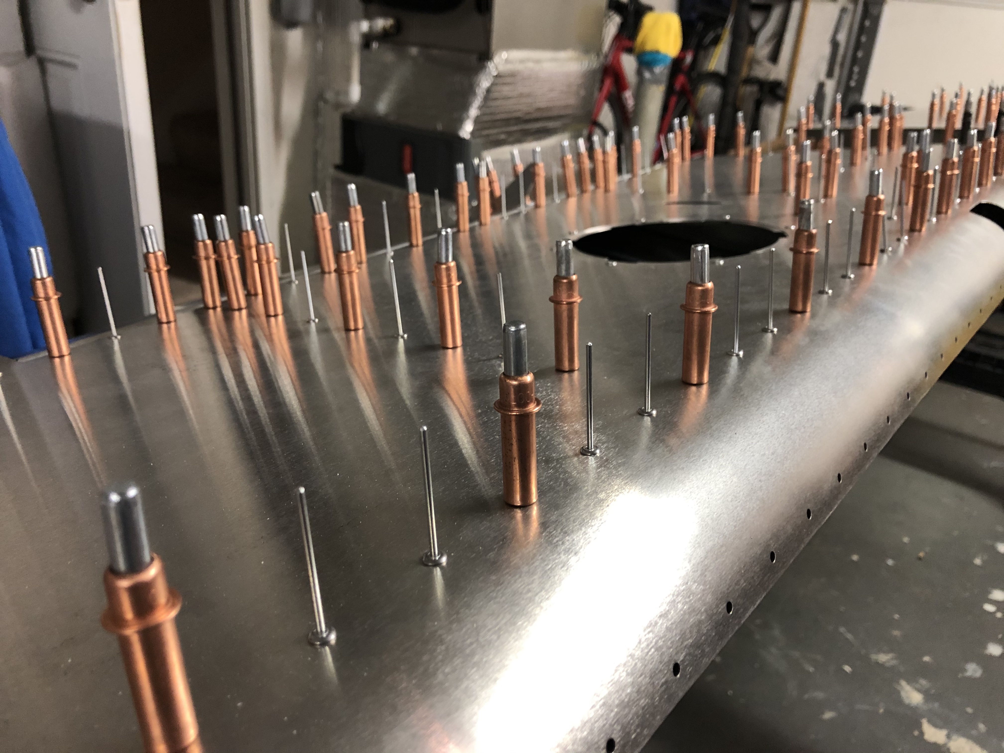
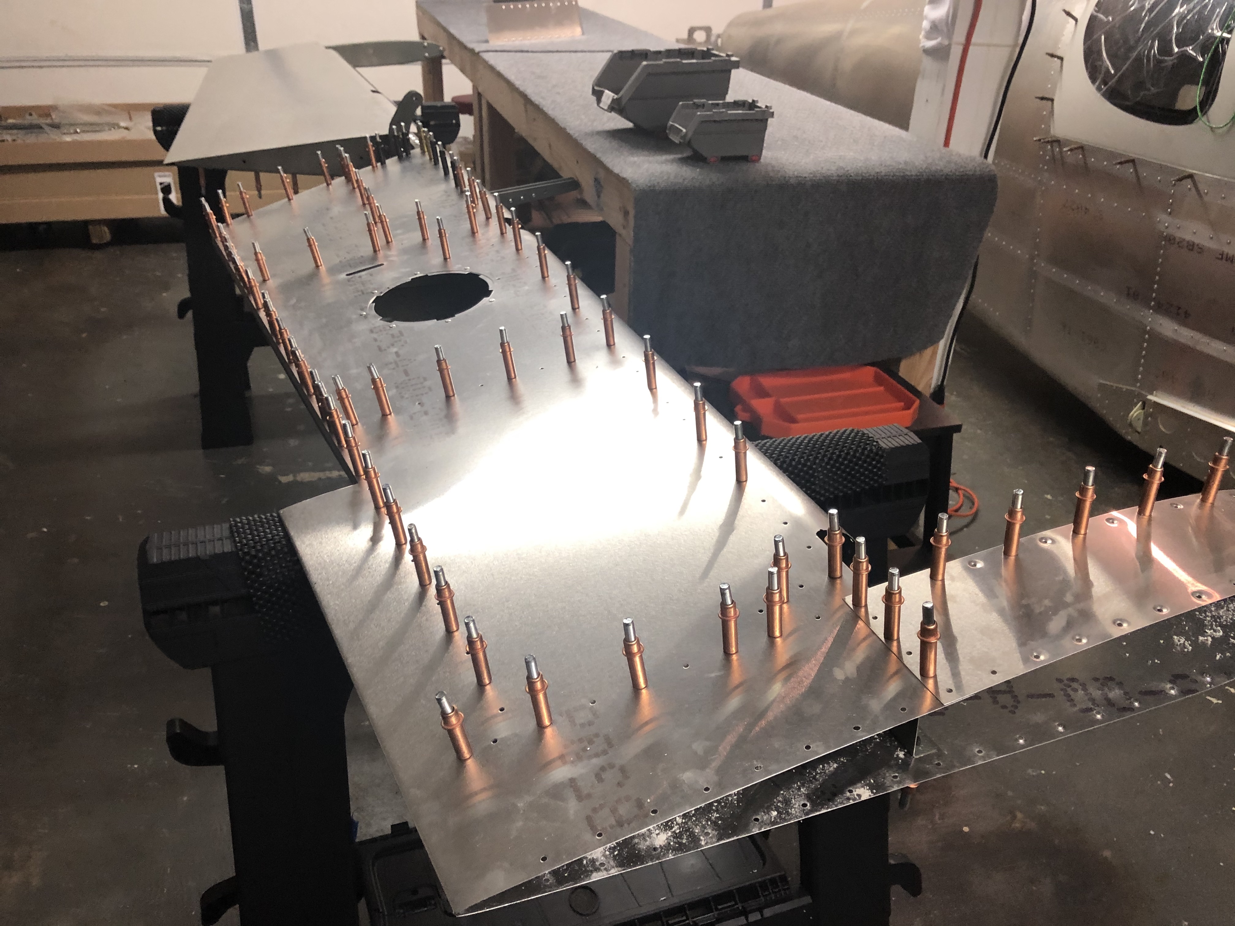
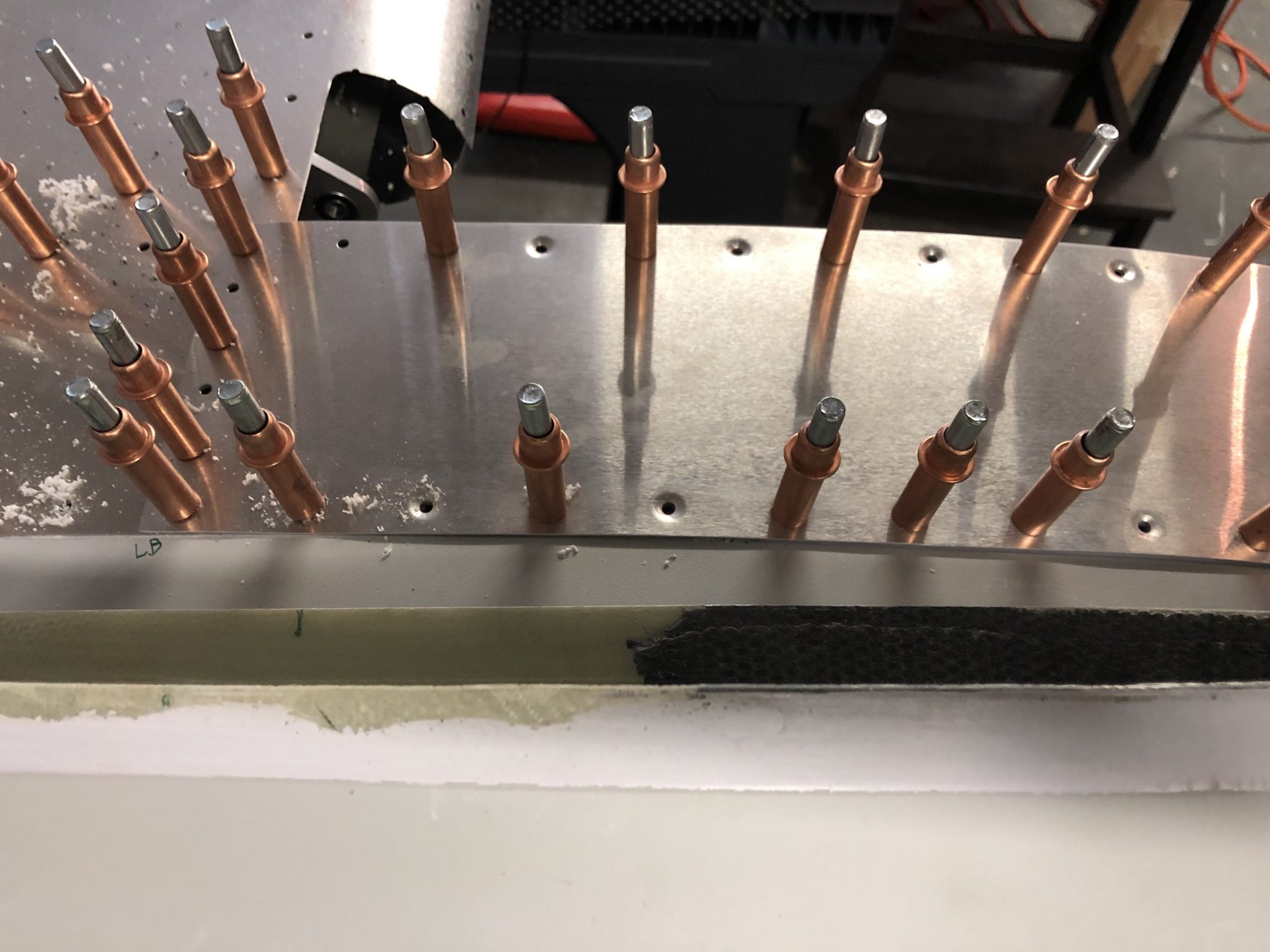
The process is pretty straightforward, but there are a lot of rivets to be pulled, so it’s a lot of repetition, so I spread the work out over a few sessions.
I first did the half of the bottom, both left and right side, and then finished up the left side completely, followed by the right side.
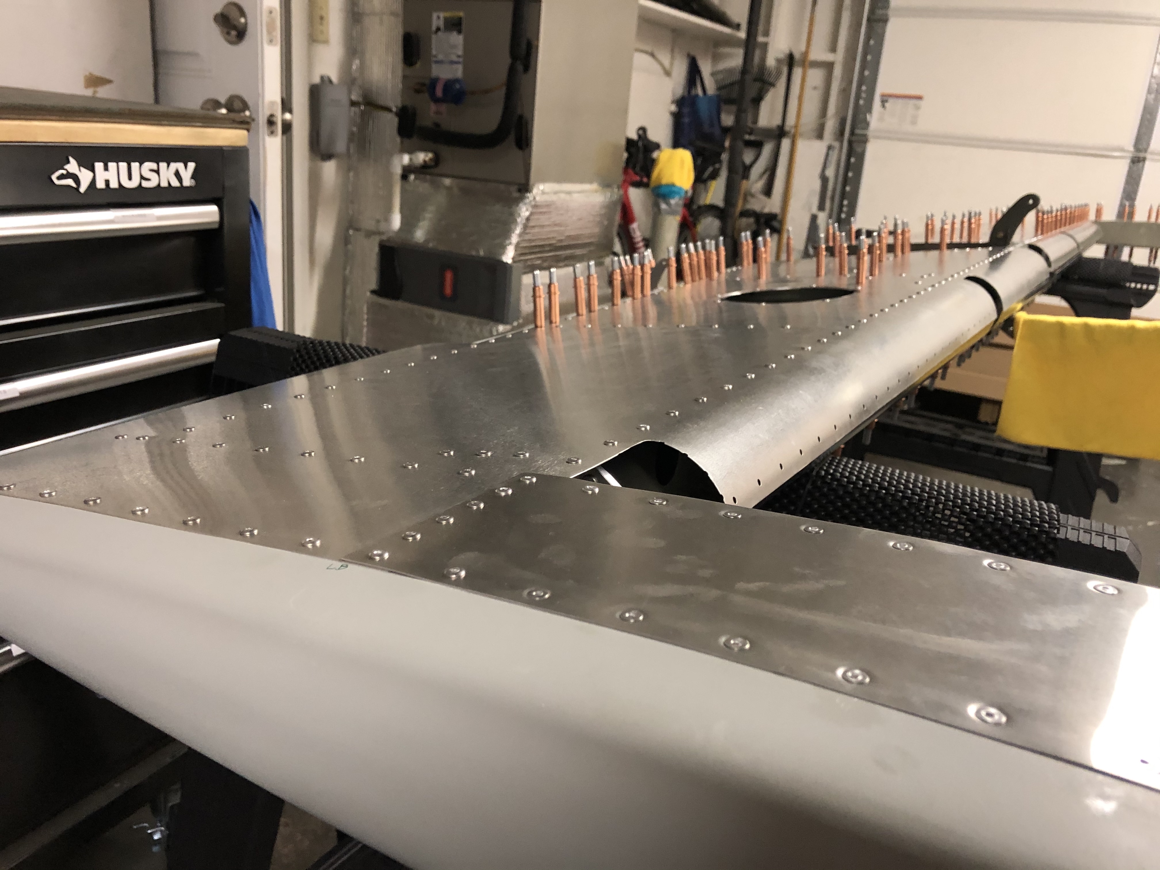
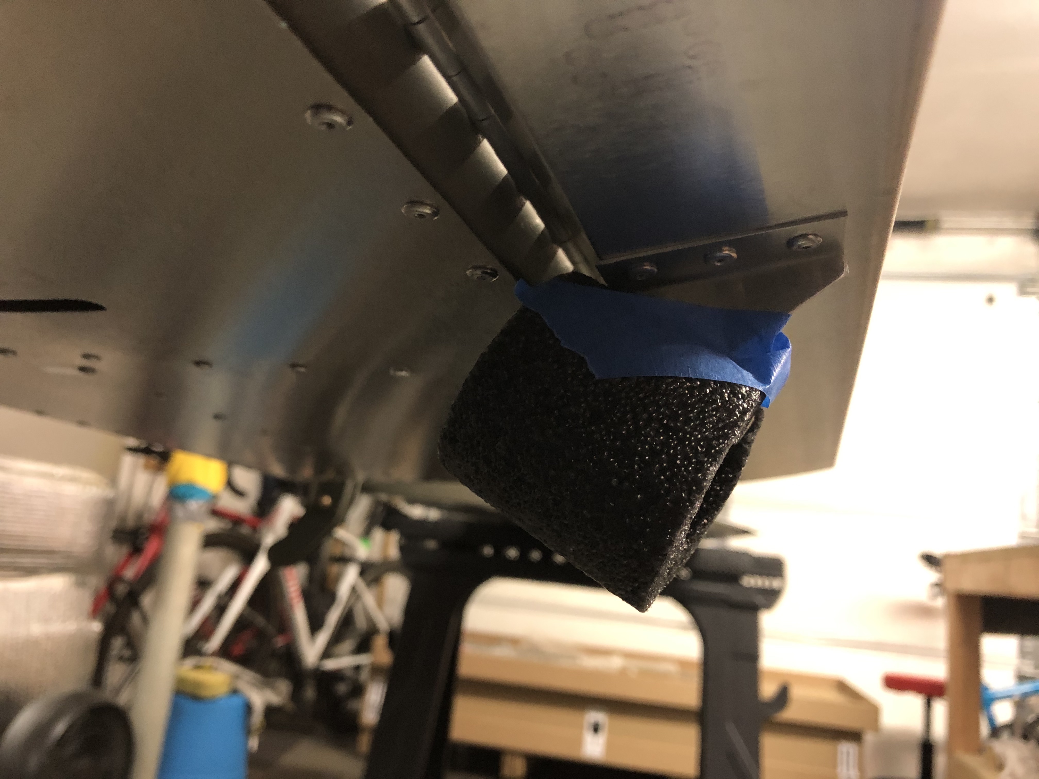
After I finished the entire bottom half of the Elevator I flipped it around and put a small padding onto the Trim Tab control so it can’t dig into the Elevator skin.
When I finished the alignment of the left side of the Elevator, I ran out of clecos, so I bought a couple more when I was at Oshkosh so I could properly put the Elevator together and get everything to align correctly.
So the first order of business was to finish clecoing everything including the (correct) control tabs for the Trim Tab.
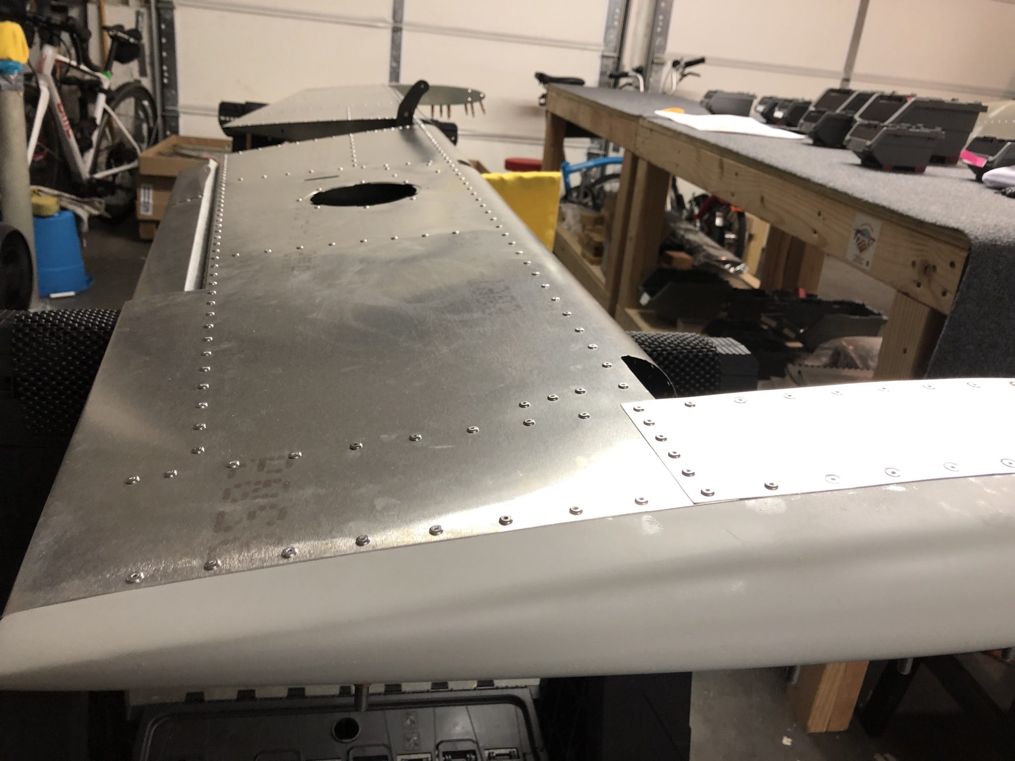
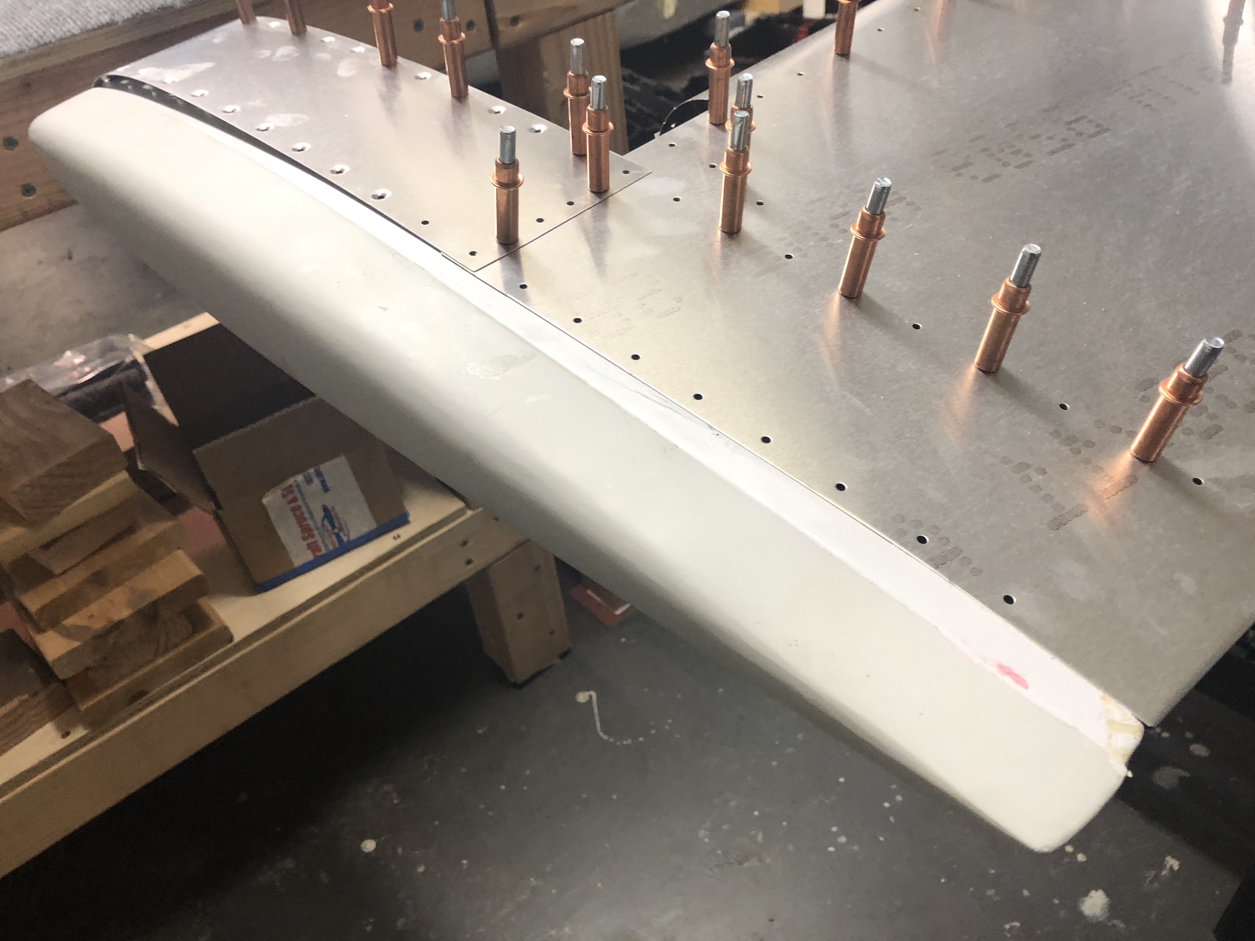
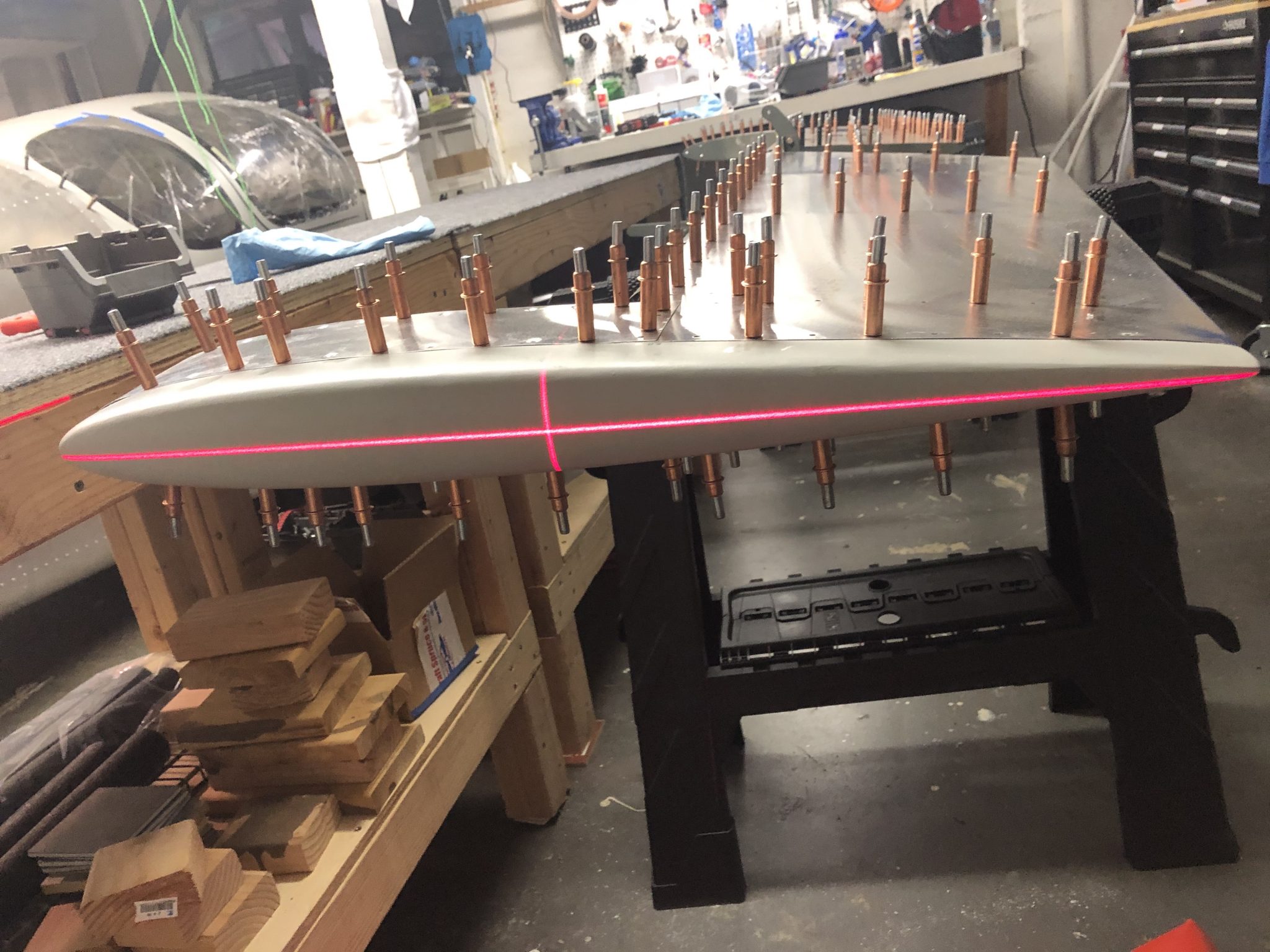
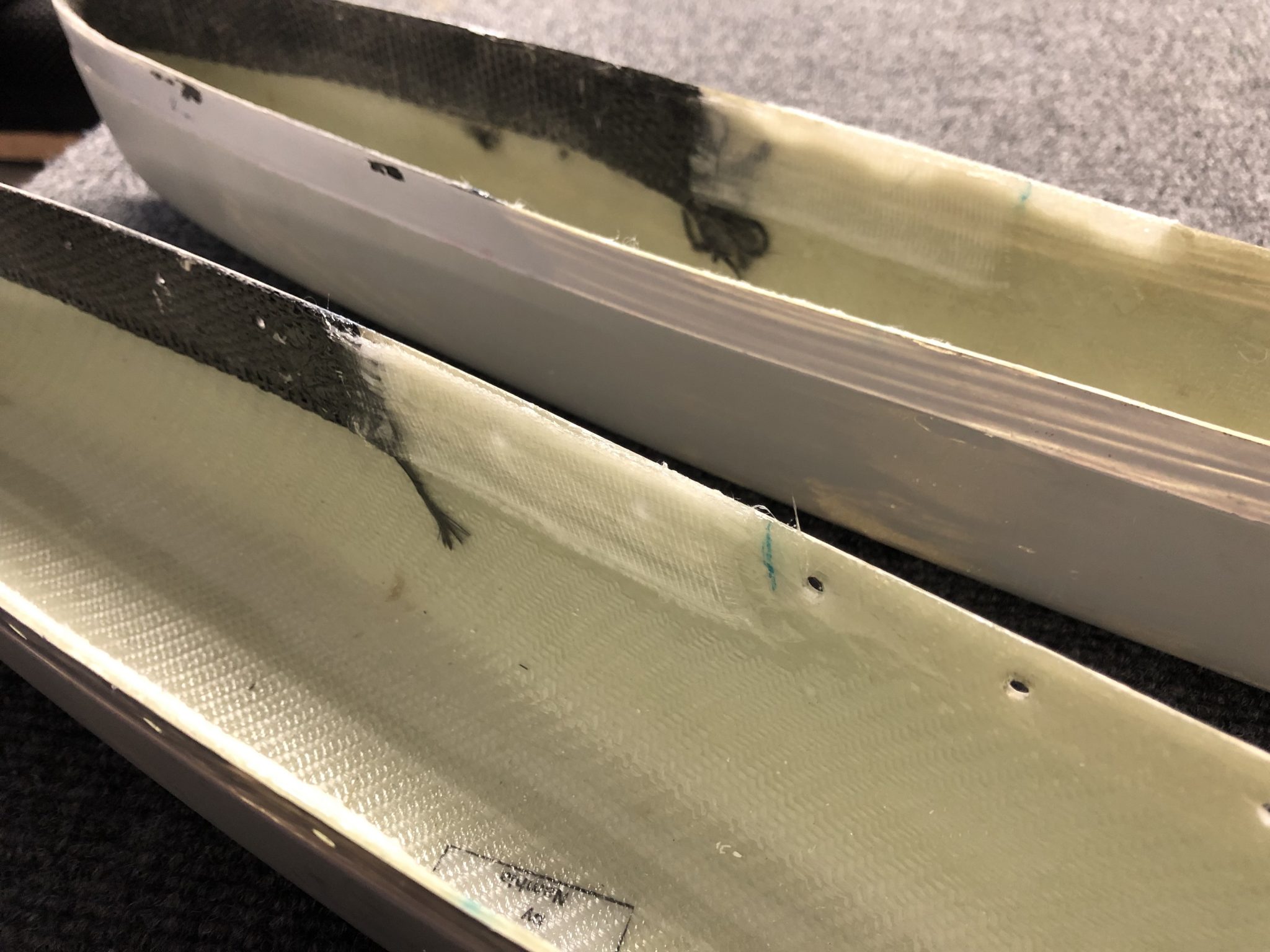
With that out of the way, I moved on to do the fitting for the right side fiberglass piece. It took a little bit of aligning and filing away a tiny bit from the back so that the fiberglass piece can slot into the metal.
Once that looked all good, I started to do the match drilling of the holed into the fiberglass.
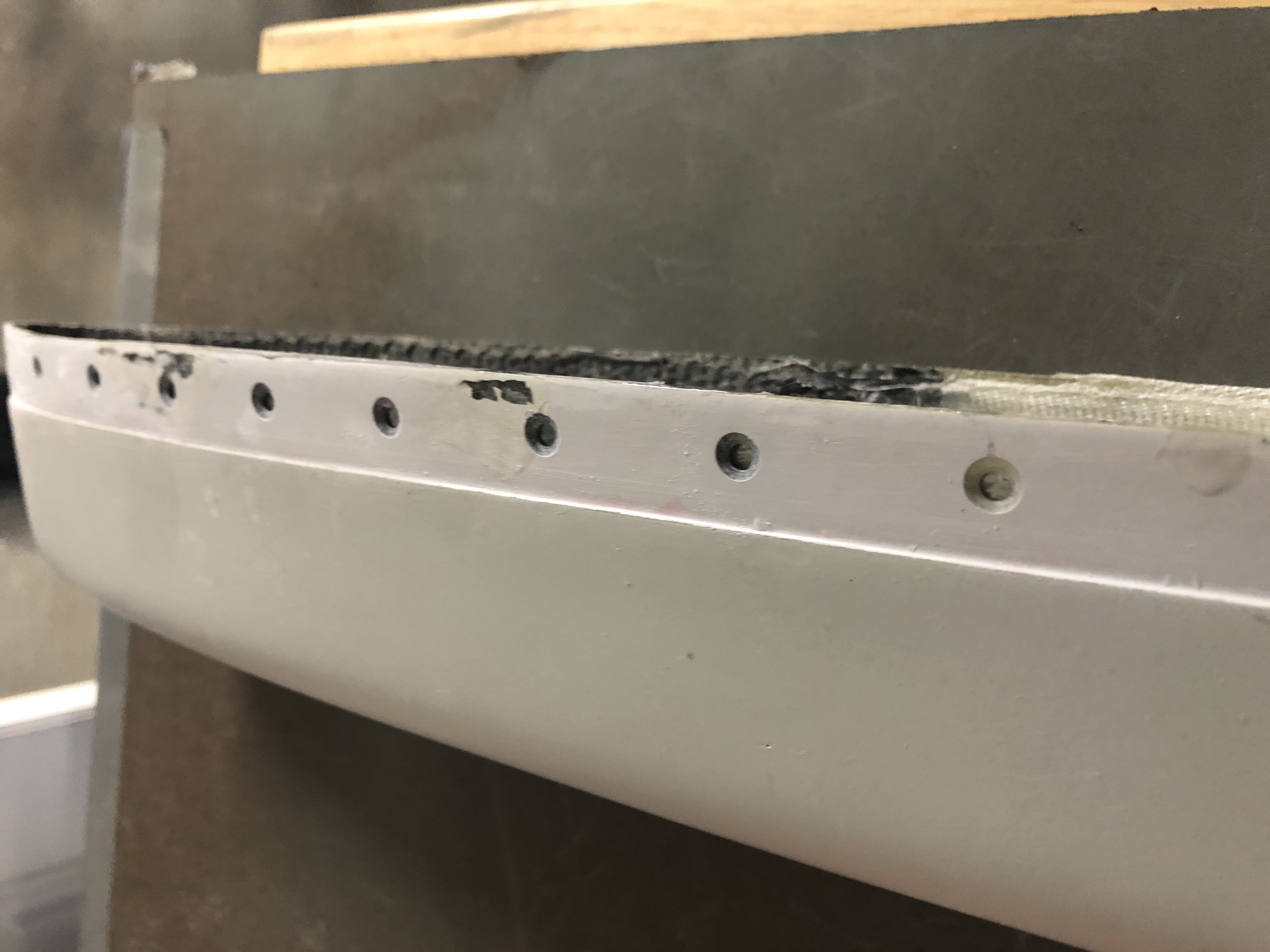
Now the only last part to do was to countersink the front parts of the fiberglass tips in order to allow the flush rivets to sit in there. It took a bit of back and forth to calibrate my microstop countersink attachments to ensure I had a good flush fitting.
The two day workshop helped in explaining principles of airplane electrical systems, wiring and bringing everything together to design and build out your avionics.
Aside from a lot of good learnings and explanations, there was also a couple of hands-on exercises to get familiar with crimping, soldering and connecting things.
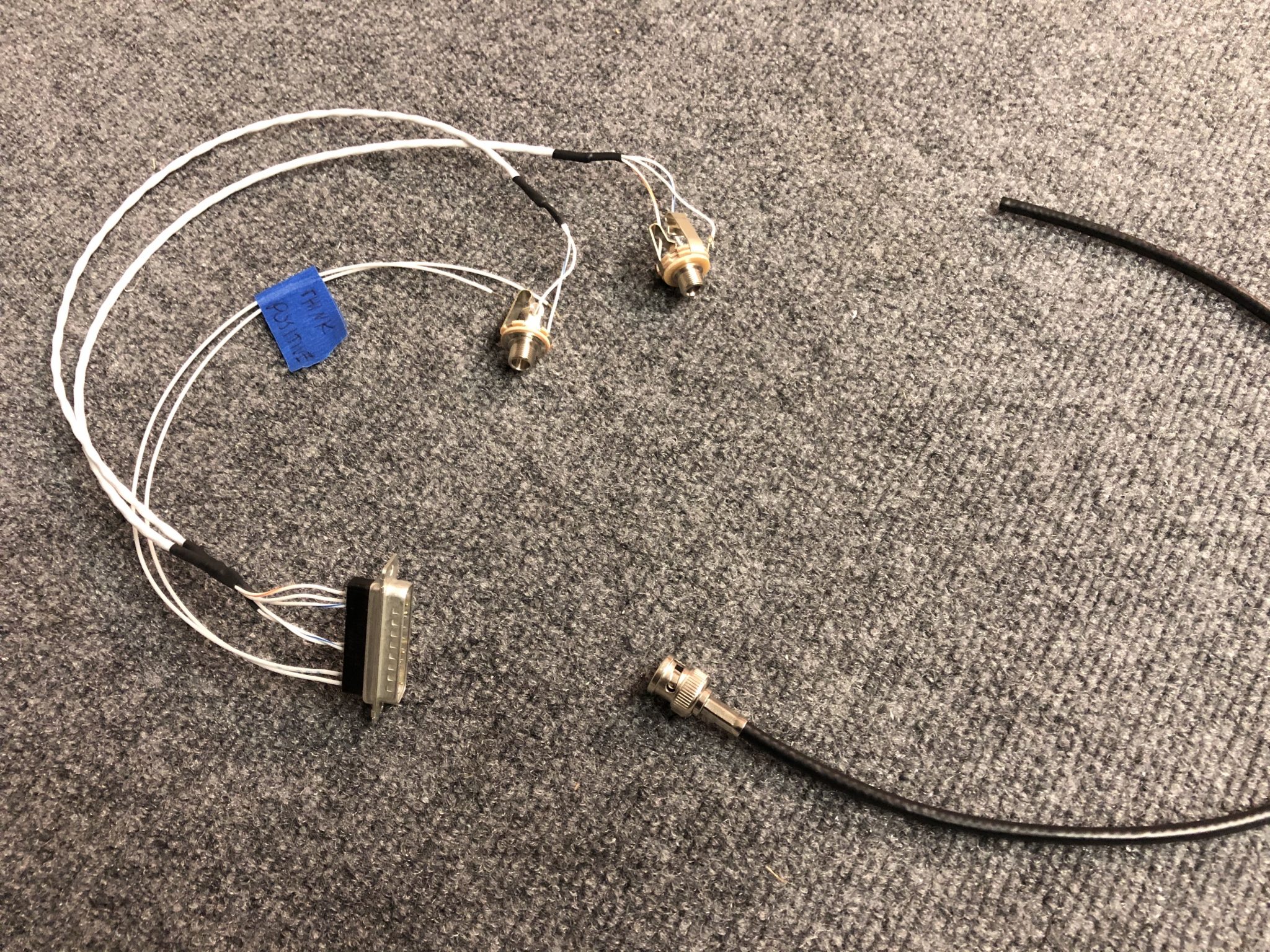
The first exercise was to hook up a headset jack to a PM1000 intercom system. This was very handy, since whether you decide to build all your avionics or not, you will most definitely have to do the headset connectors.
I forgot to take pictures of the process, but here’s the finished headset jacks with the soldered connection. This included learning to ground the shielded wire, soldering the actual headset jack and doing some d-sub crimping for the intercom connector.
Also shown in the image above is the result of the second exercise, a crimped BNC antenna connector. This part, I was already familiar with from hooking up my NAV Antenna in the Rudder a few months ago.
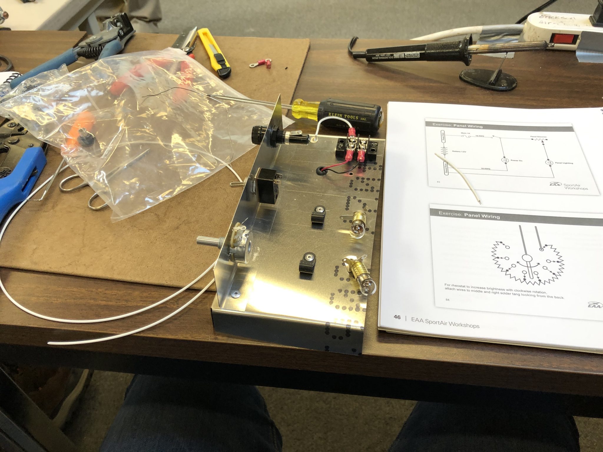
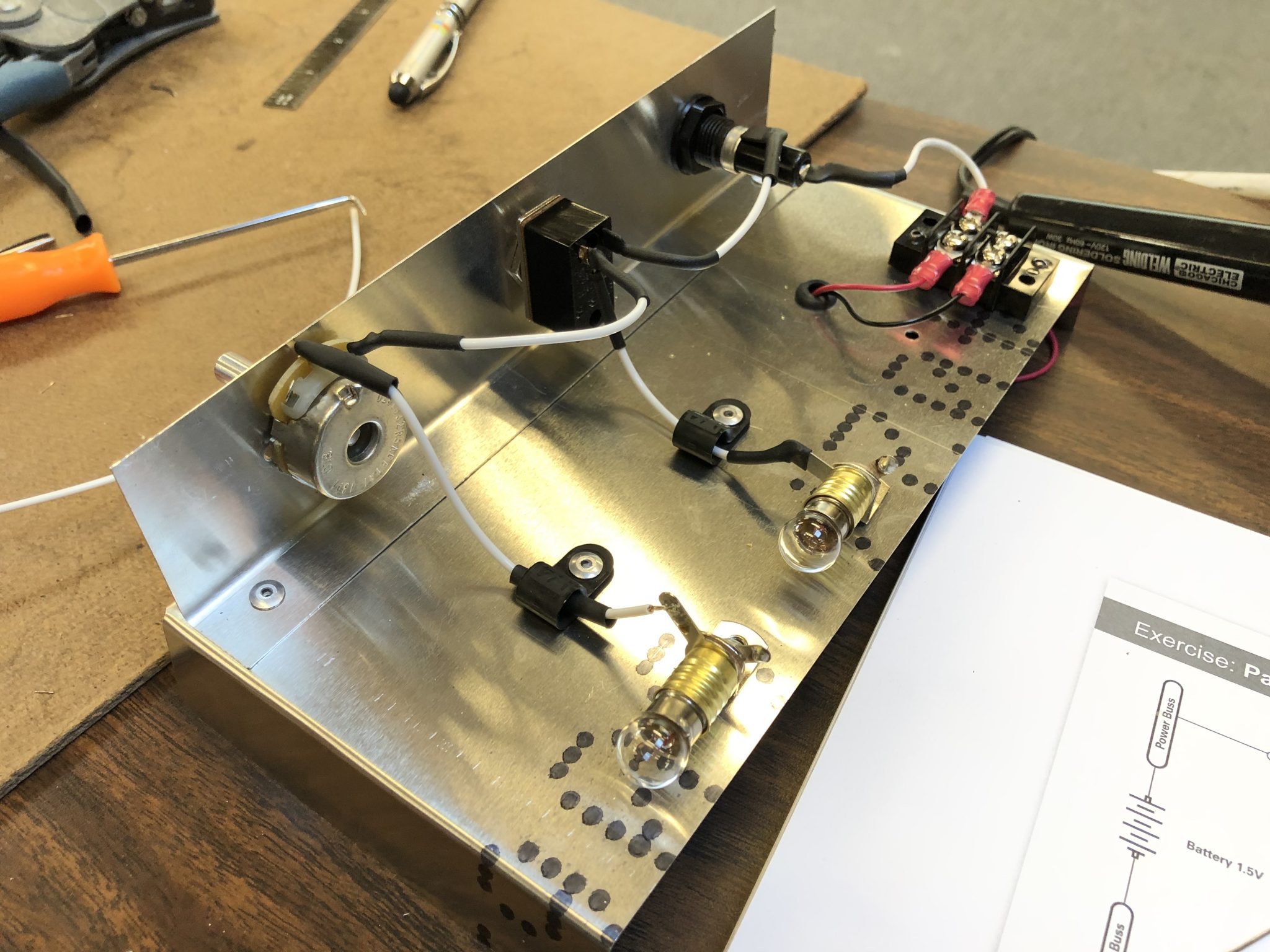
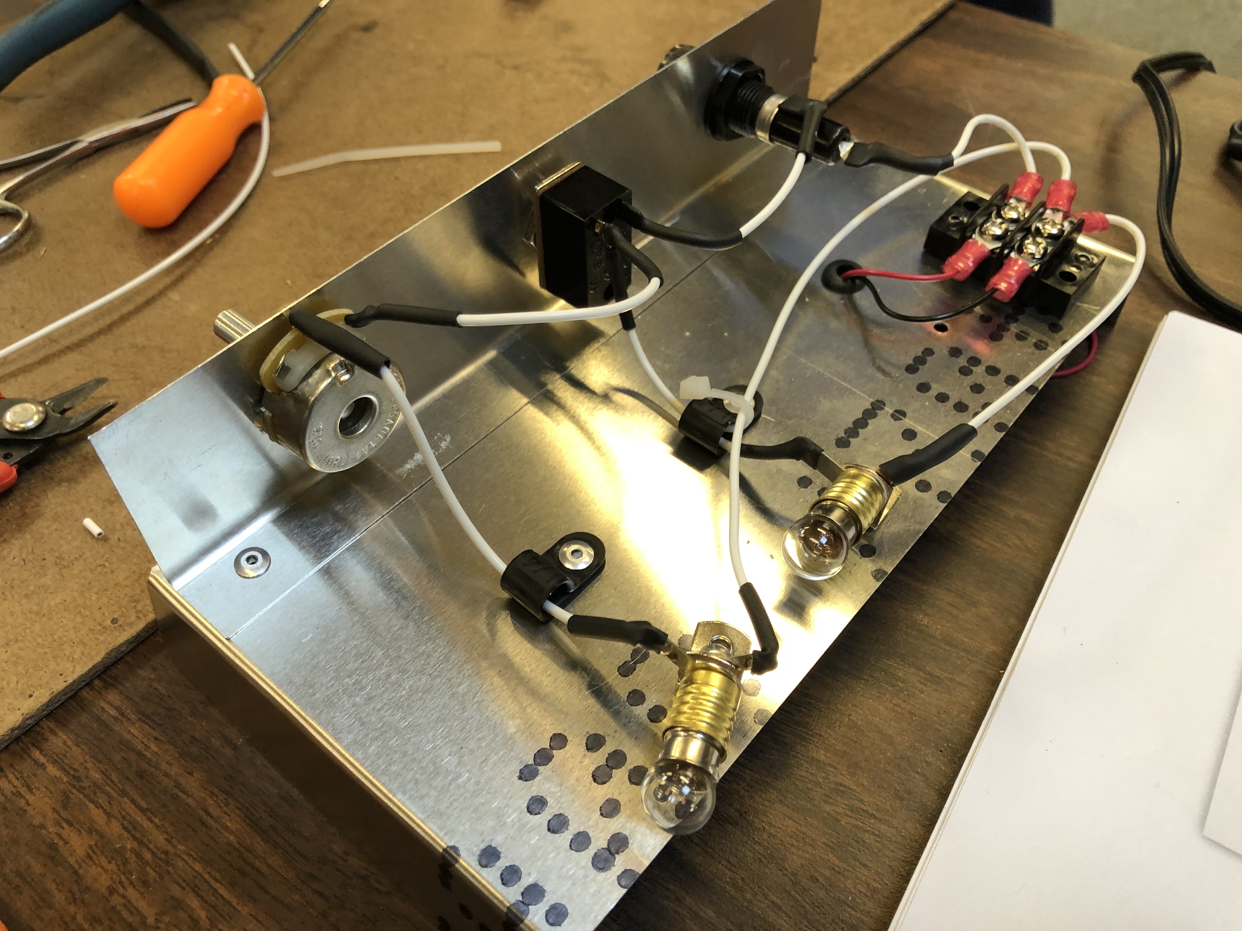
The final exercise was to create a small electrical circuit. This includes a “master” switch, circuit protection in the form of a fuse and a dimmable “cabin” light that is tied behind the master switch. Aside from the practical application of the exercise, it also tied together a lot of the theoretical parts of the workshop and was a great finish for the weekend.
Here’s the finished working circuit in action:
I also ran into two other Sling Builders, Richard Howell, who recently started building a Sling 2 and Skip Jones, who is also building a Sling TSi. Now we just need to all finish building our airplanes and then we can be a chapter of Sling Pilots in the Pacific Northwest.
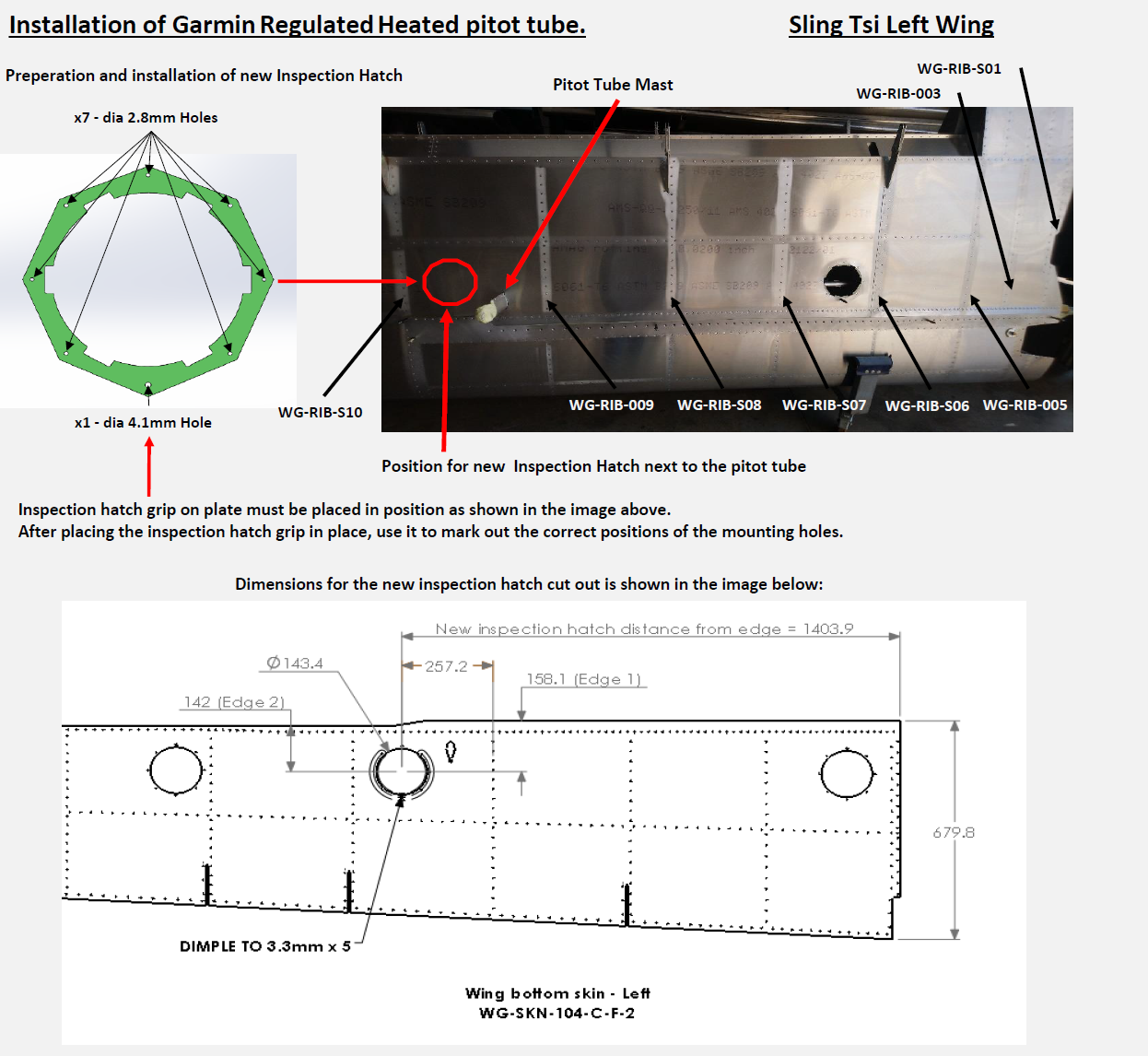
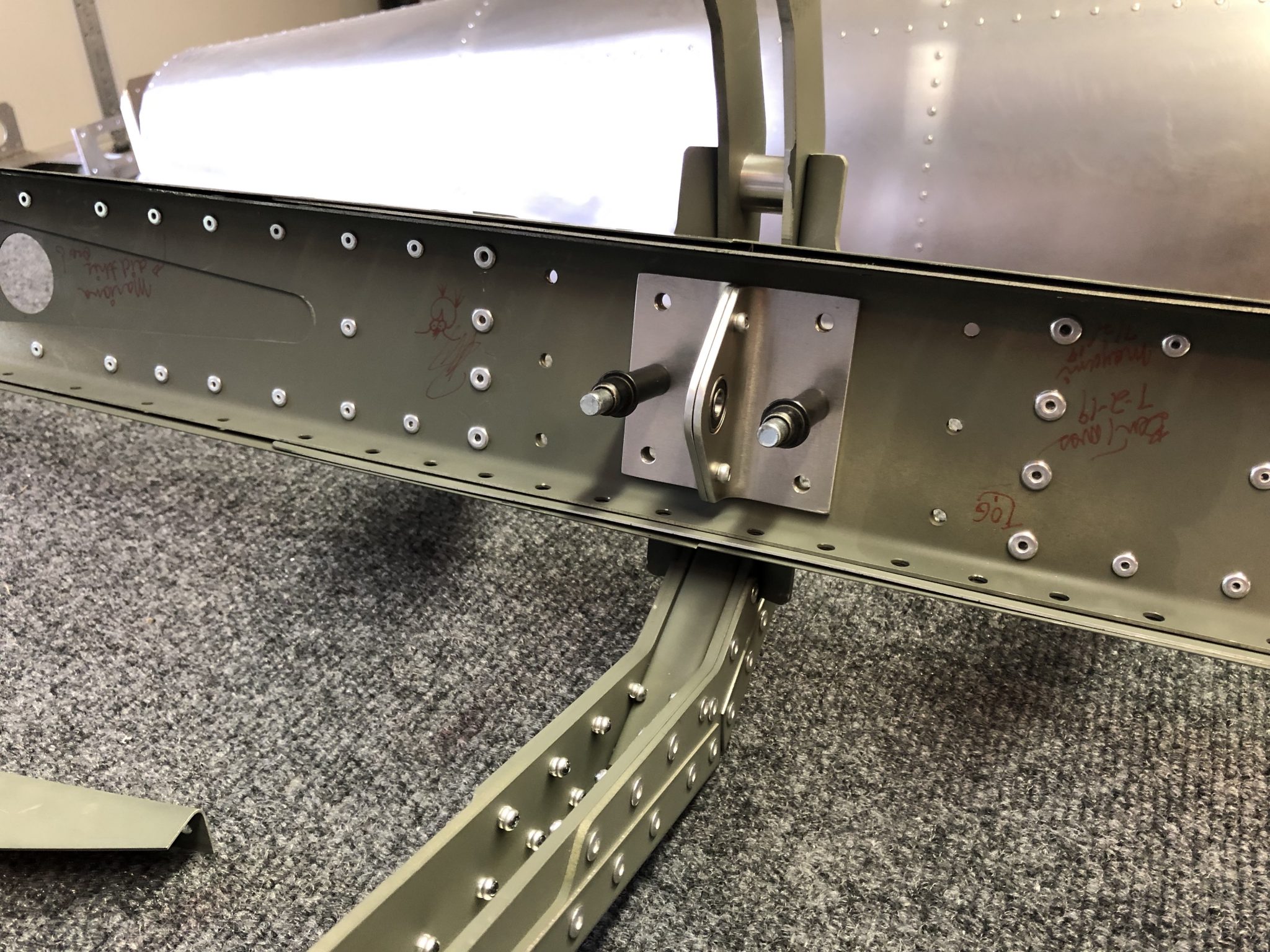
One of the things that the factory forgot as part of the change from the Sling 4 to the Sling TSi was the required access to the internals of the wing next to the Pitot tube.
In the Sling TSi design, some inspection panels were removed including the one next to the Pitot tube. By itself, if someone was building the wings from scratch, that might be fine as long as the builder installs the Pitot tube beforehand and doesn’t anticipate to ever need to access it, such as if using an unheated Pitot tube.
However, I am going to use the Garmin heated & regulated Pitot tube, which not only requires wires to be run to the Pitot tube, but also that I need to mount the regulator unit next to it.
Since I ordered the quickbuild, I ordered it with this specification, but unfortunately the factory didn’t receive the Pitot tube from their supplier in time and shipped my kit without installing it.
So after I received my shipment and inspected everything, I realized that installing this after the fact wasn’t going to be easy, particularly with the lack of a hole in the wing. Unfortunately the factory also forgot to run the wiring to the pitot tube, which creates a whole second issue, for which I’ve been working on a solution.
I informed the factory a while ago and also gave Matthew, one of the other TSi builders a heads-up since he hadn’t started on the wings yet. The factory realized their mistake in the plans and promised to come up with a solution and send me instructions and a plan.
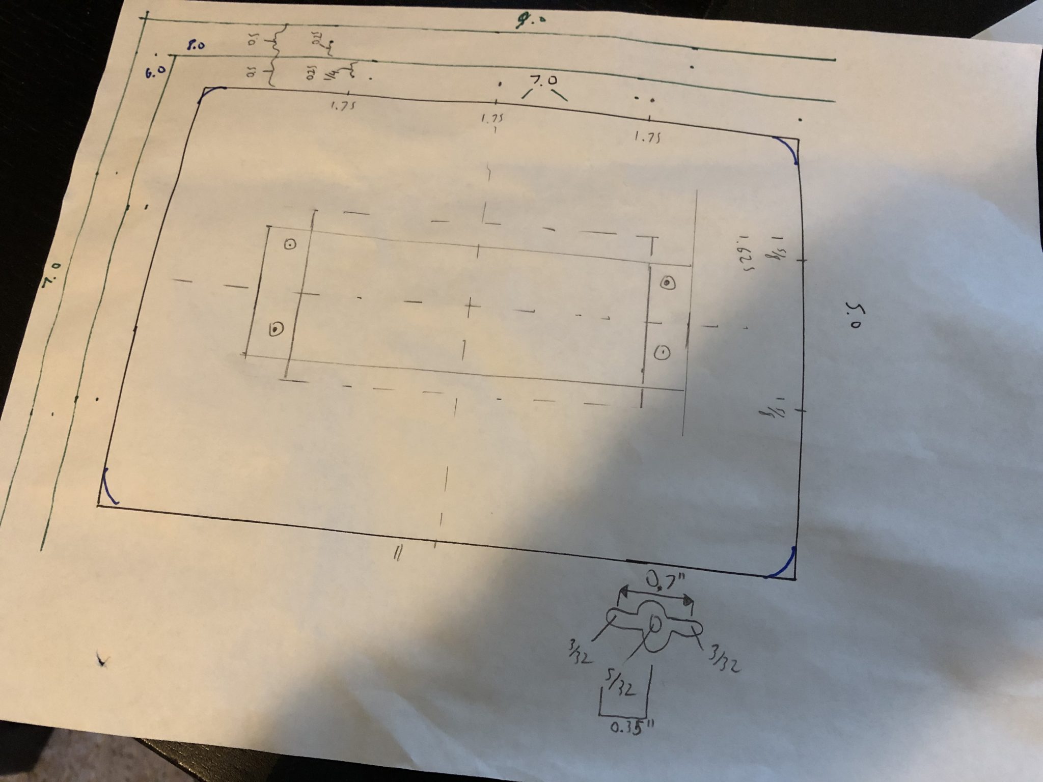
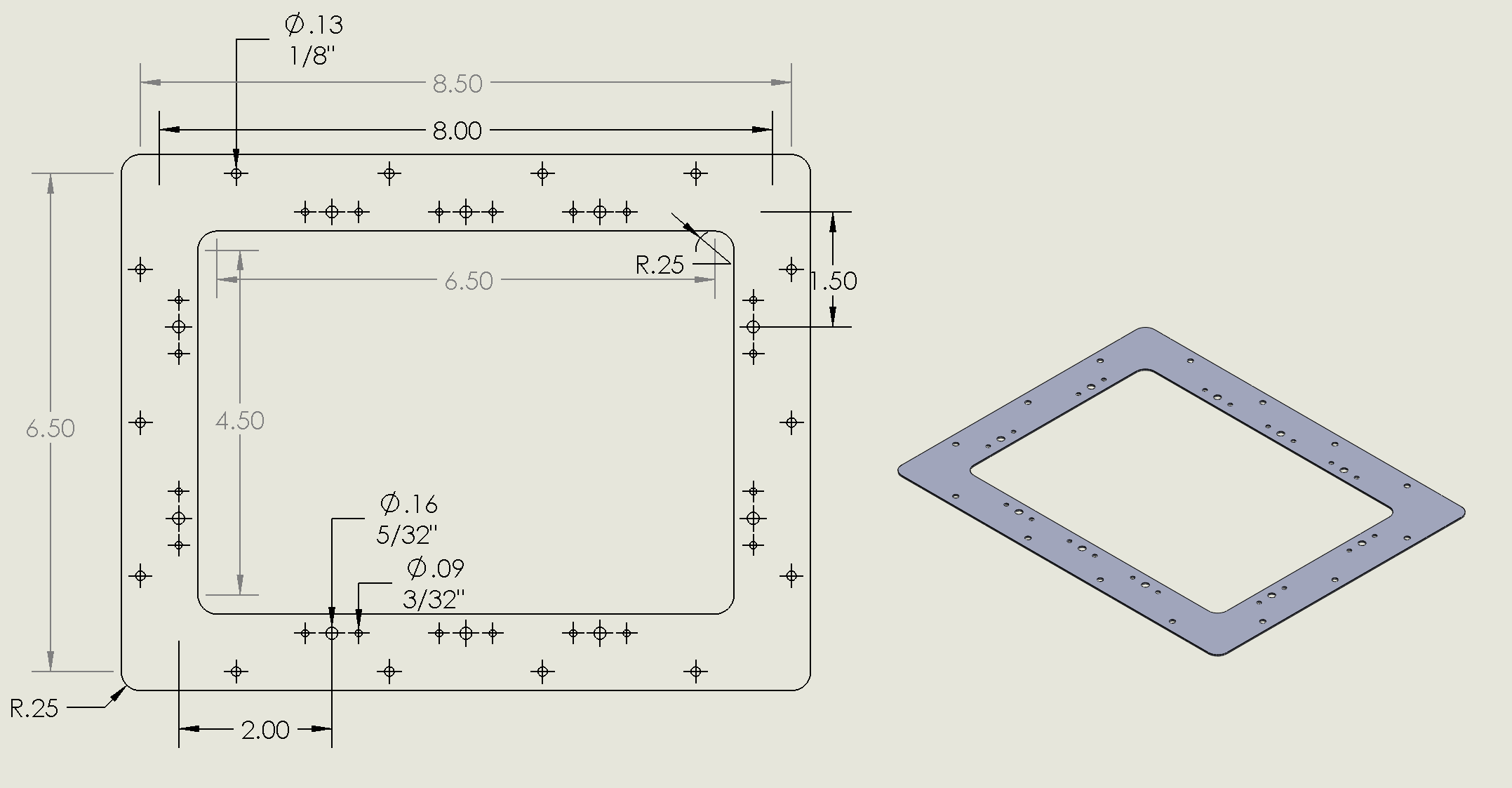
Drafting a plan
While I was waiting for the factory to come up with a plan, I actually started drawing up my own plans to fabricate the entire inspection panel myself and used it as an opportunity to learn and use Solidworks, which I can use for free as part of being an EAA member.
Since I had the chance to chat with Mike Blyth at Oshkosh for a while and we chatted about my build, I mentioned that I was still waiting for the factory to come up with a plan for the inspection cover and he promised that he’d check on the progress when he got back to South Africa and indeed, two weeks later, I got an email with the plans.
The factory plans, in keeping with the other inspection access panels, uses the same flush round inspection cover that is used to access the Flaps and Aileron connecting rods.
Since I am still busy with other things in the build and haven’t actually made my own panel yet, I am going to go with the factory plans that they have drawn up for me.
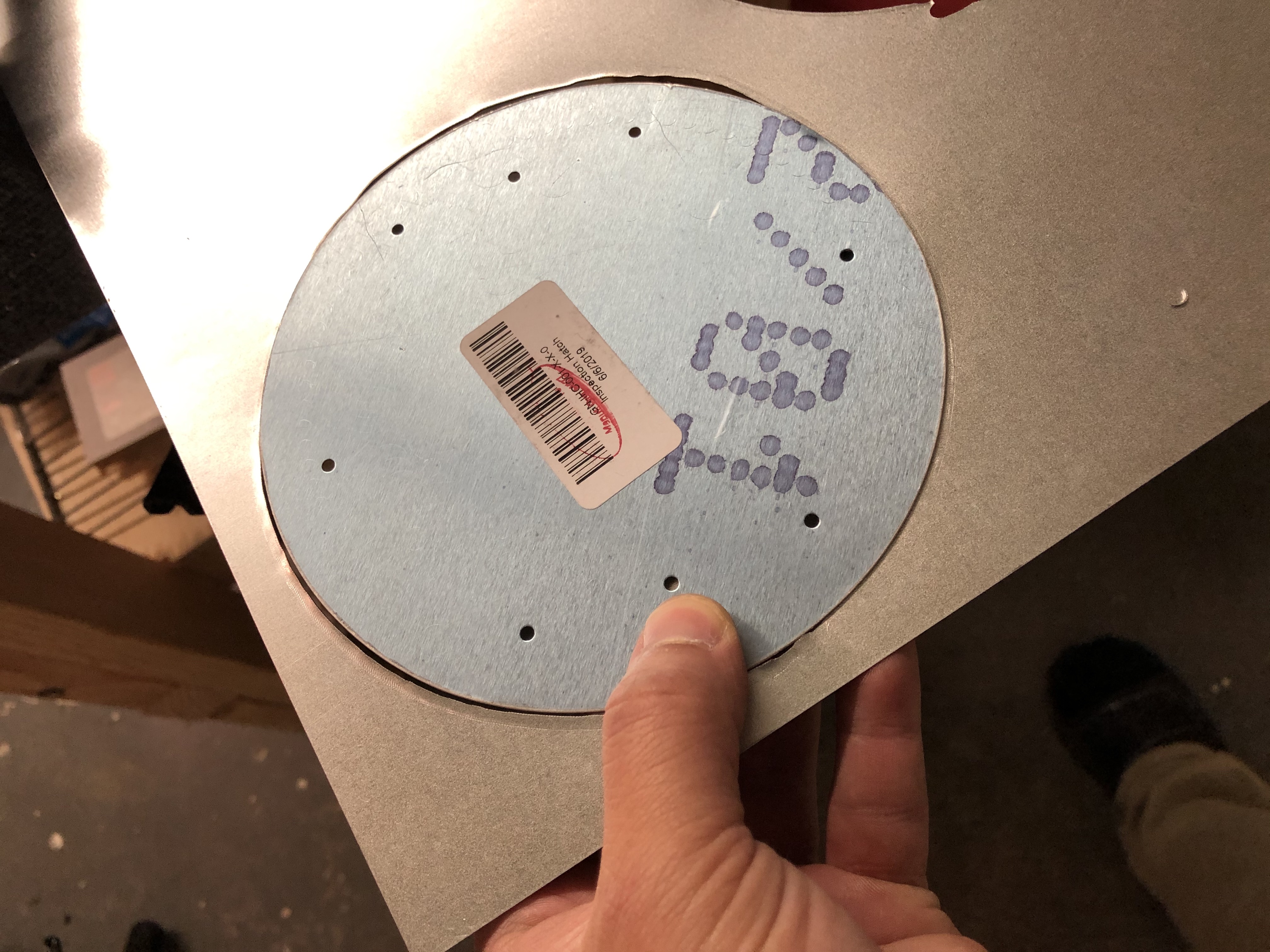
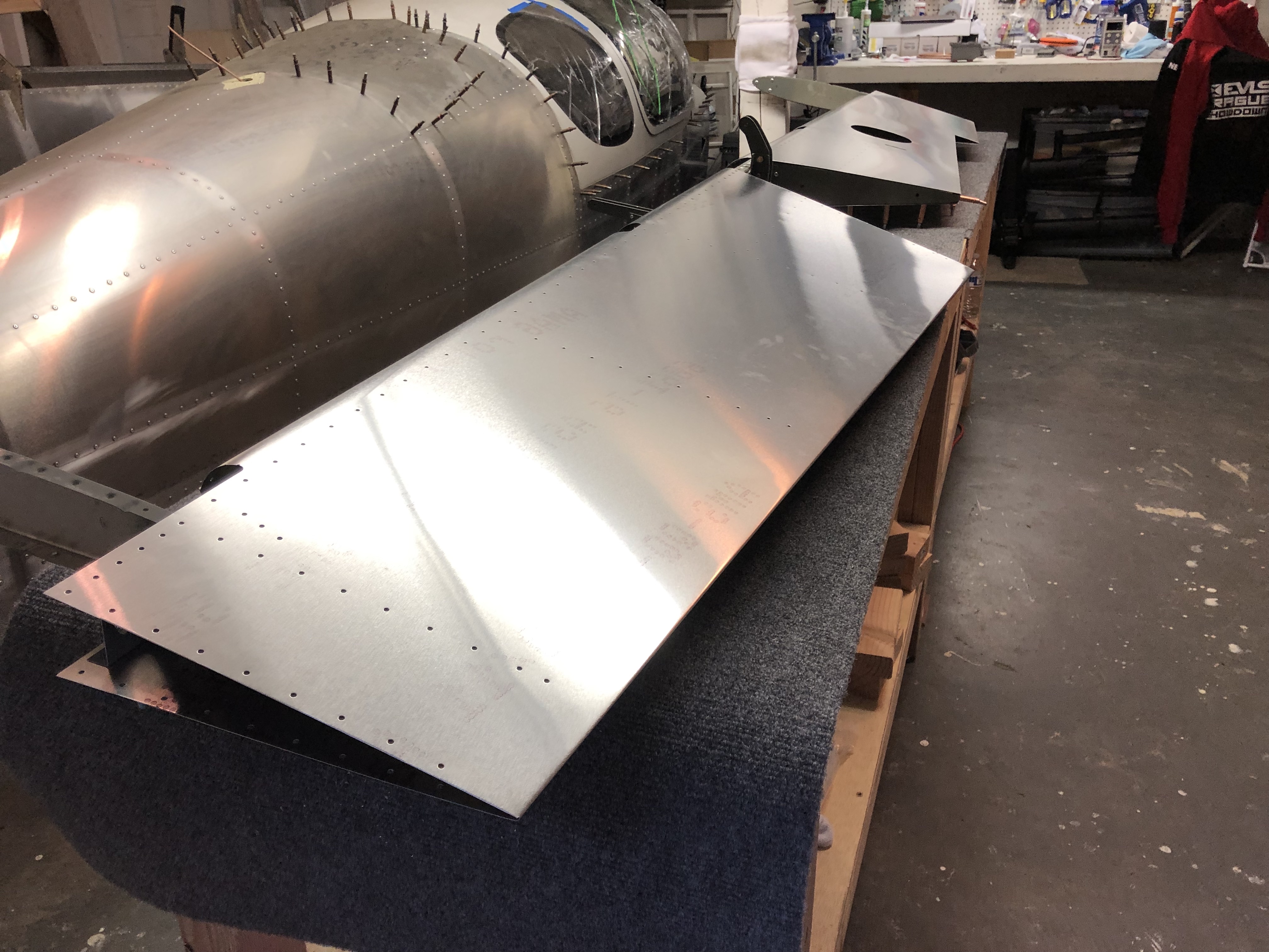
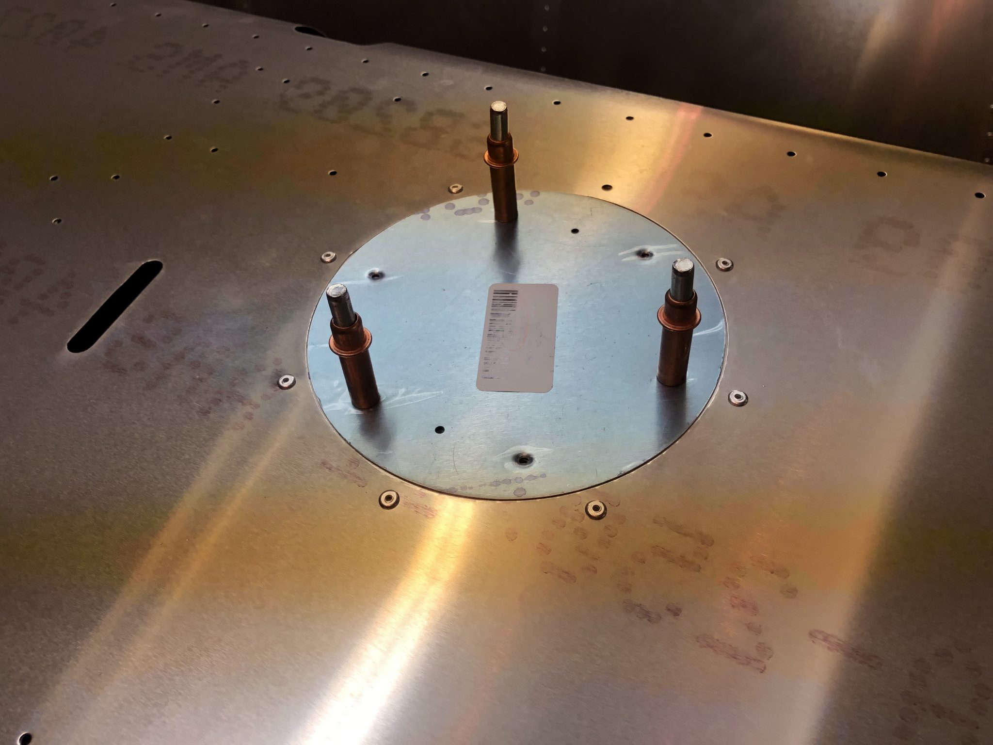
Cutting a round inspection access panel hole
There is just one difficulty to overcome – the access panel is round and large and I don’t think there are 143.4 mm drill bits I can buy in Home depot.
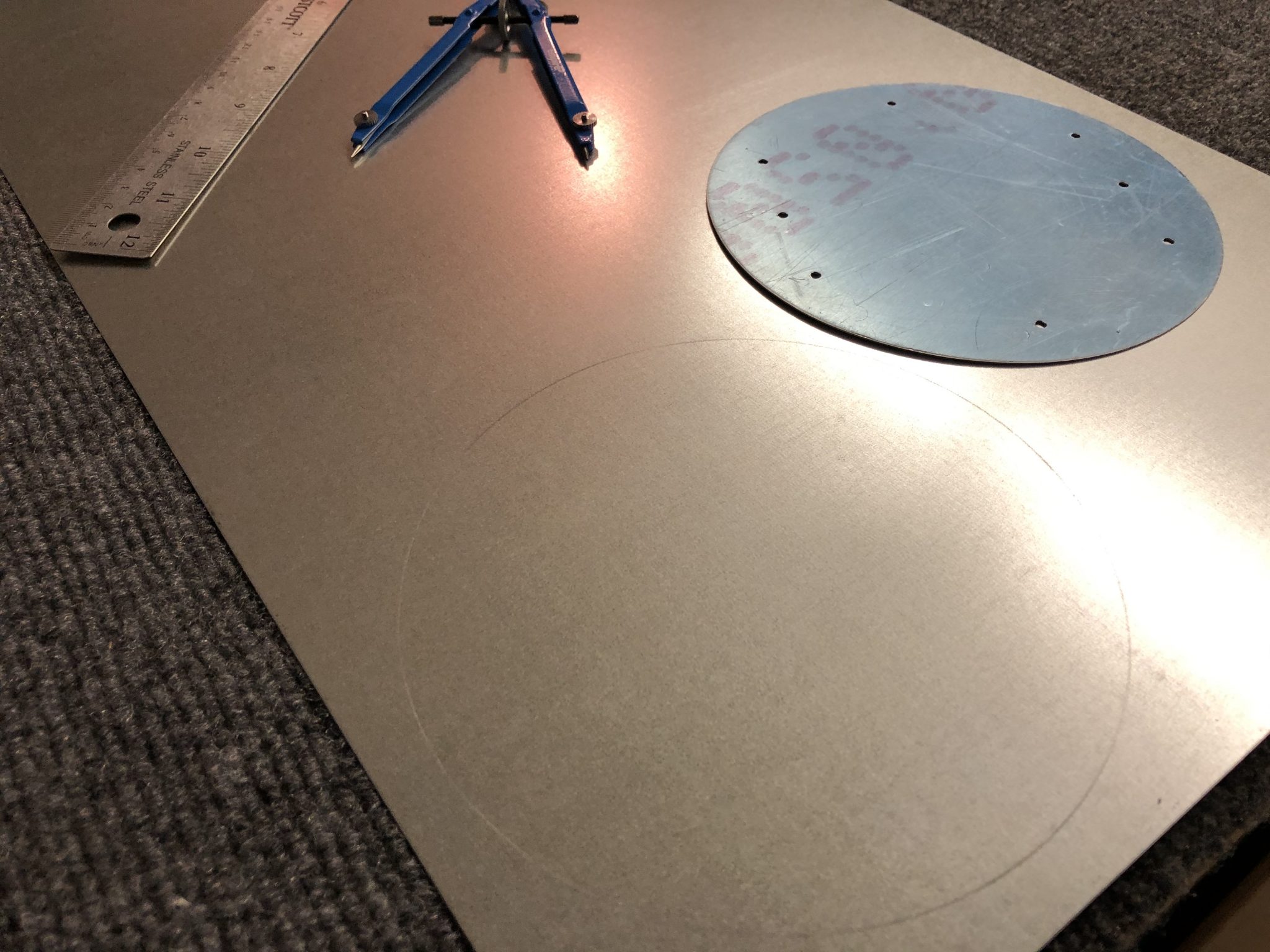
Since this is quite an operation, I decided to get some practice with the tool on a piece of spare aluminum and also made a video of it, since I figured that it might be helpful for other builders in the future.
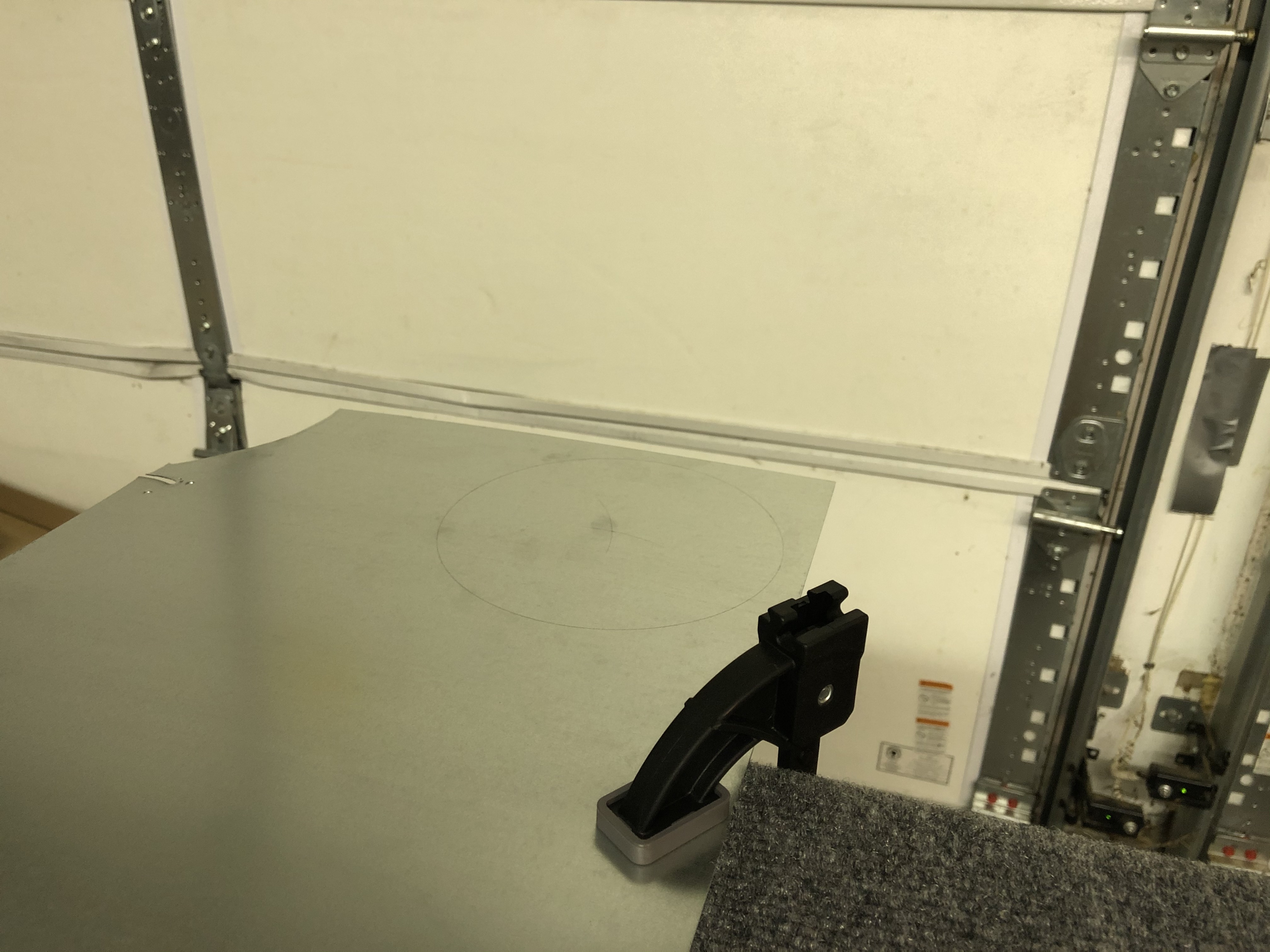
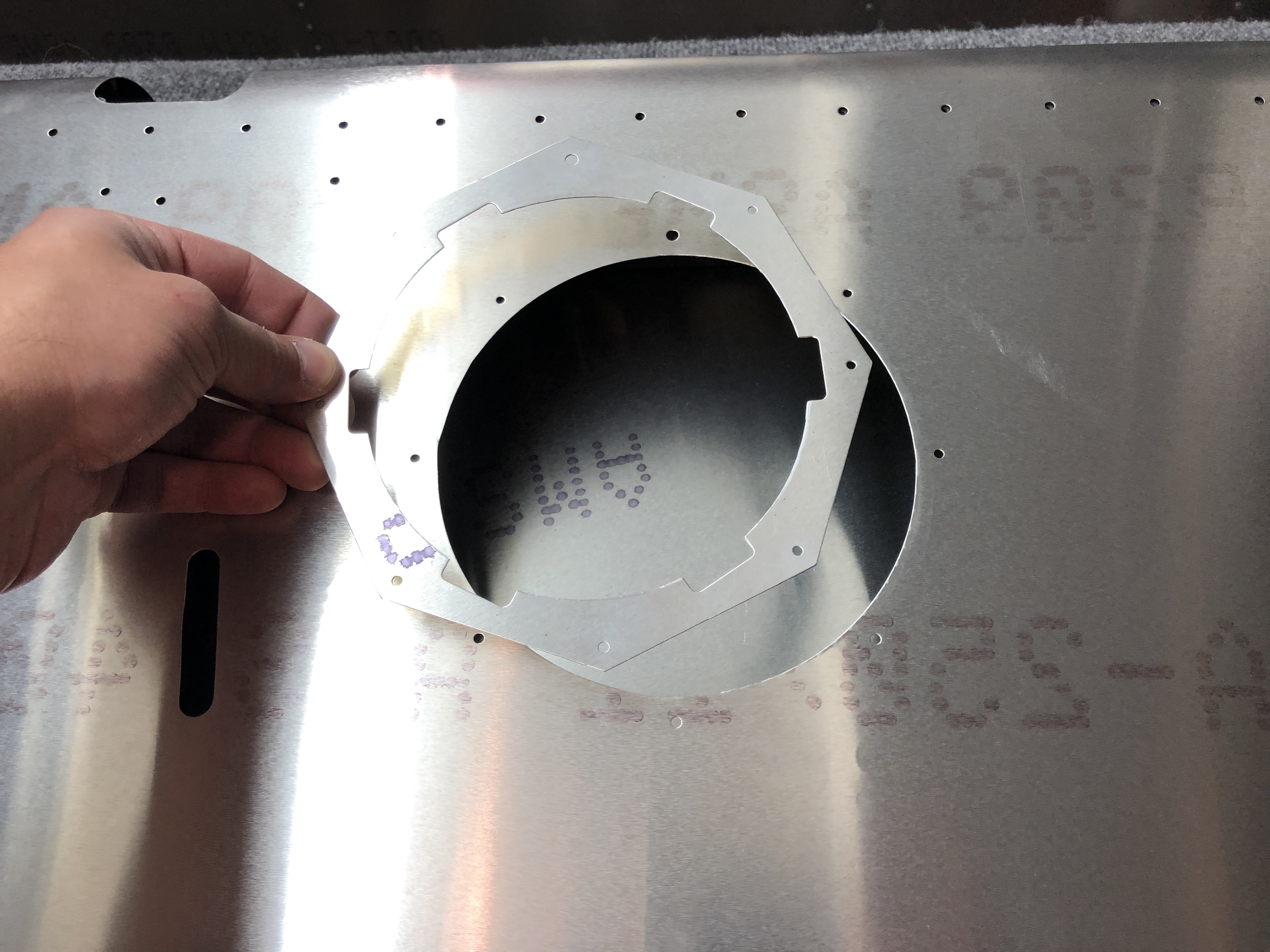
I started by marking out the circle using a drafting compass. It’s been quite a few years, but luckily I still remembered how to use it and how to find the center of the circle again by making two marks. Proof that you may indeed use what you’ve learned in geometry class sometime in life, even if it’s 15 years later. After that I clamped the piece of metal on the edge of the table.
I drilled the center pivot hole to 1/8th of an inch, which makes the pivot sit in the hole and then measured out the starting hole for the drill, make a starter hole and then used a step drill bit to upsize the hole until it aligned with my marked circle.
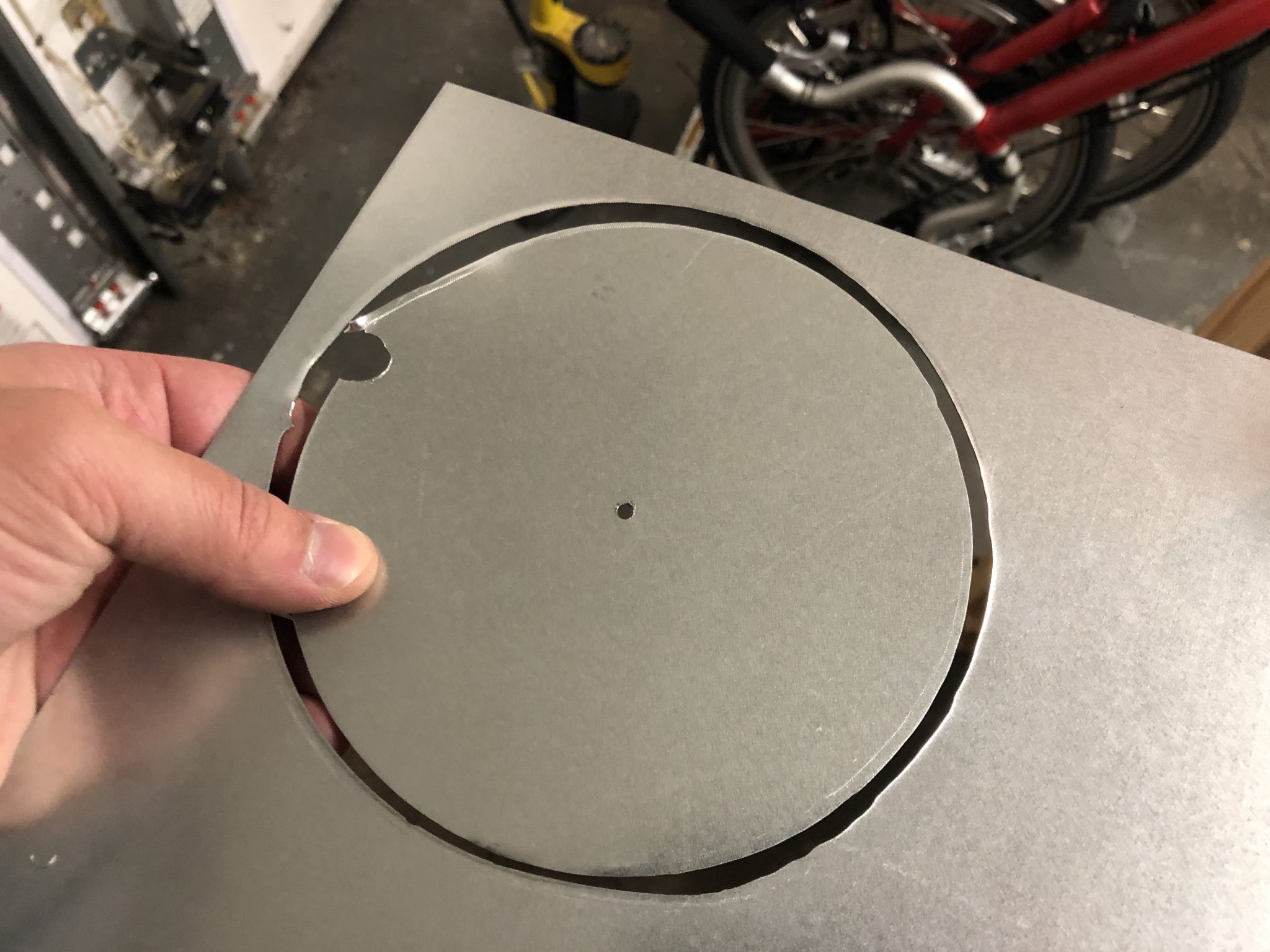
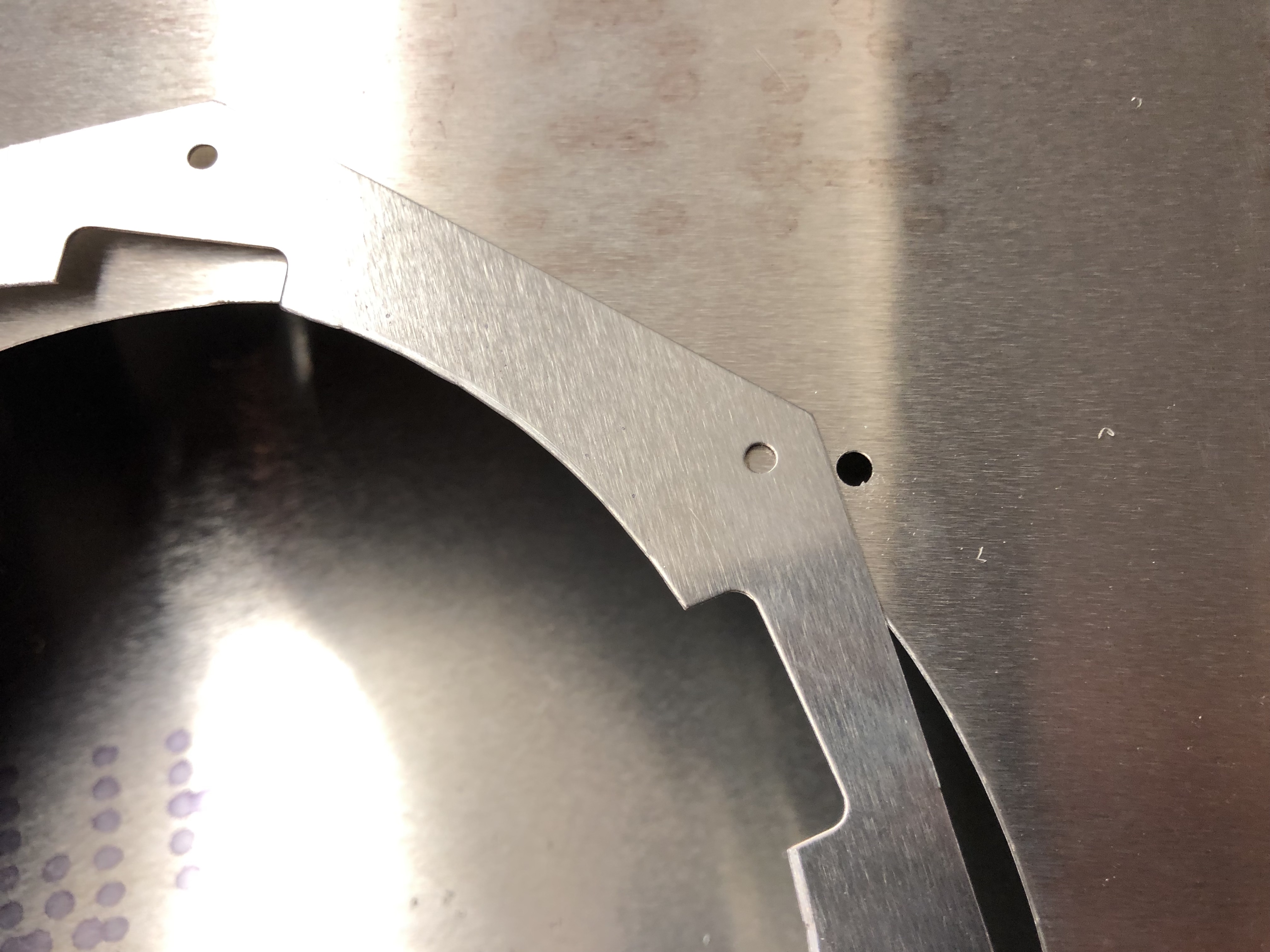
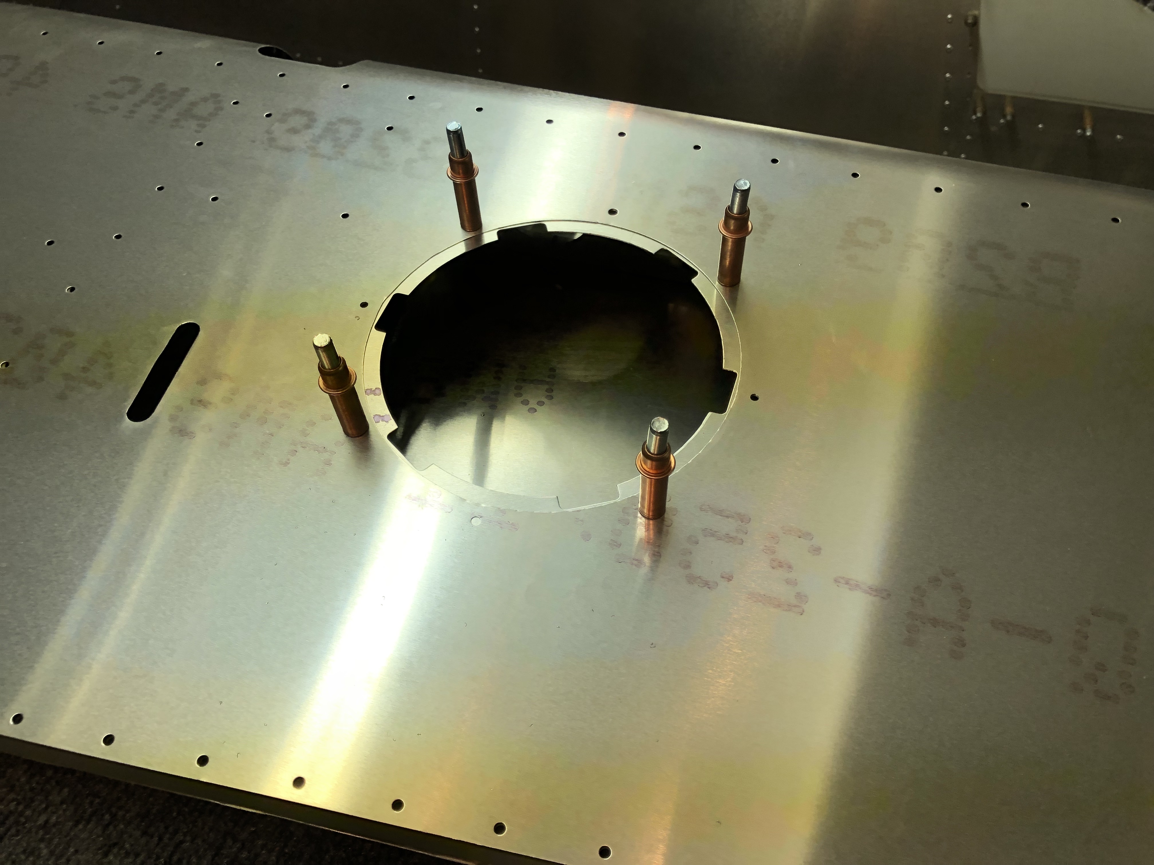
After that, I set up the drilling tool with the pivot and made sure that the outside of the cutting bit aligns with my circle and then attached the drill and went to work.
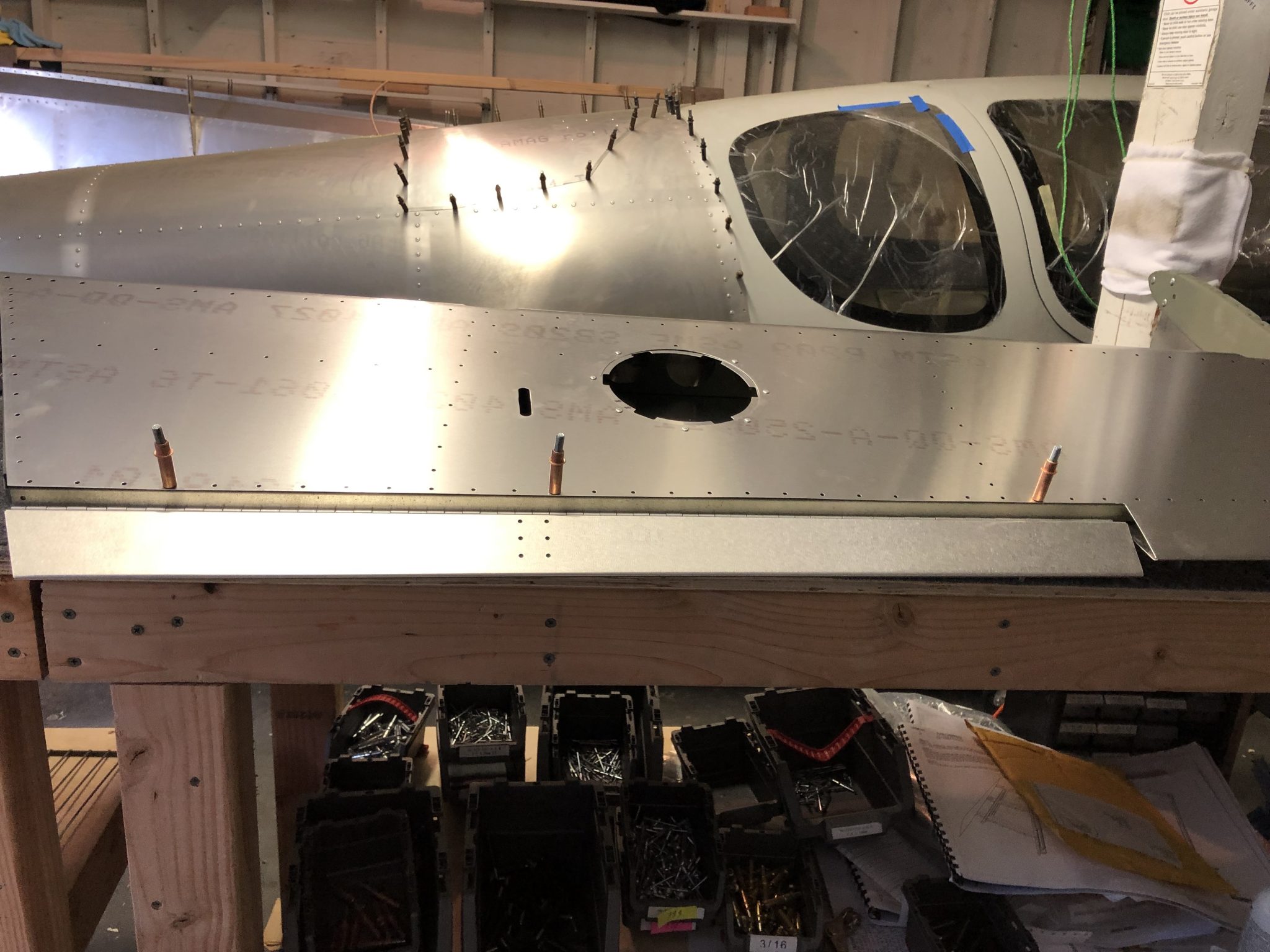
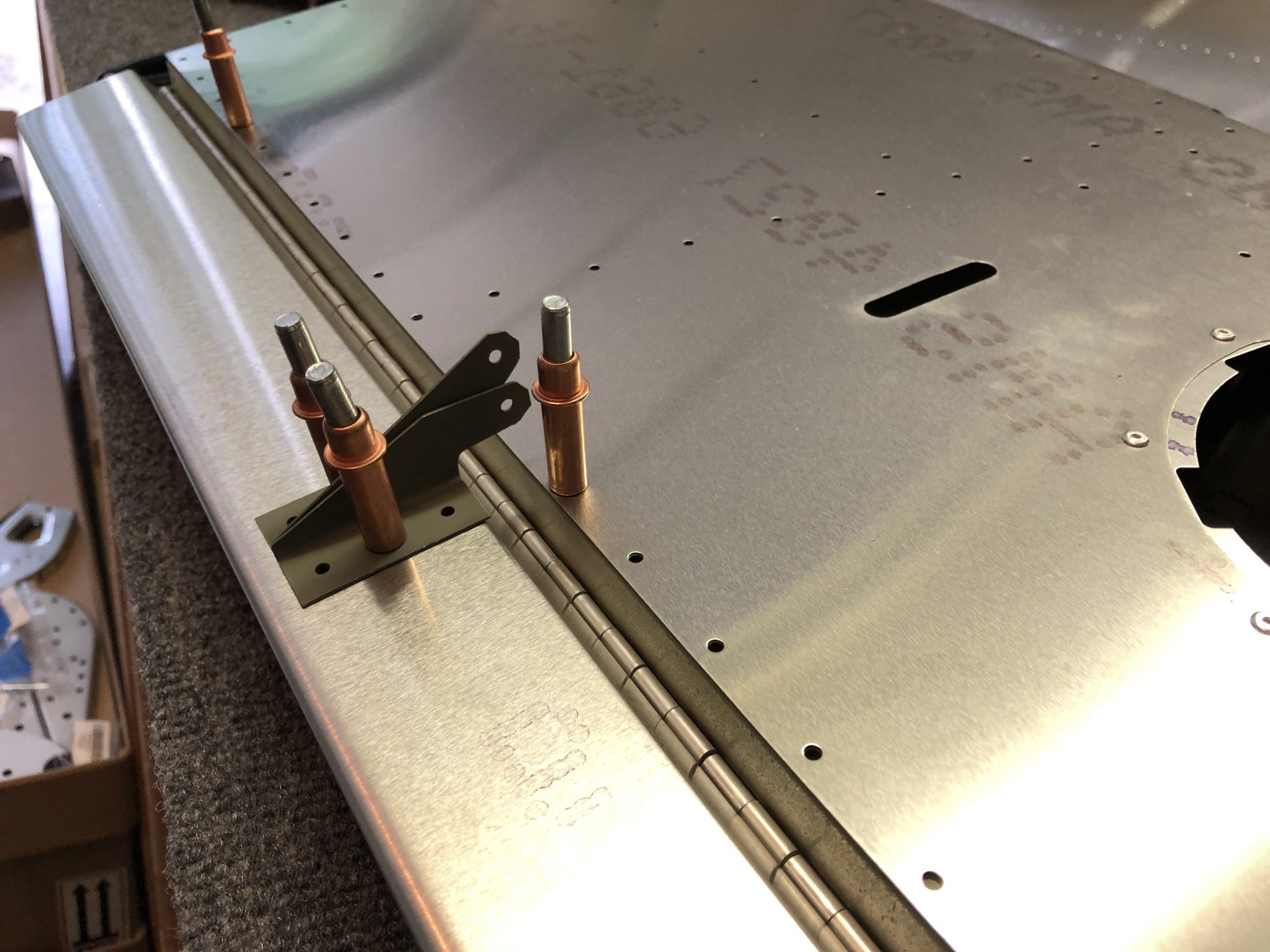
Here are a couple of pictures of the first circle I cut – note that briefly I had the pivot point jump out of the hole, which caused me to waver a bit which you can see towards the bottom where it’s not perfectly round, so make sure the pivot continues to stay in the hole.
Annotated video of the process of cutting the hole
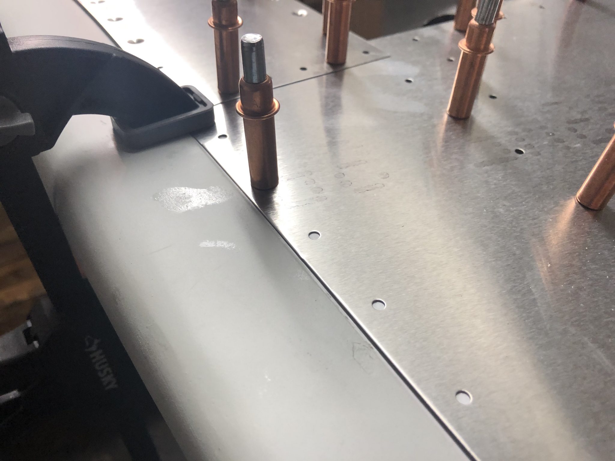
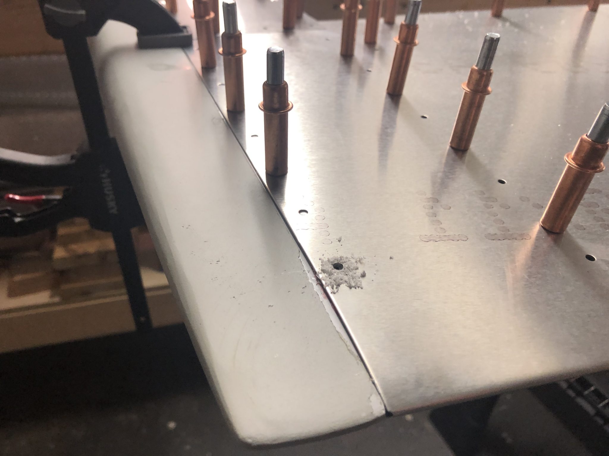
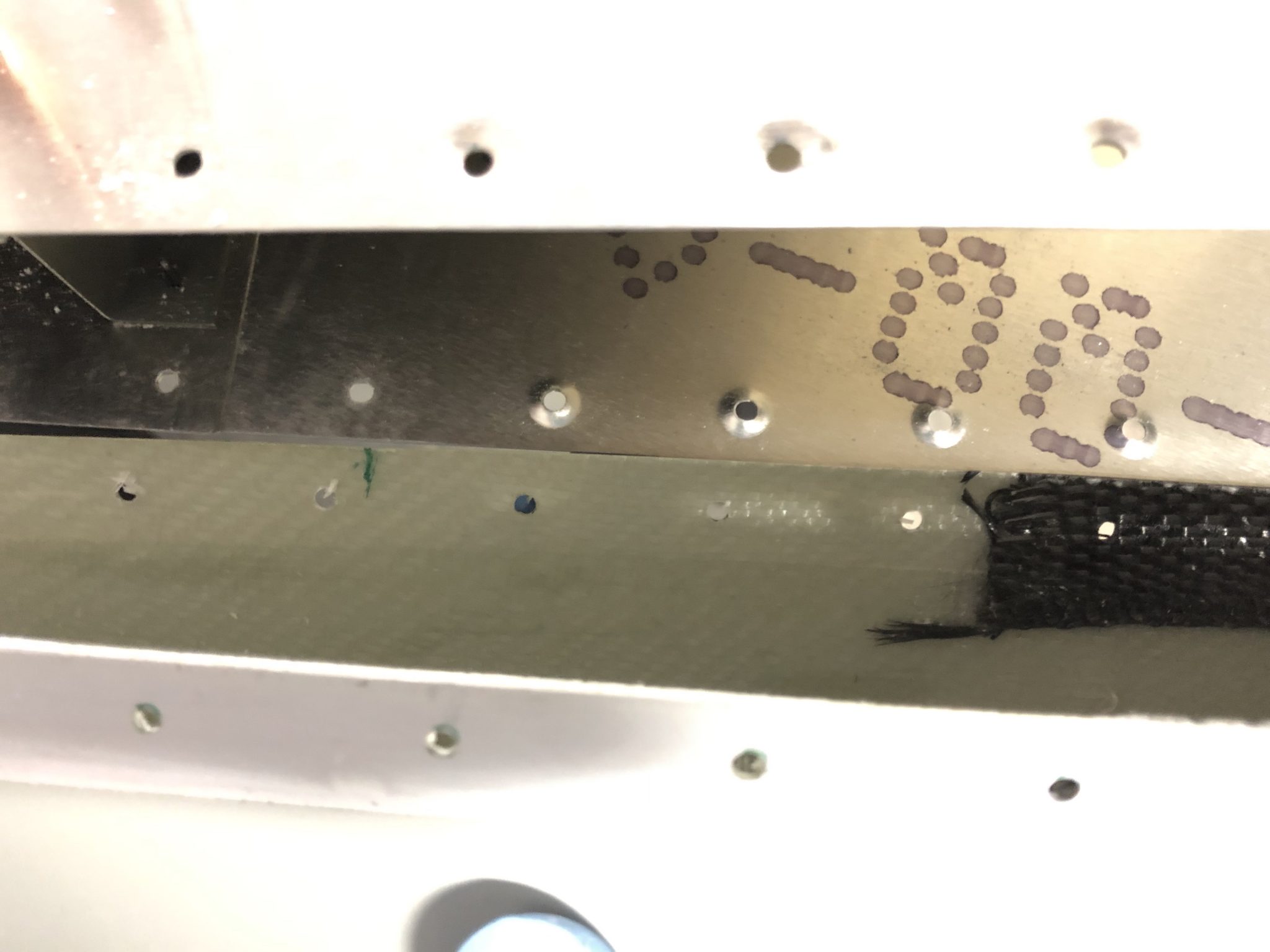
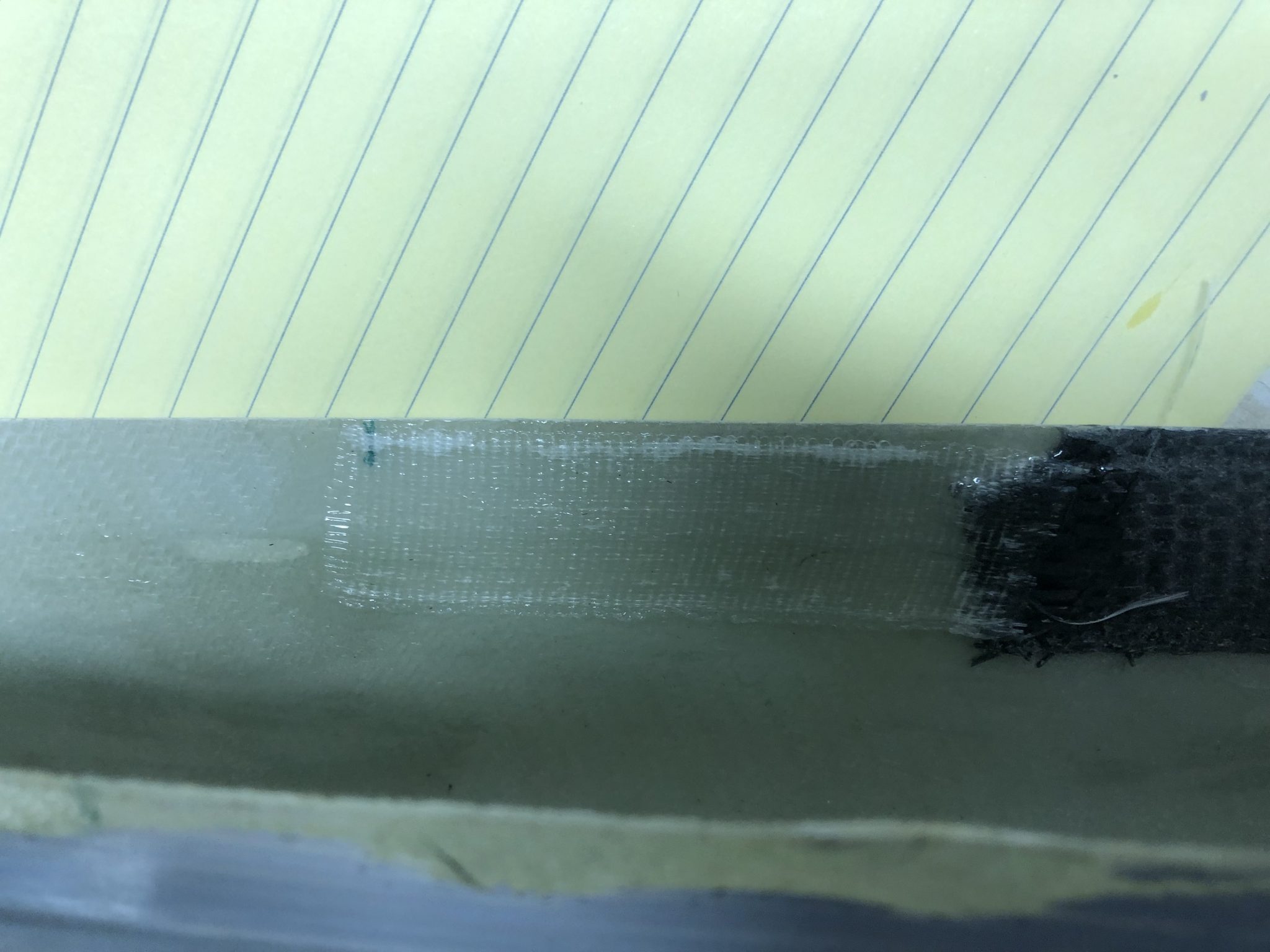
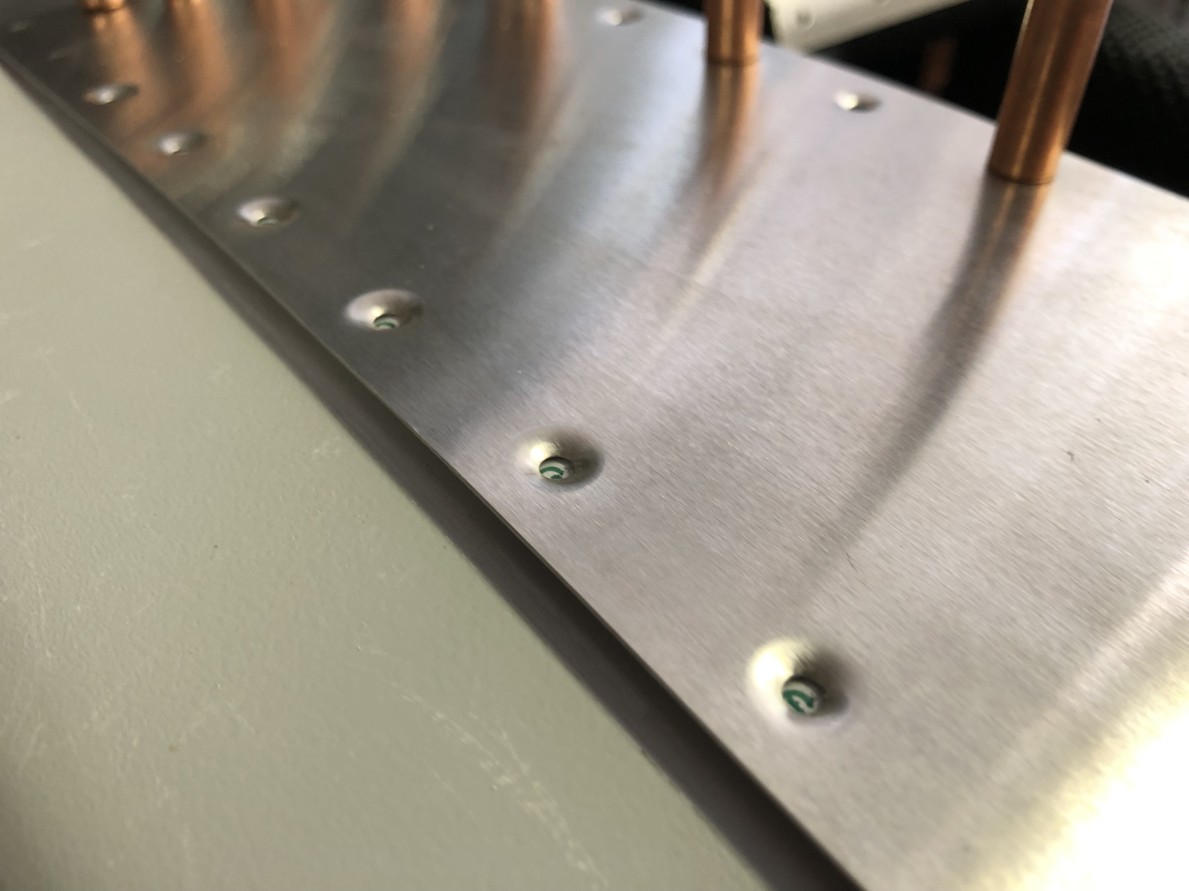
The leading edges of the Elevator Fiberglass tips have flush rivets and so they need to be countersunk. The parts that need to be countersunk are reinforced to add thickness, but the reinforcements on my fiberglass tips wasn’t long enough, so I had to add some more so I can finish them.
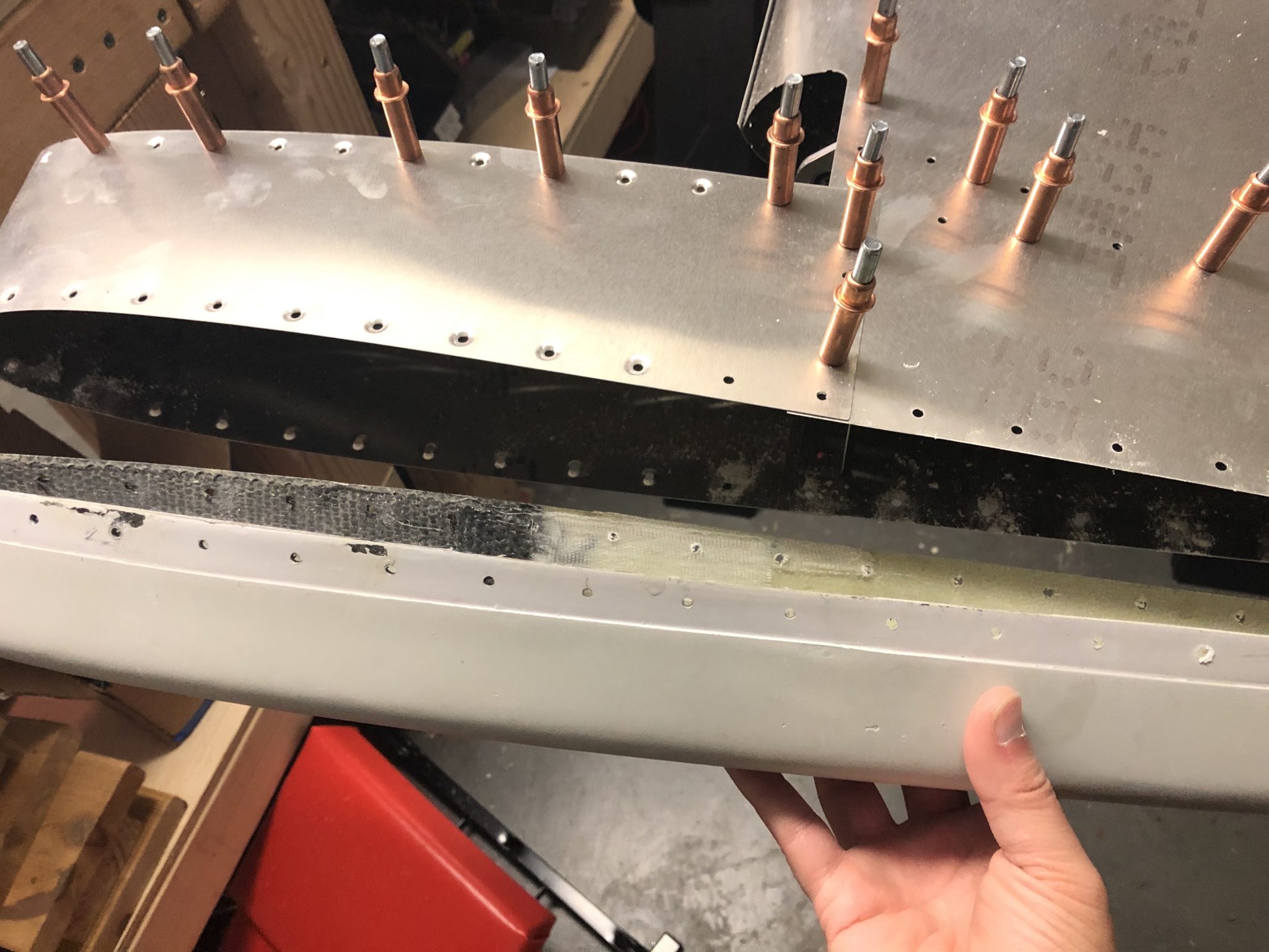
As you can see in the picture below, the black reinforcement doesn’t go far enough for the last two rivets on the left that are also dimpled flush.
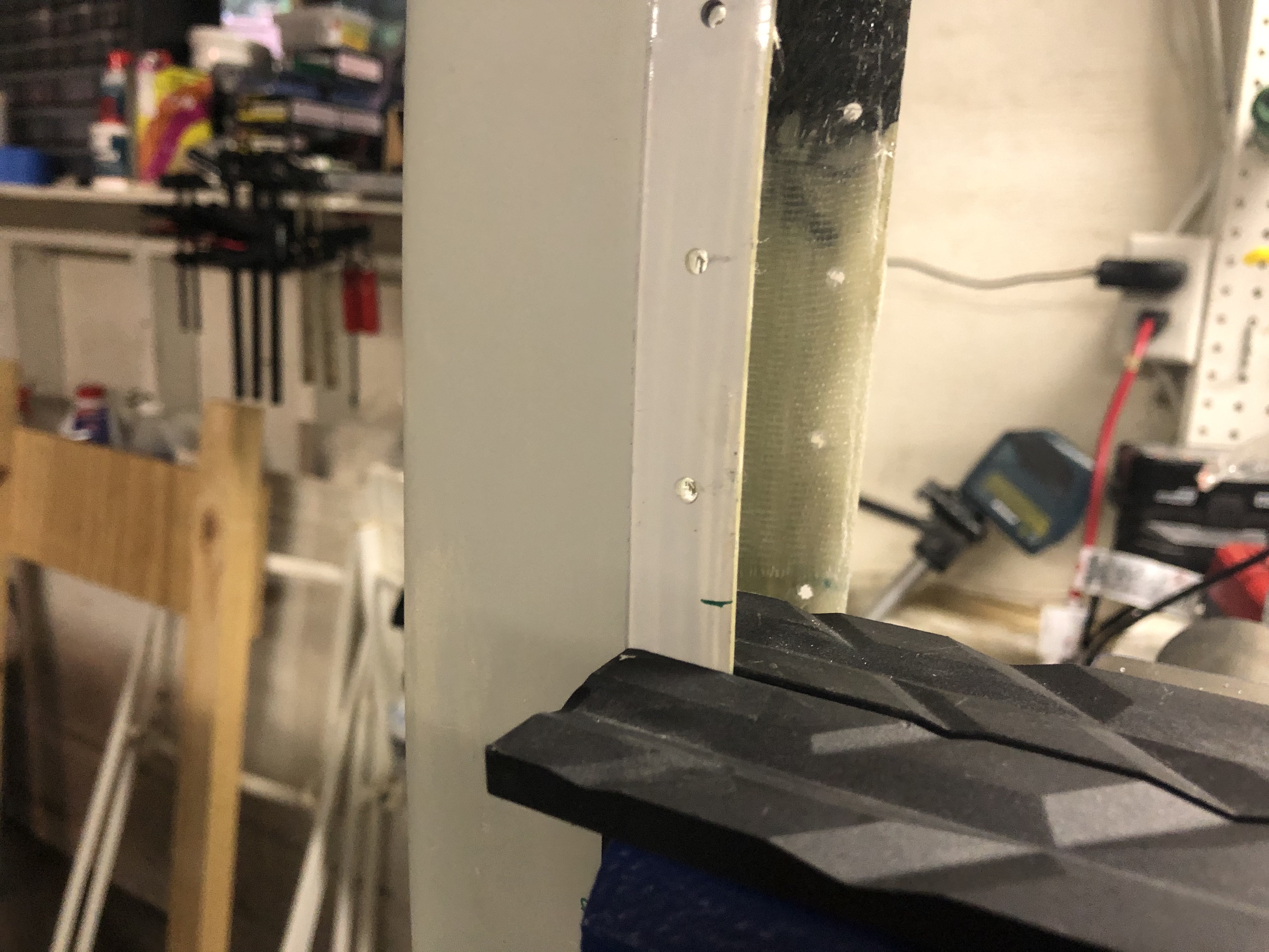
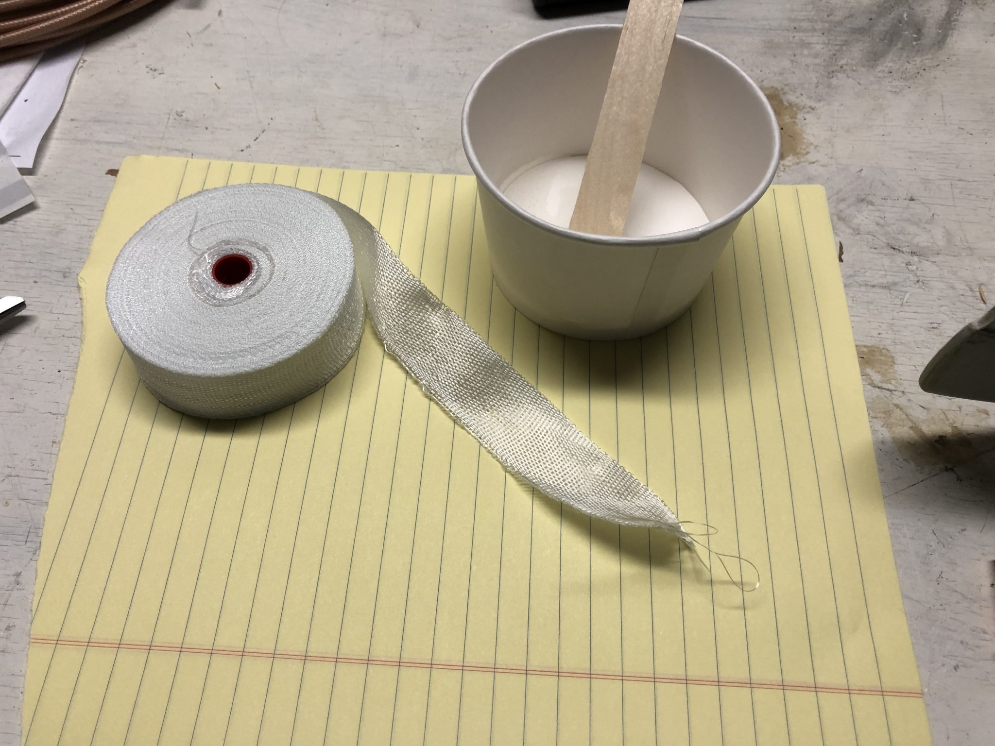
I got some one inch wide fiberglass cloth tape and mixed some epoxy to extend the area that needs reinforcement. I marked out how far I needed to extend and cut strips of the fiberglass cloth to size to apply.
A few layers applied and set out to dry for a few hours and then I can countersink the holes.
It’s been a busy few weeks after returning from Oshkosh, so it’s been a while since I’ve written an update.
Since I spent the whole week at Oshkosh, I had a lot of time to figure out various bits and pieces that will go into the airplane and talk to the various vendors. I also finally got to meet Adam and Steve from Midwest Panel Builders who I’m working with for the Avionics.
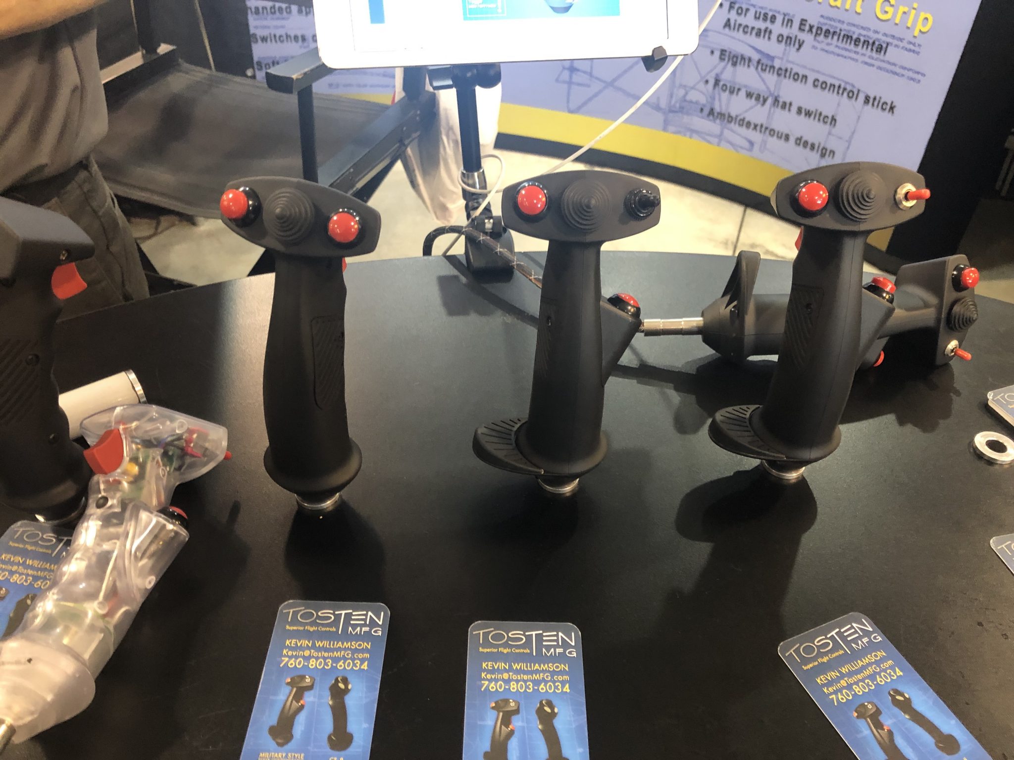
It was great to get a feel for various things including the control sticks – I will go with the Tosten grip.
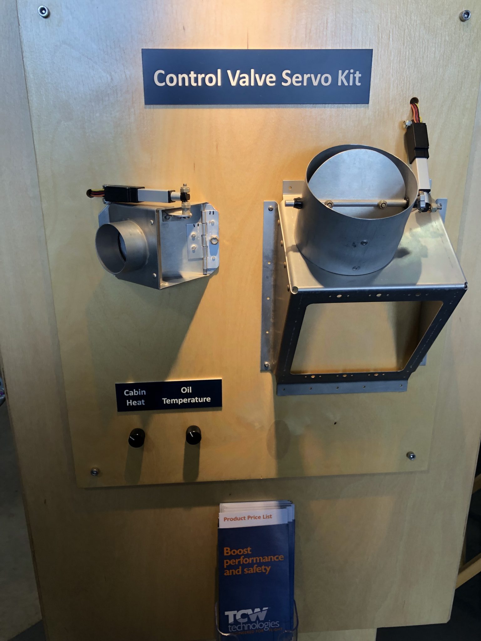
Another thing I was looking at is the TCW Control Valve servo for the vent shutoff valve that the TSi has. The standard design for this is a physical shutter that I’m not a great fan of, as I feel it looks a bit out of place in the panel. So I was looking for alternative options and Adam mentioned this servo as a possible option. After I checked it out, I think indeed it might be a nicer solution and I will try to make it work. In fact I might also use it for the heating control.
Aside from figuring out things for my own build, I also attended a lot of seminars, saw a lot of cool airplanes and the airshows and met a lot of interesting people and stories.
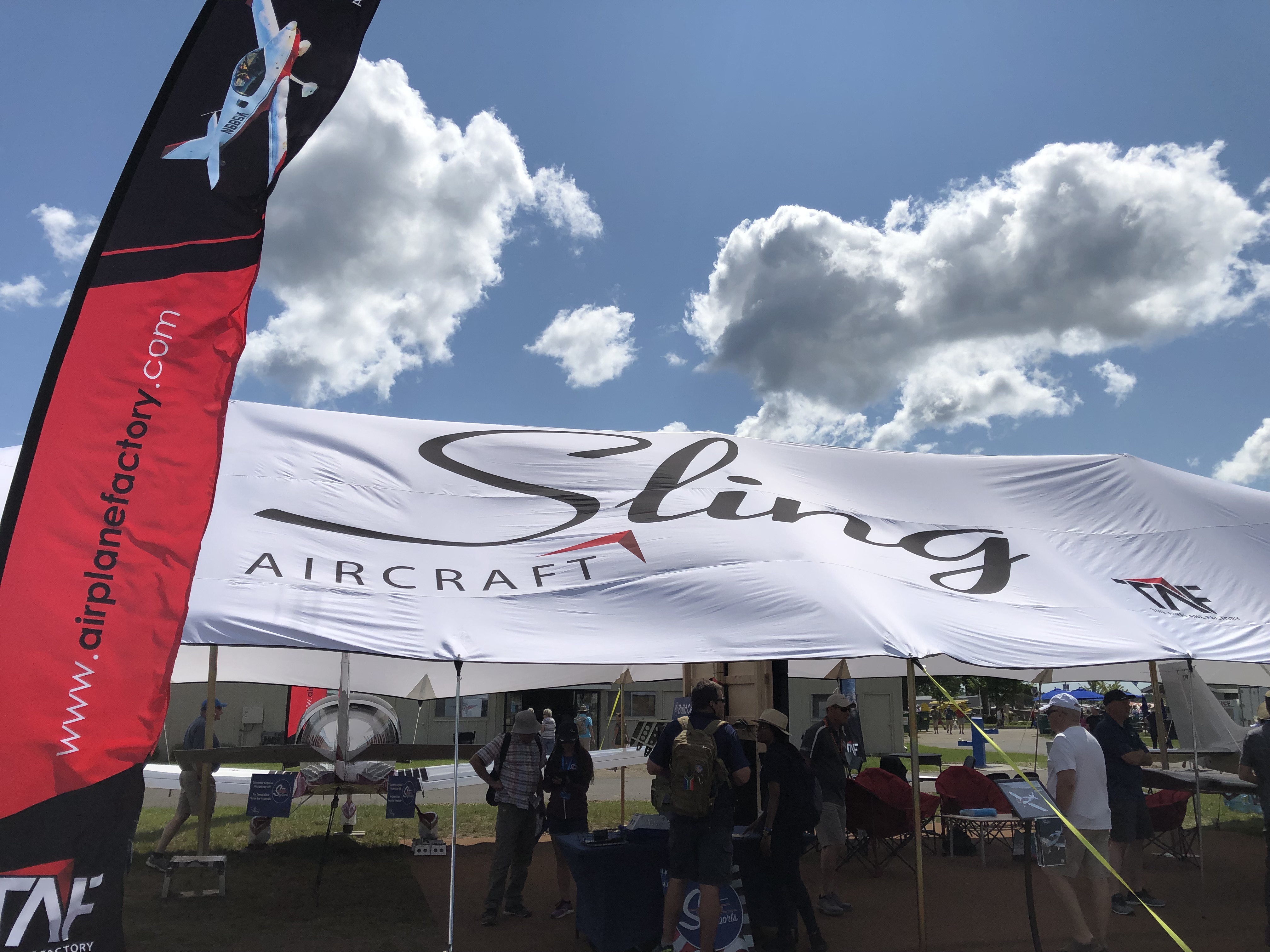
I also spent a lot of time lurking around the Sling tent and checking out various details of the completed Sling TSi that they had on display there. It was nice to see how a lot of the small details to the plans for the fit and finish were in this plane, which didn’t exist in Wayne’s TSi yet.
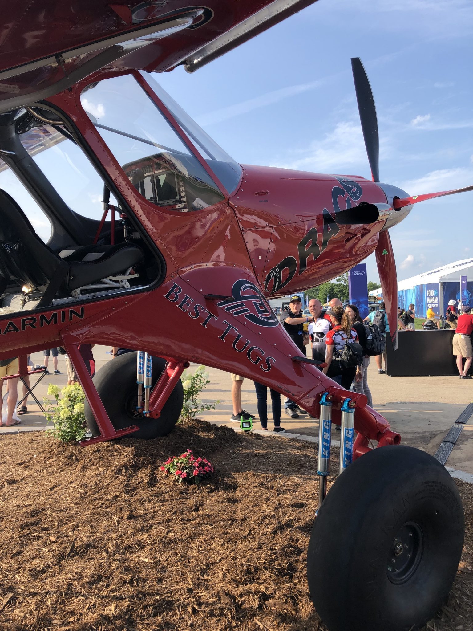
I was also able to meet a few of the other Sling builders at the Sling Ding meeting and had a long chat with Craig and Austin about our various builds. And I got to meet John & Marta King who I have to give credit to getting me through the ground school of my private and instrument training and ran into a few other people including Angle of Attack, Aviation 101, Jason Miller, JP The Candourist and Mike Patey and Draco the bush plane.
With the two main skins fitted onto the Elevator, I started looking at the trim tab and the side fiberglass tips.
First I figured out the correct orientation of the hinge that connects the Elevator and the trim tab and the right orientation of the trim tab. I temporarily clecoed them together to check that the clearances are good and it moves all fine.
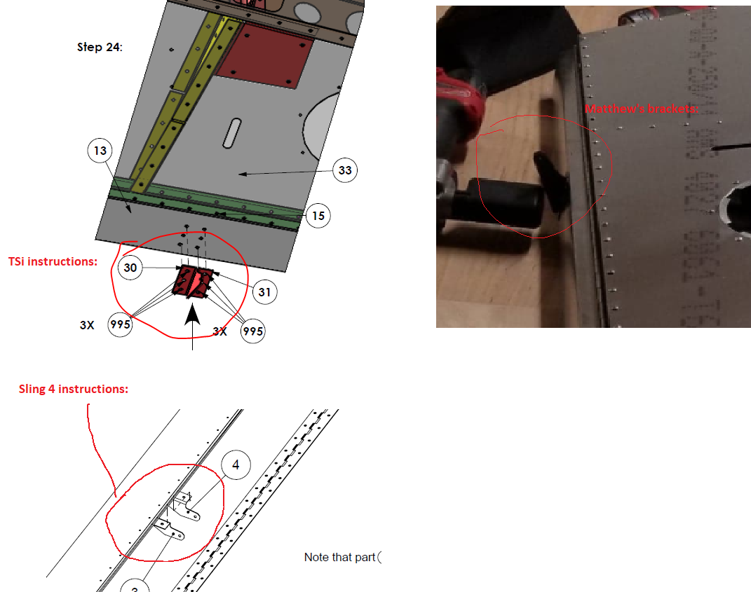
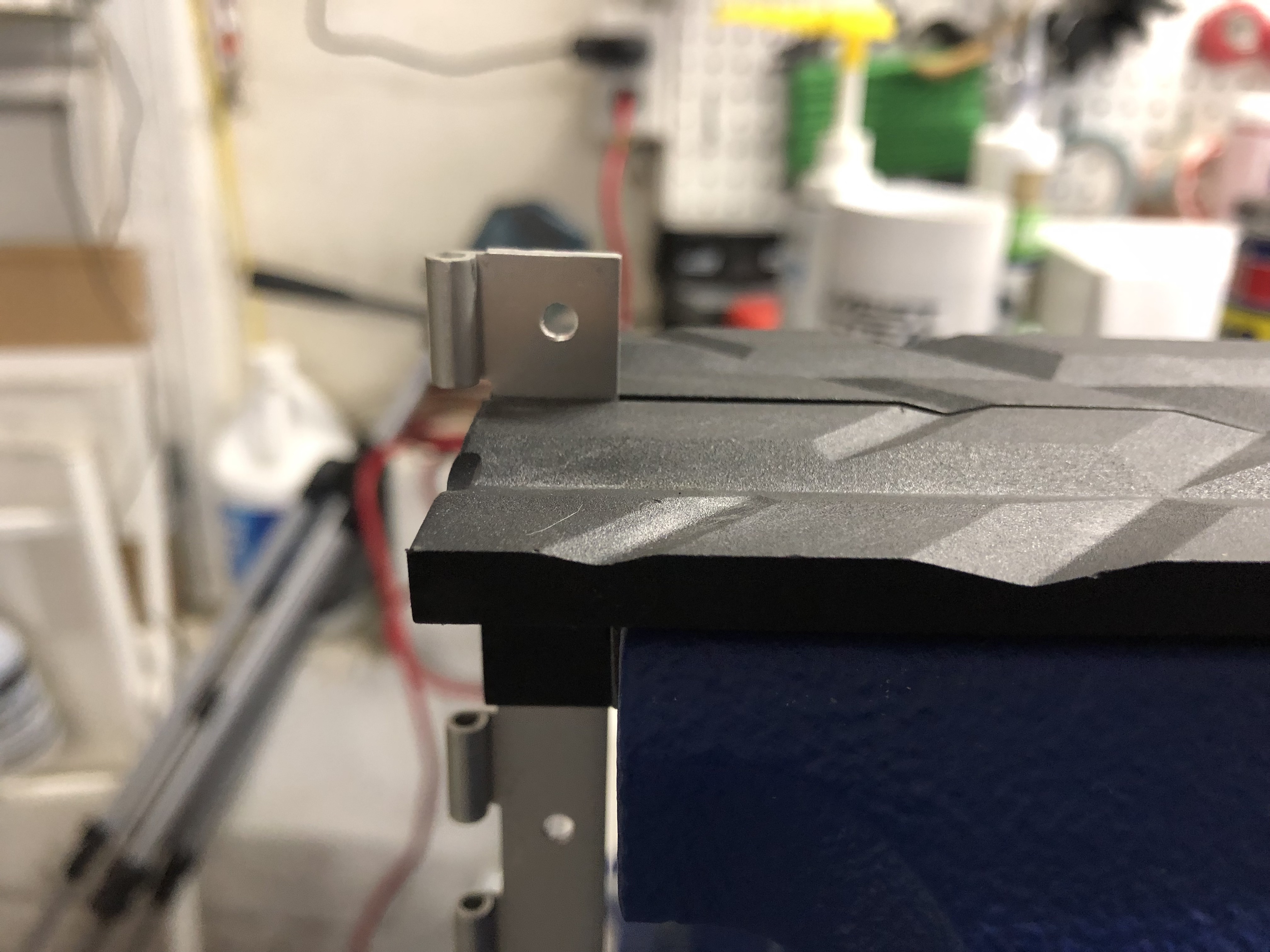
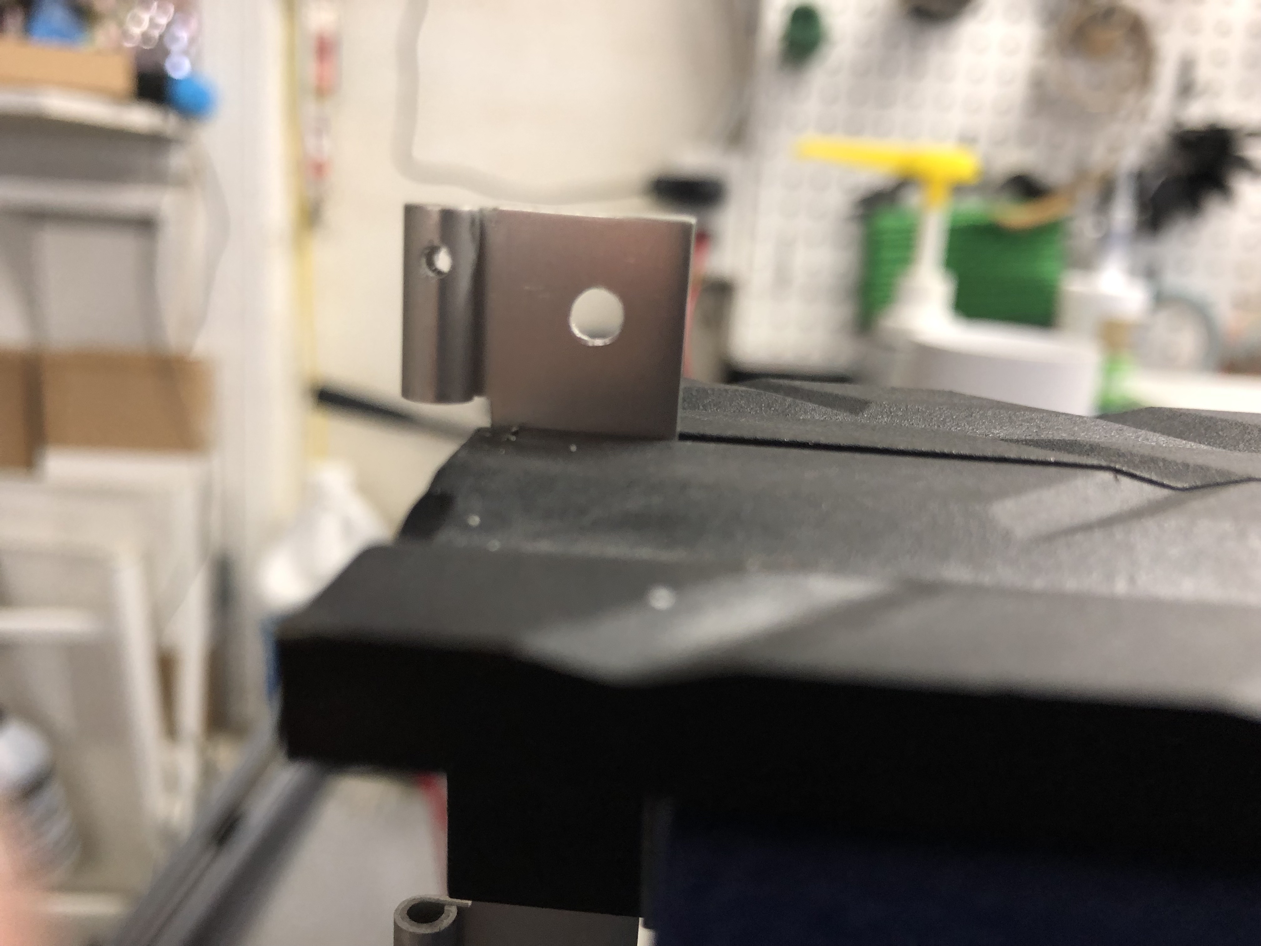
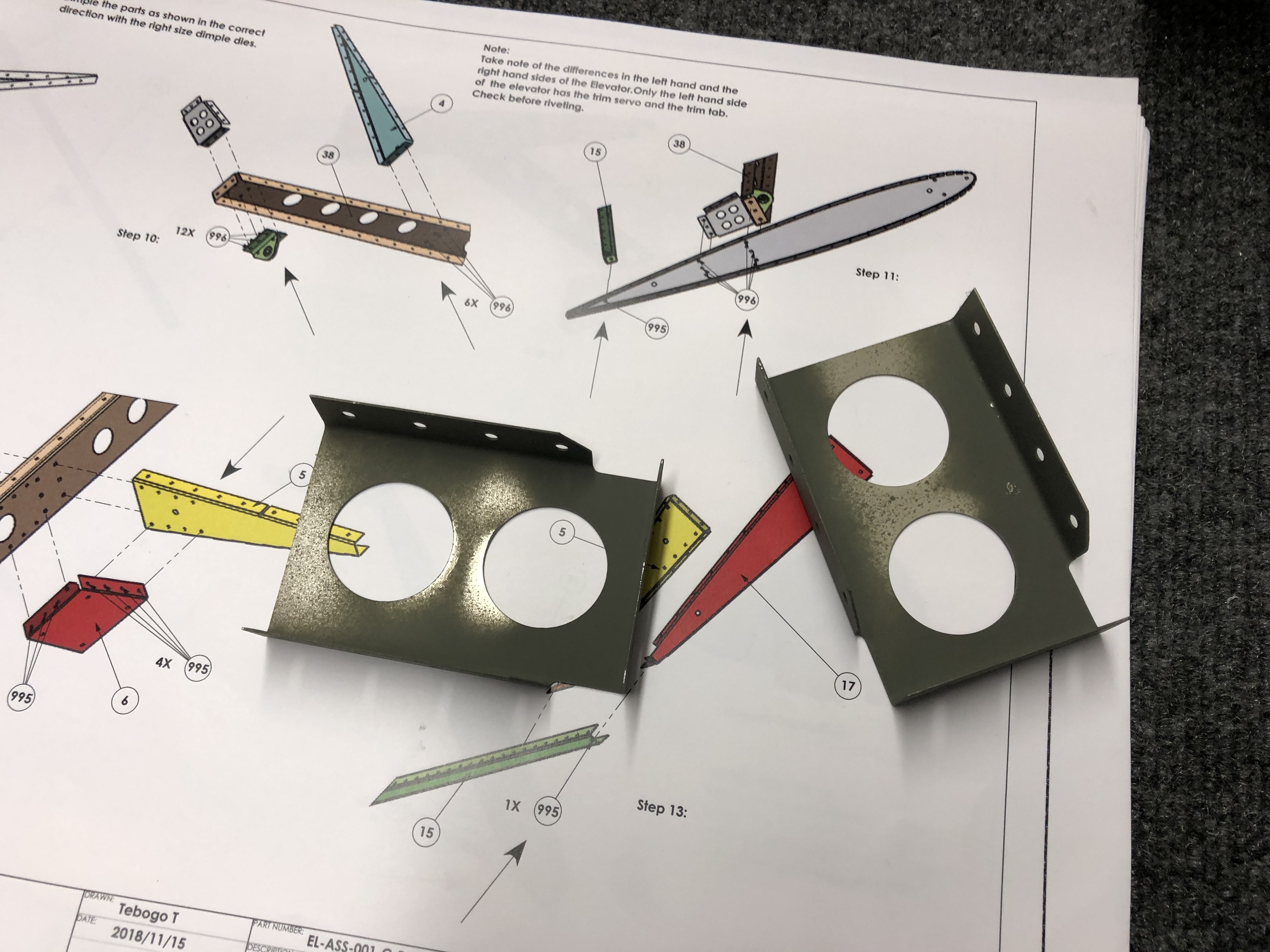
Then I was searching for the brackets that go on top of the trim tab and realized that I got two different looking brackets. Since this looked off to me, I tried to squint real hard at the instruction manual to figure out which bracket is the right one. I also checked the Sling 4 instructions and asked Matthew if he had a picture of his brackets and with that figured out that I must have received one TSi and one Sling 4 bracket, so I put in a note with the factory so I can get the right bracket for my TSi.
Securing the trim tab piano hinge
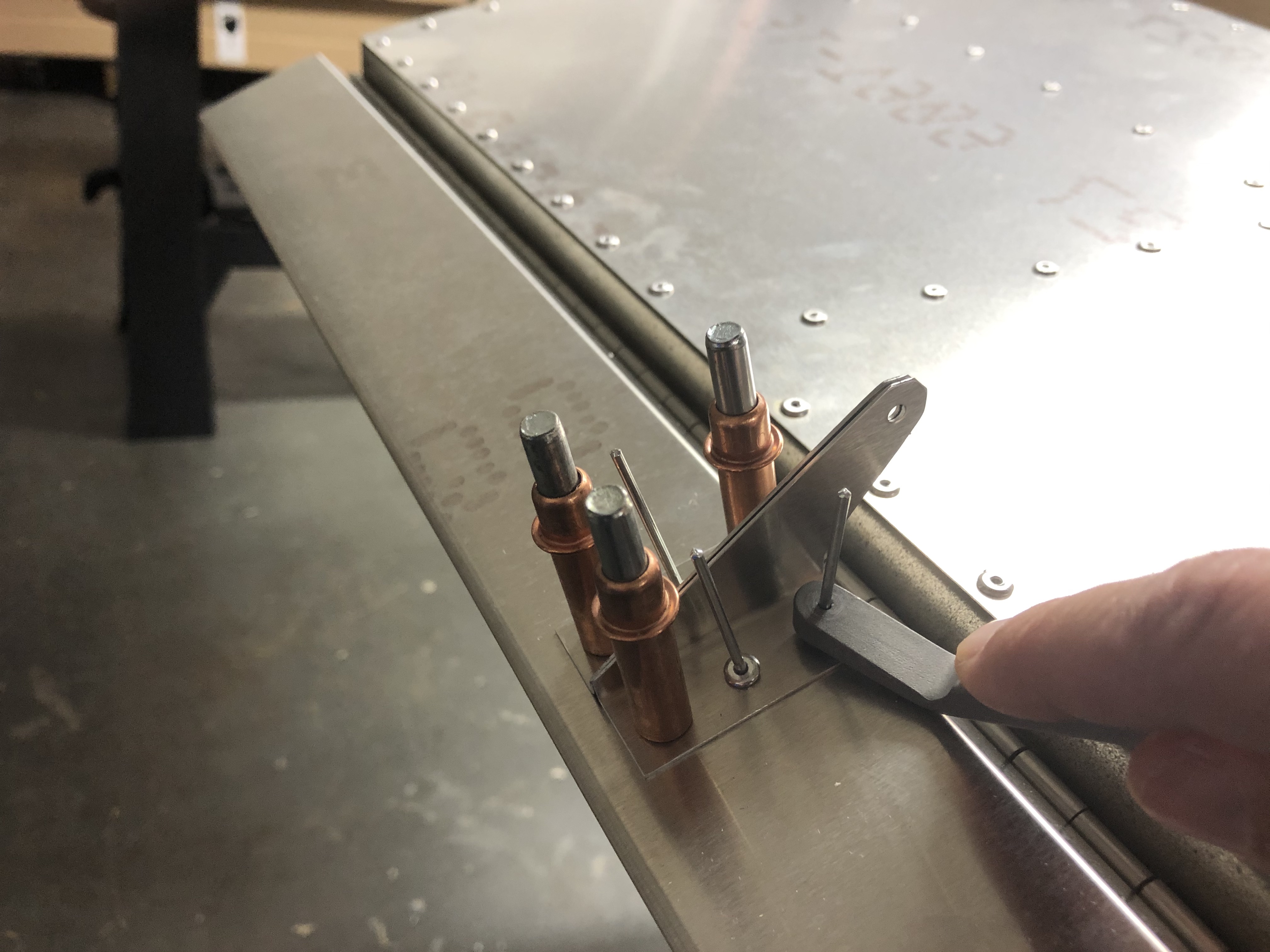
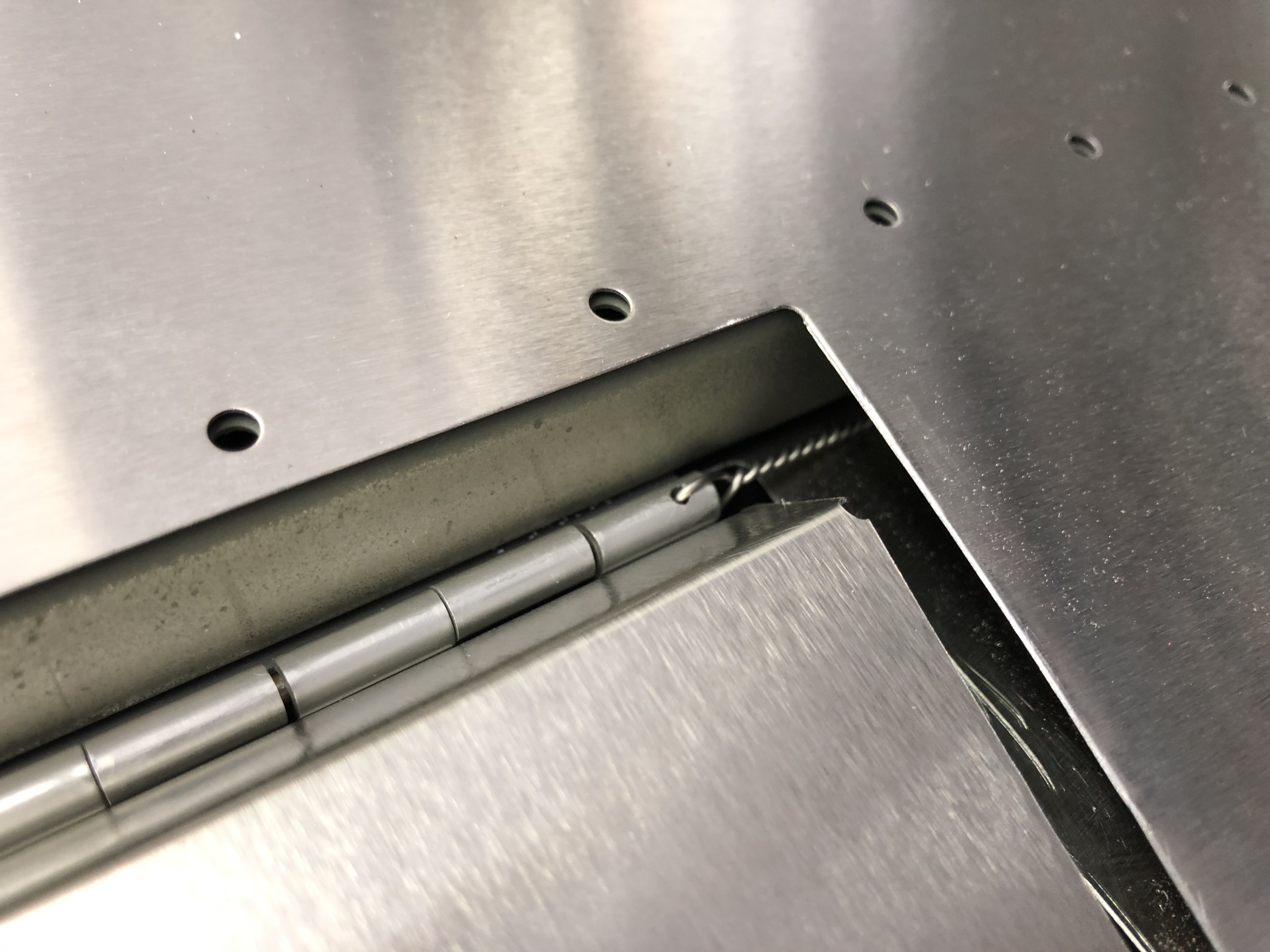
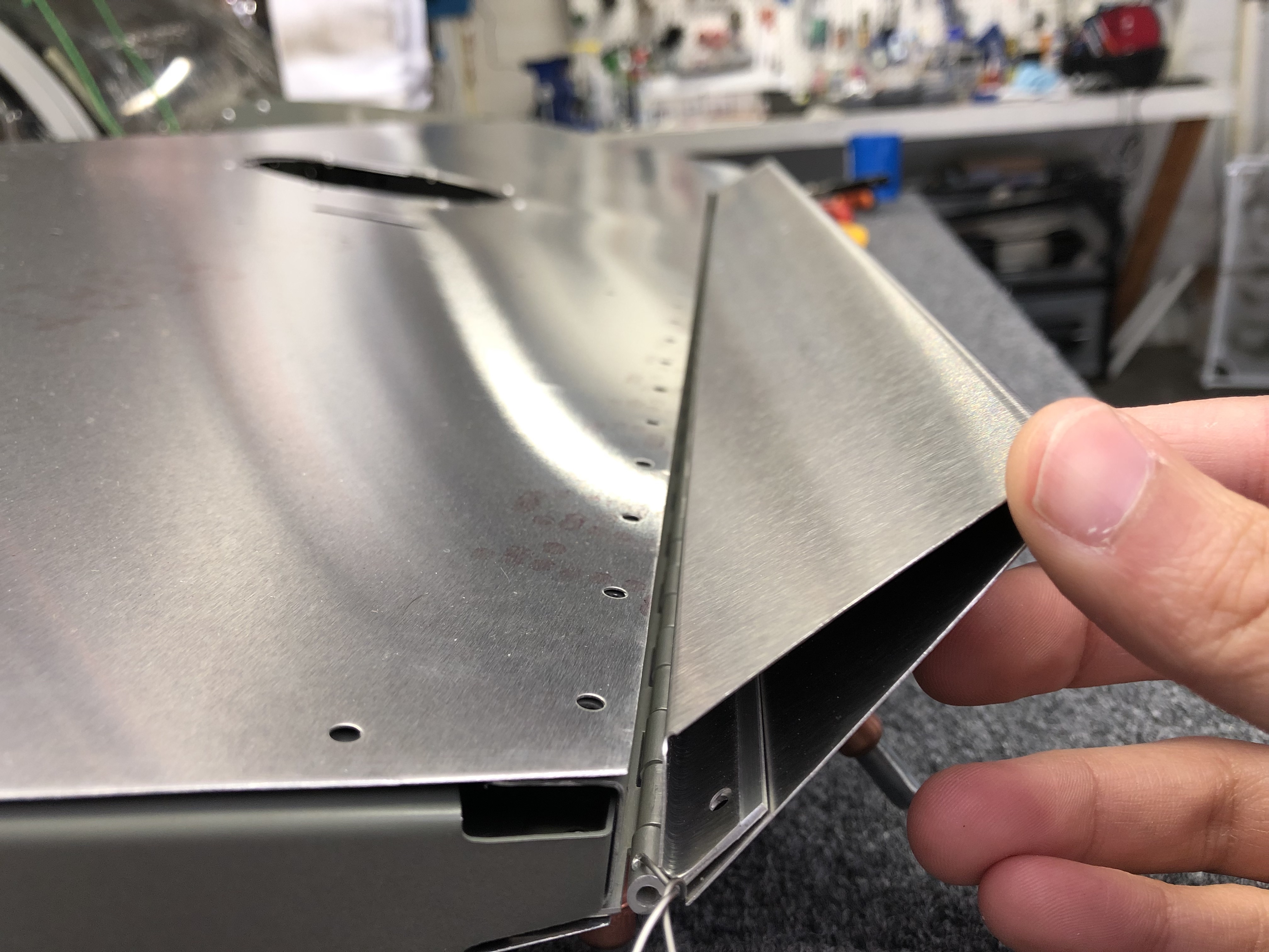
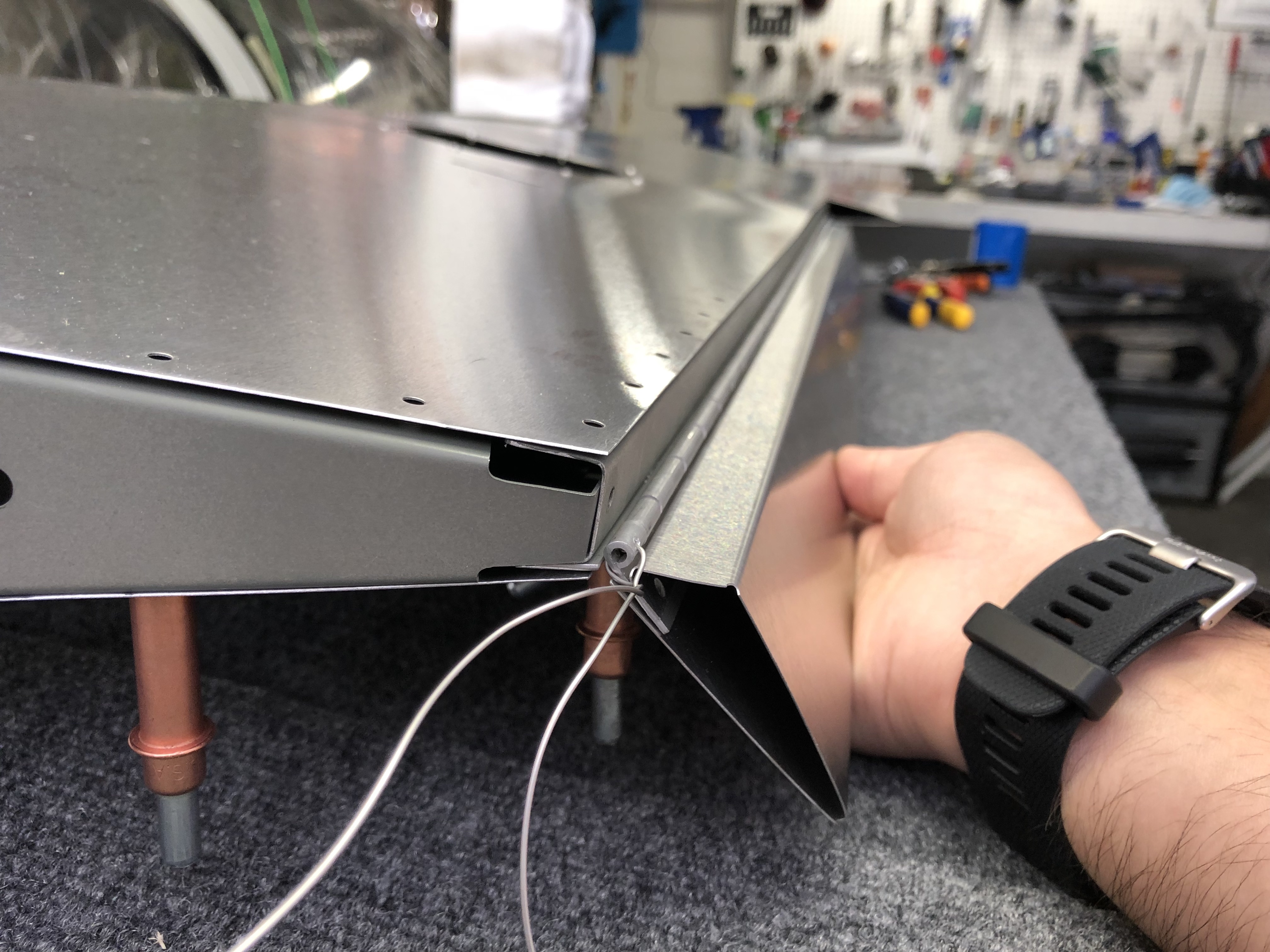
With that out of the way, I focused on thinking about securing the piano hinge that attaches the trim tab to the elevator. Since there is no natural stop for the pin that goes through the hinge on either side, it could happen that it becomes lose from vibration and thus could come out during flight, which would be bad. I research a bit on the topic and found this article from EAA on the use and installation of piano hinges.
One of the ways to secure the hinge is to drill a small hole through the last part of the hinge and install a safety wire. My hinge was luckily cut in a way that makes this approach very easy to achieve. I got out a small drill bit, mounted the hinge in my bench vise and drilled a hole on each side so I could run a safety wire through it.
Using the safety wire approach makes it easy to still remove it in the future, but ensures that the pin stays securely in the hinge.
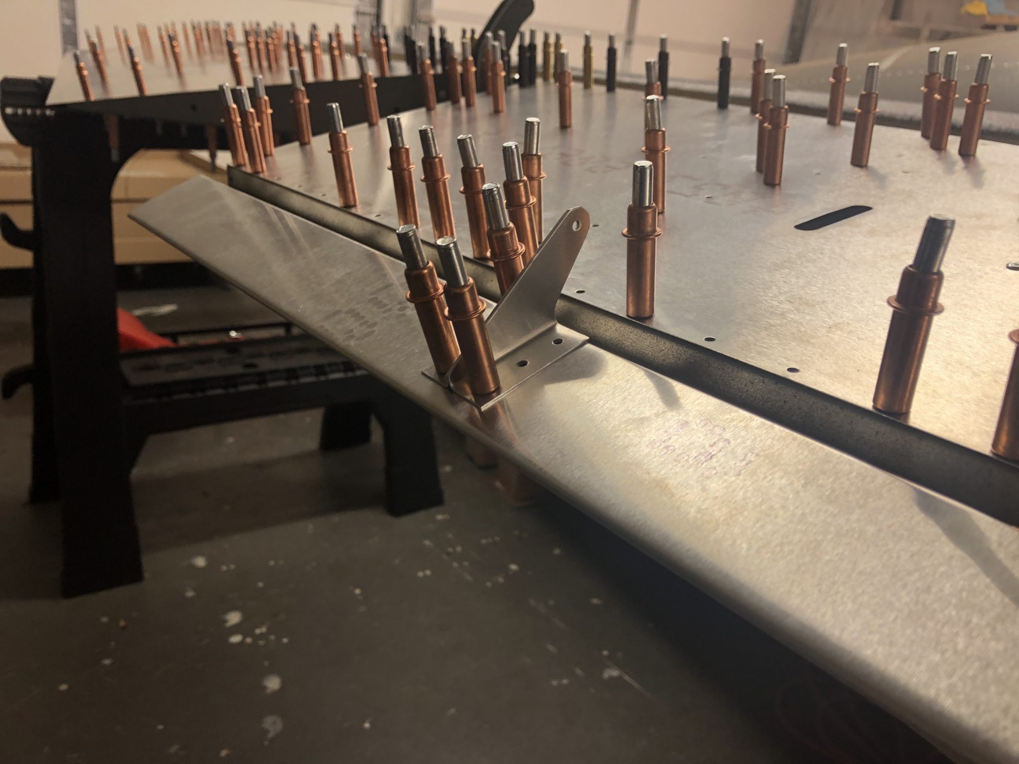
Fitting the left side fiberglass tip
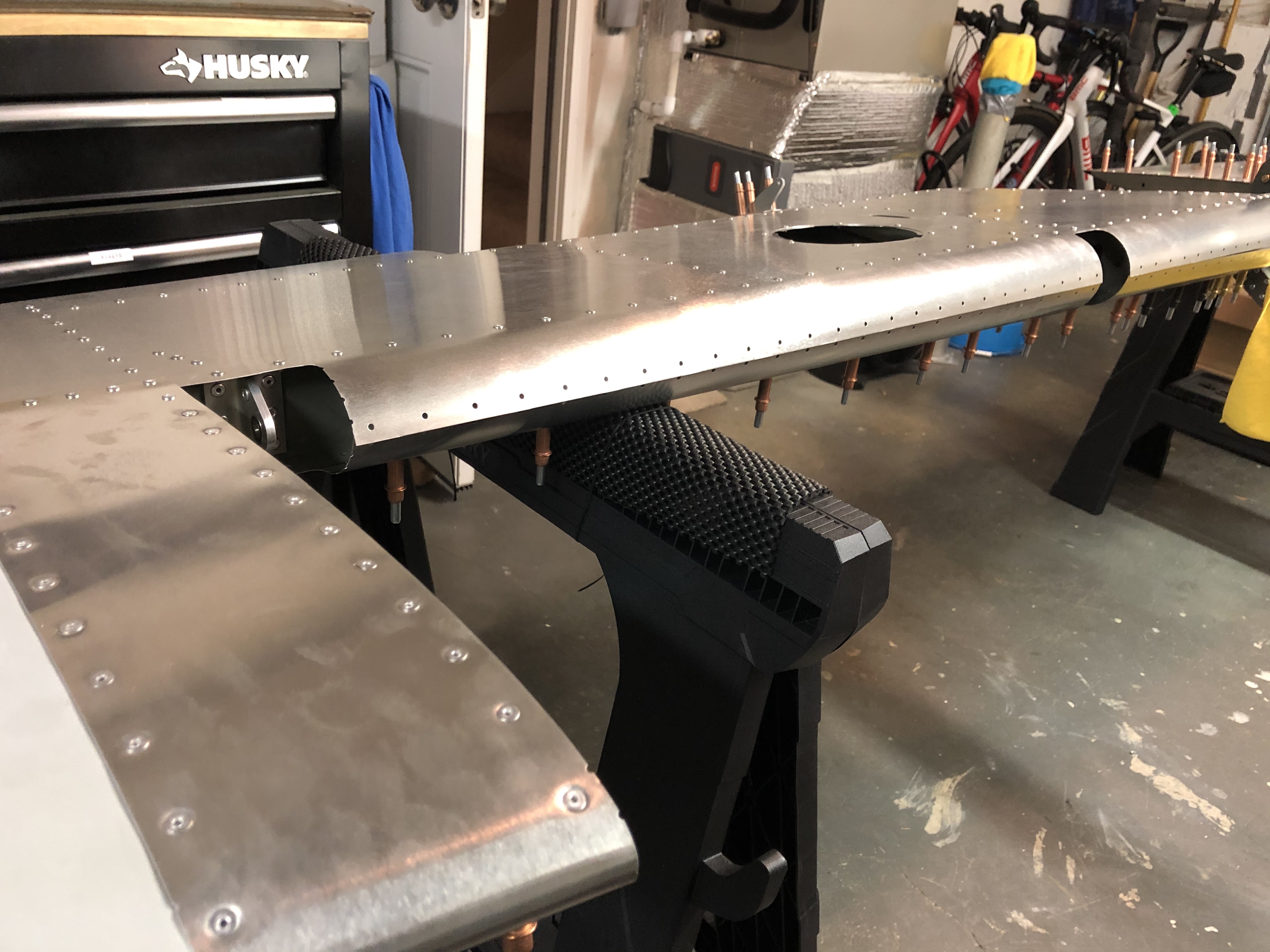
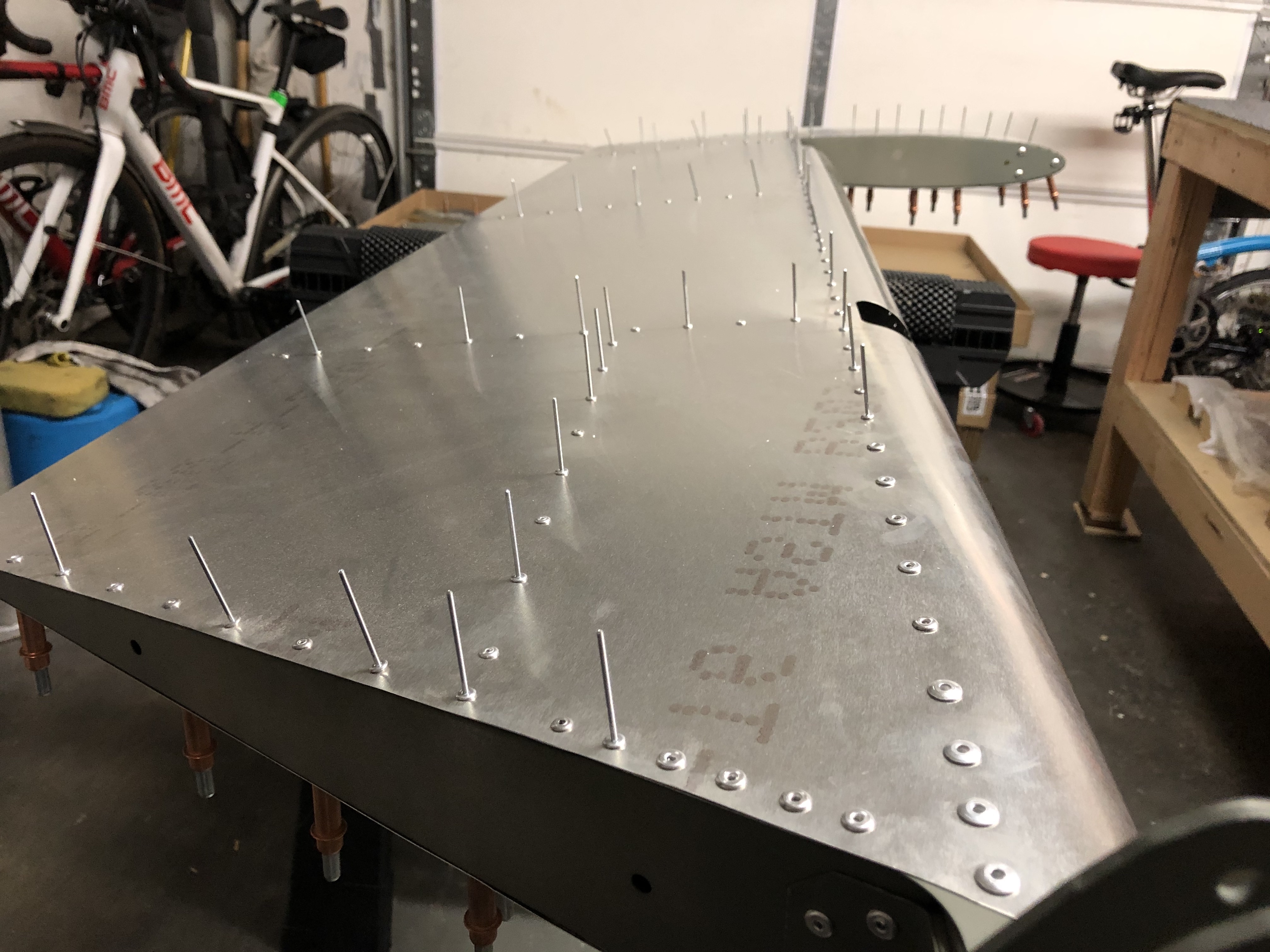
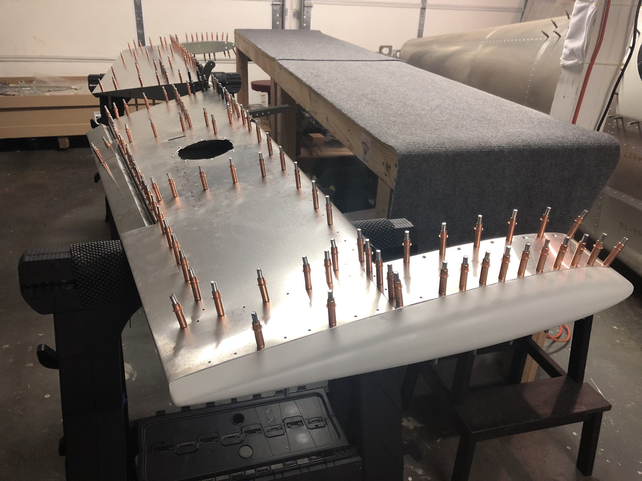
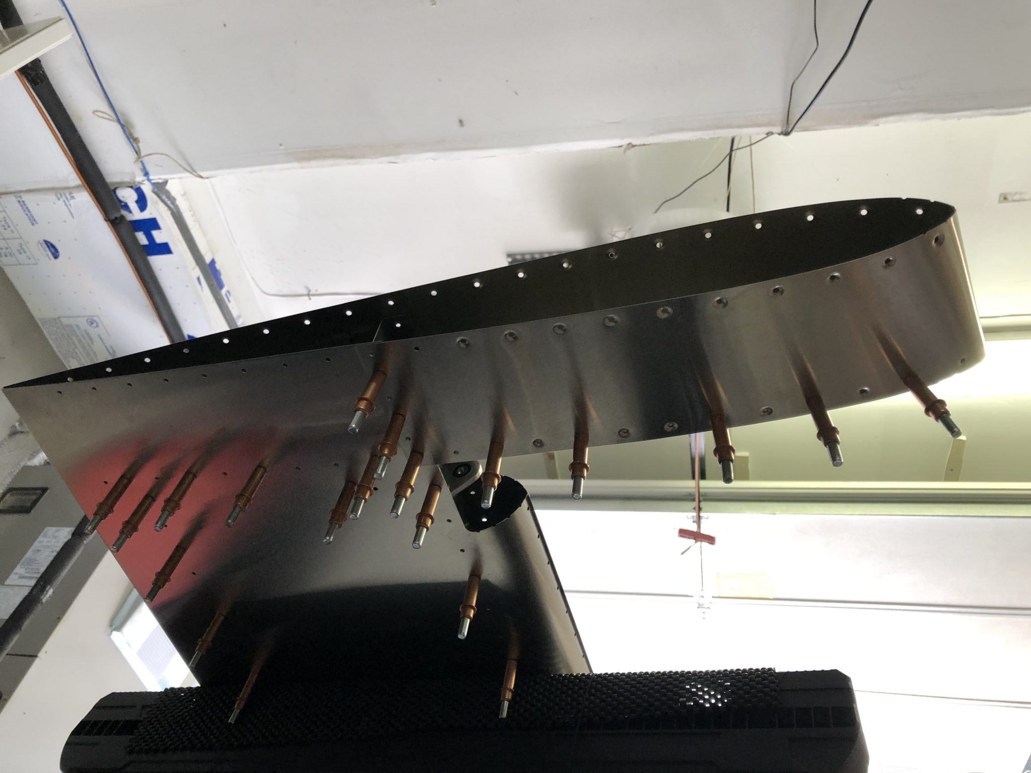
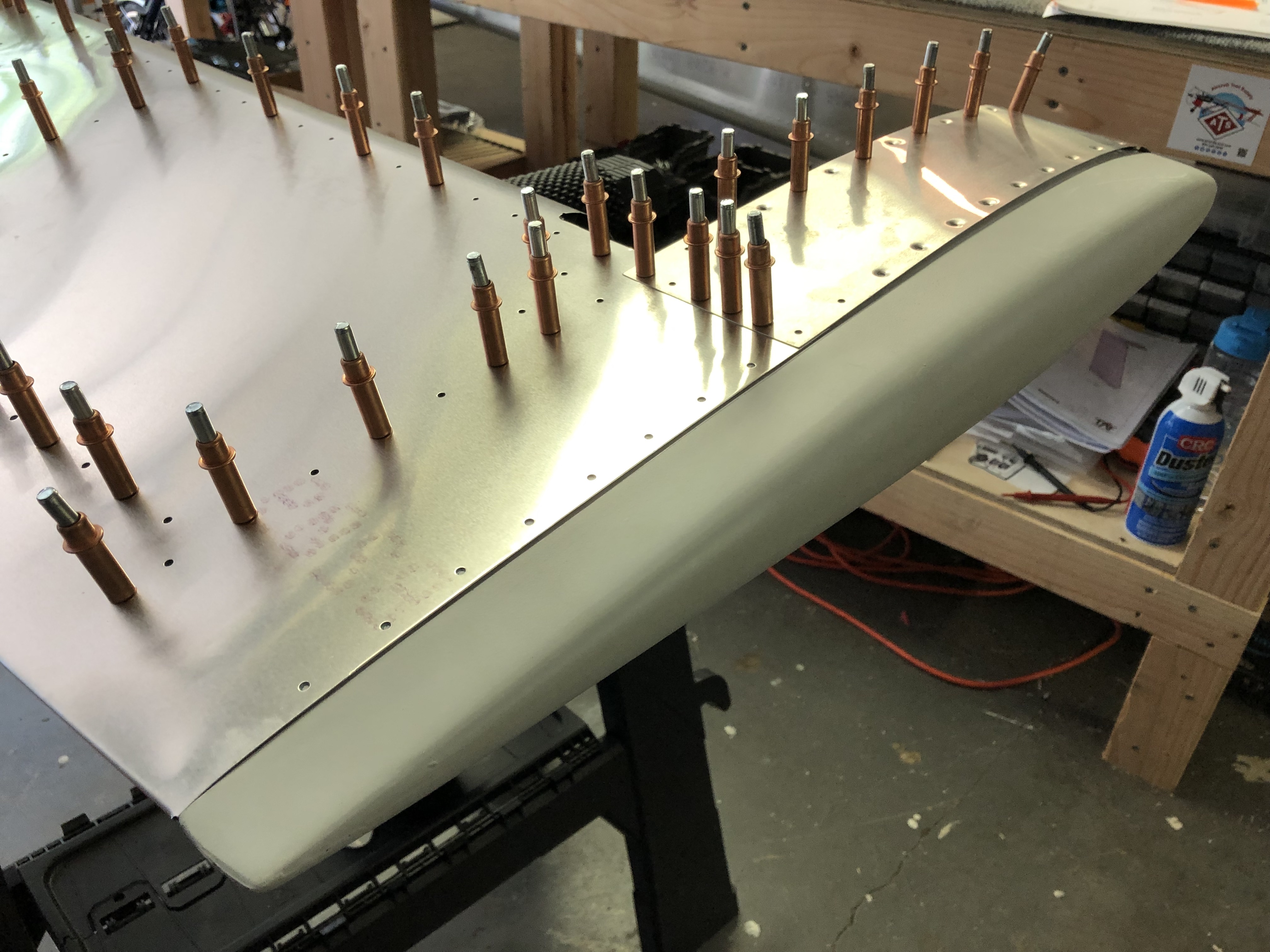
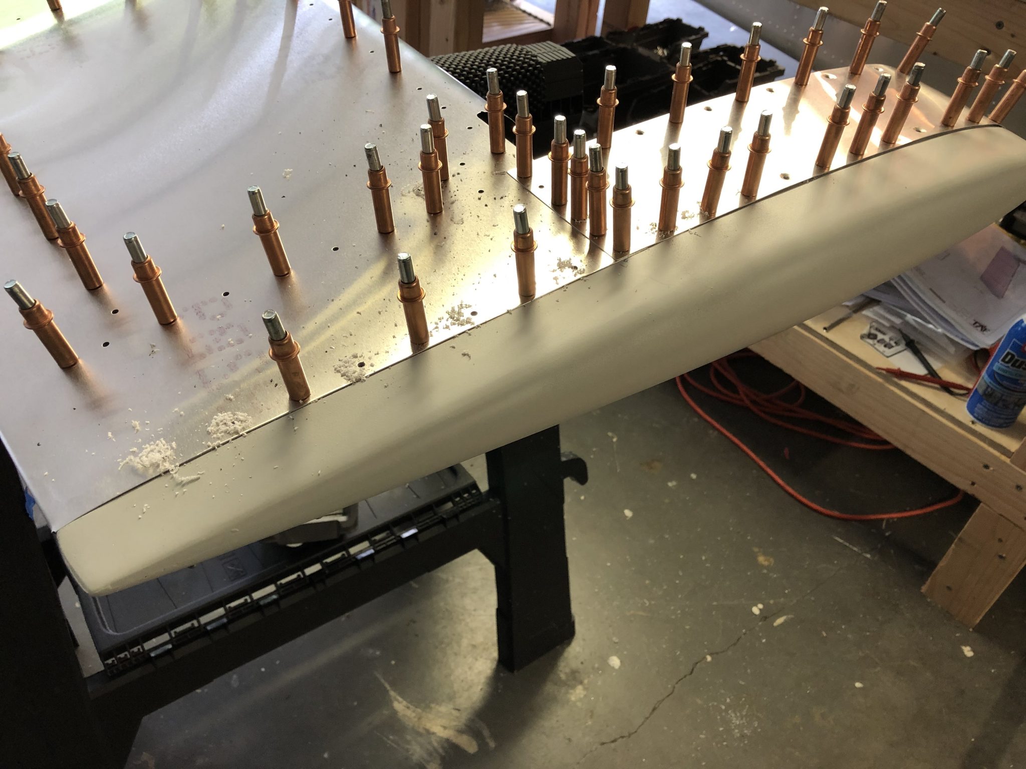
For the last part of the day, I started on fitting the last part of the skin and the fiberglass tips. Since this requires moving around the tip from both sides, I moved the Elevator over onto some saw horses so I could access the bottom more easily.
First I clecoed the top skin in place and then I slowly fitted the fiberglass tip in place. In order to get the fiberglass tip to fit, I had to file a tiny bit at the back, but it was much easier than the Rudder tip fitting.
Once I had it in place, I started to hold everything tight together and started match-drilling holes into the fiberglass tip. I used liberal amounts of clecos to get a tight fit and everything looks good. Now I just need to repeat it on the other side.
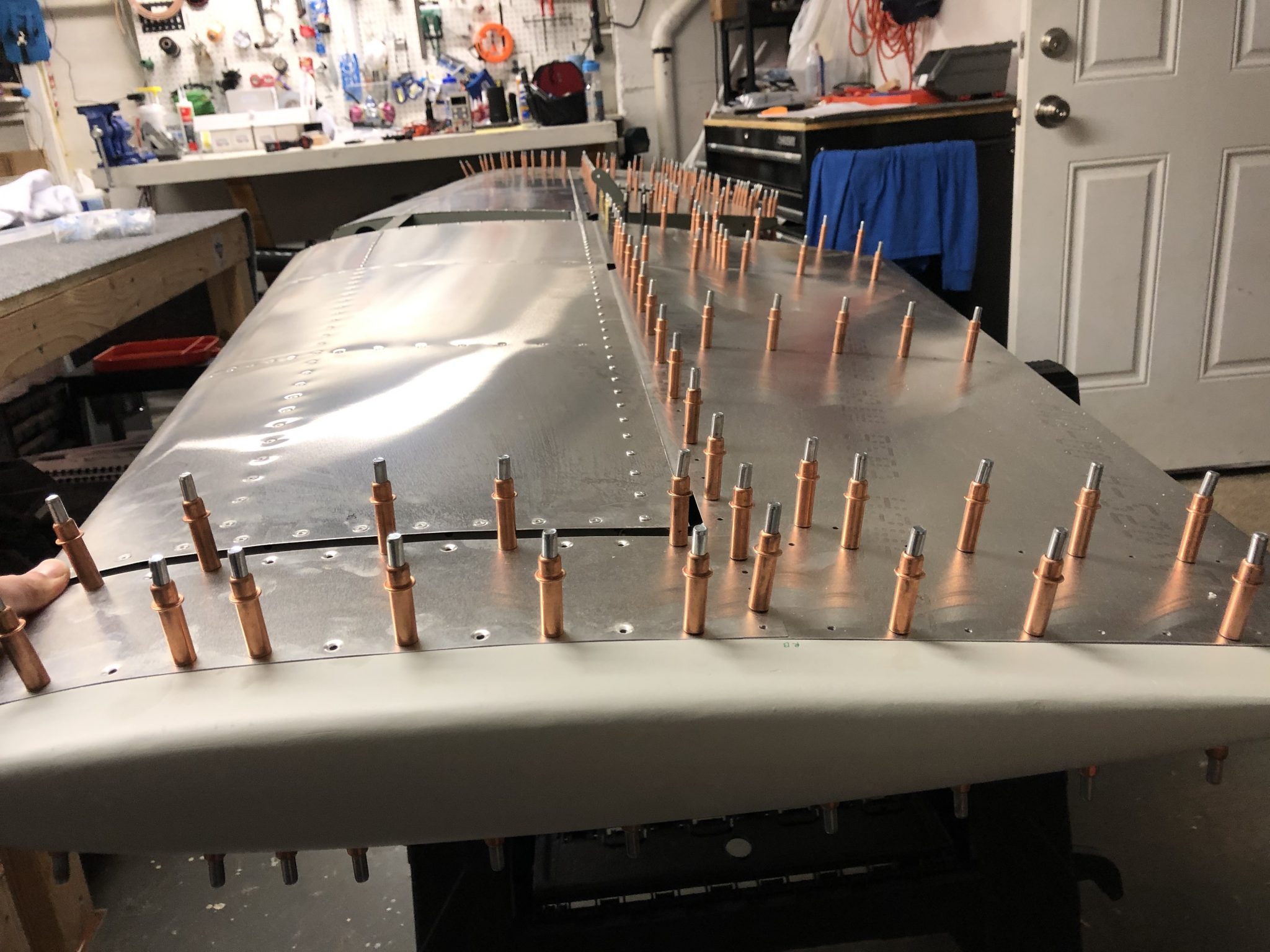
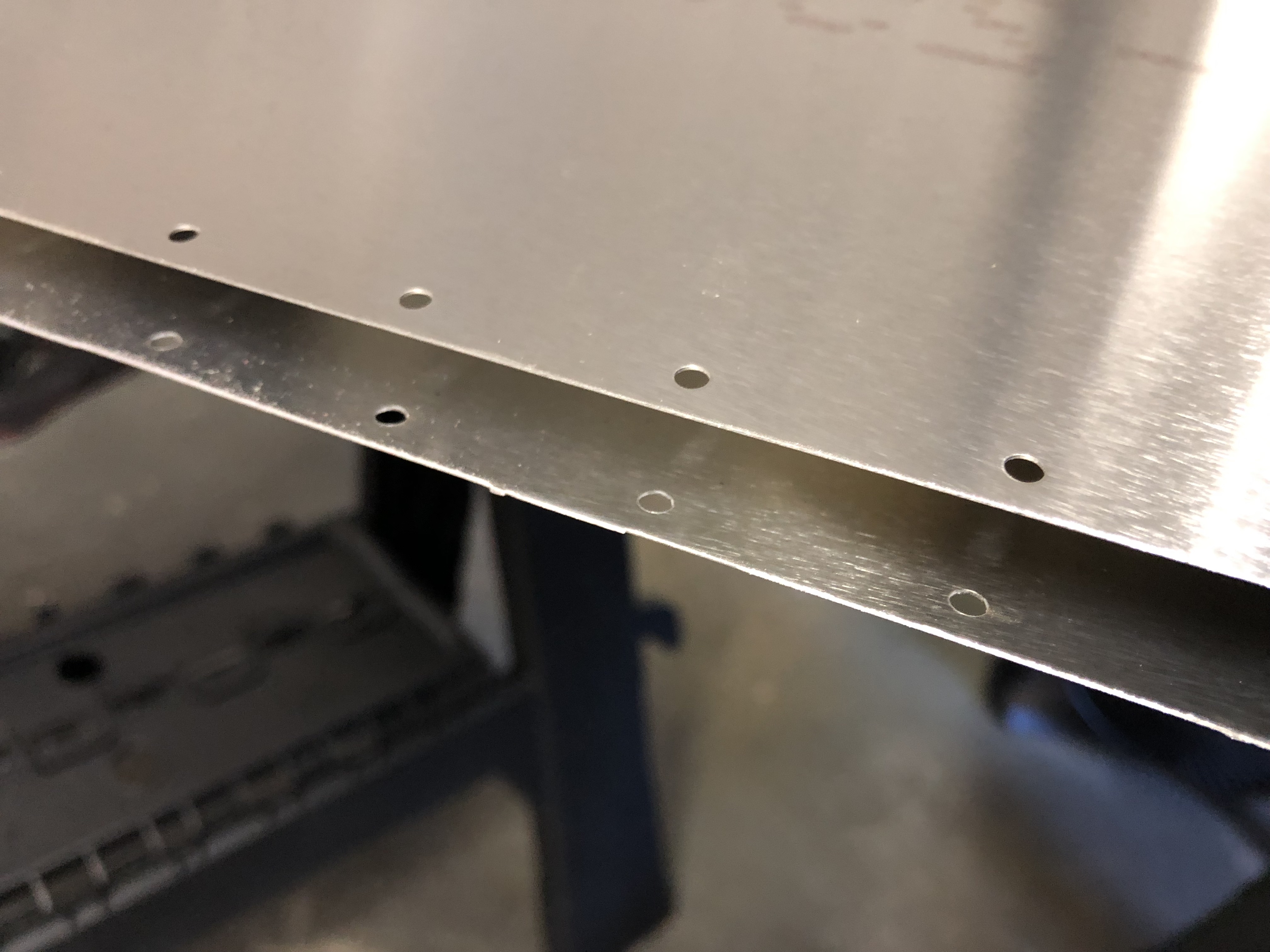
First order of business for the Elevator skin was inspecting all edges and holes and there were a few edges that needed some deburring action.
After deburring everything that needed attention, we wrapped the skins around the rib structure. Since the Elevator is a pretty big part, it was very helpful to have a second pair of hands for this.
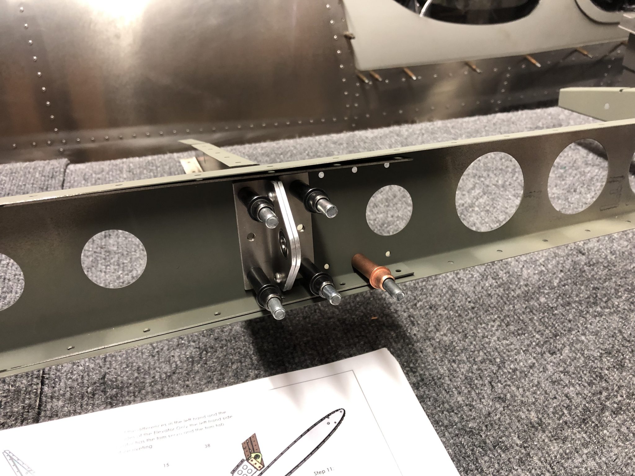
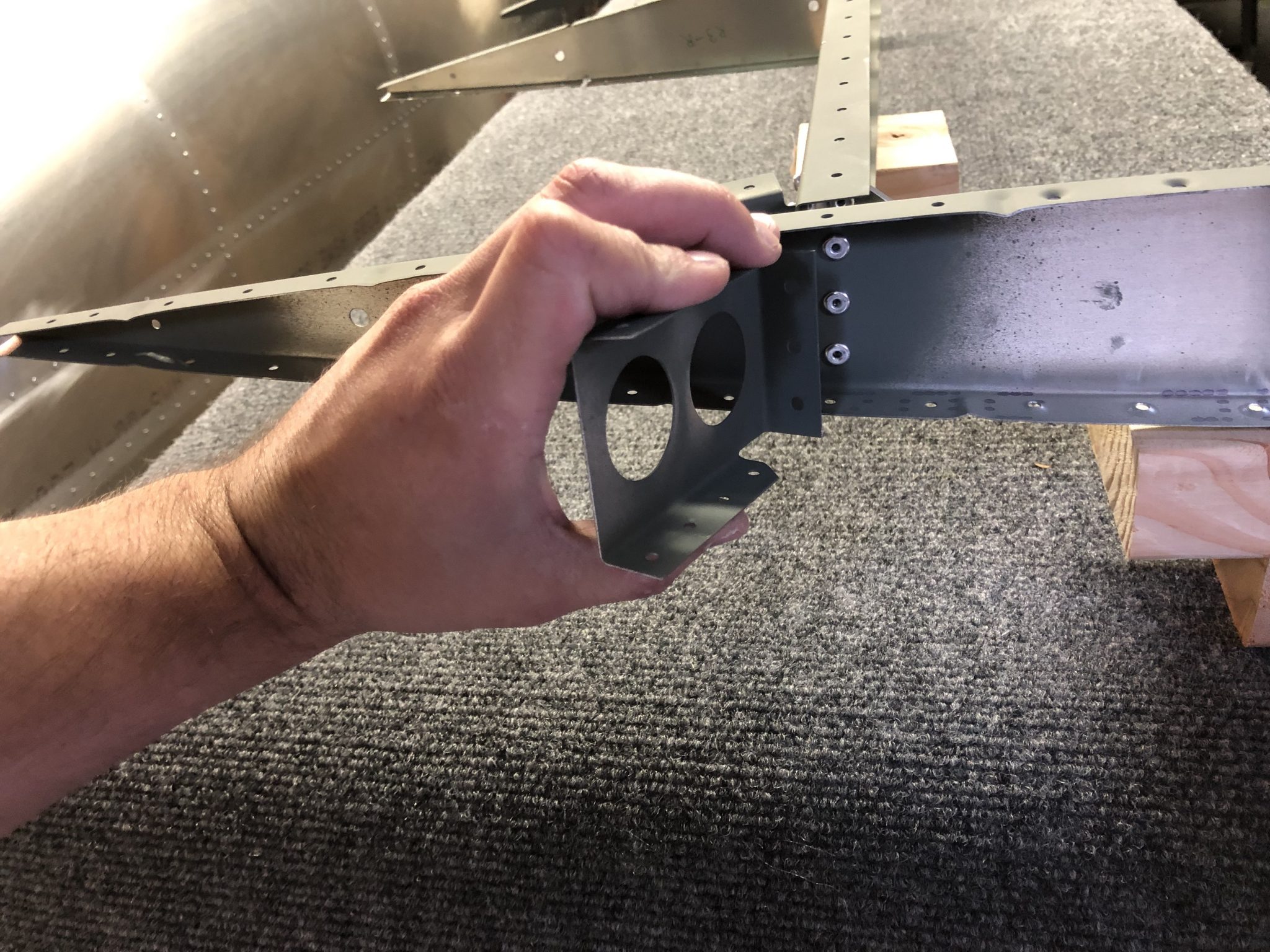
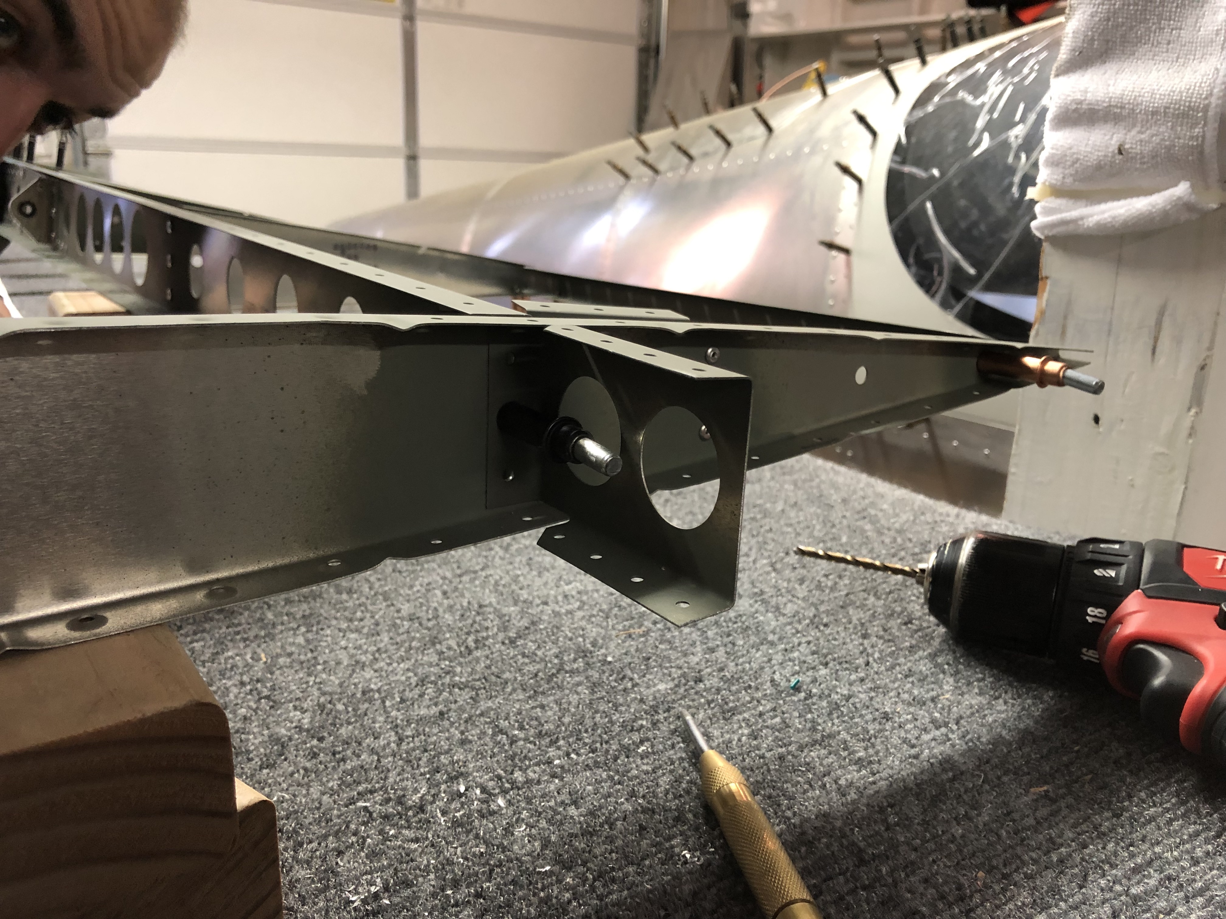
The last thing I had to do before I can start on closing up the skin is to install the backing plate for the Trim motor inspection plate. The plans call for 1/8 rivets, but the holes were actually 3/32, so I had to first up-drill them. There’s also another small error in the plan, in that it says to rivet all 8 holes, but actually only 7 should be riveted, since the top hole is for the screw that holds the inspection plate in place.
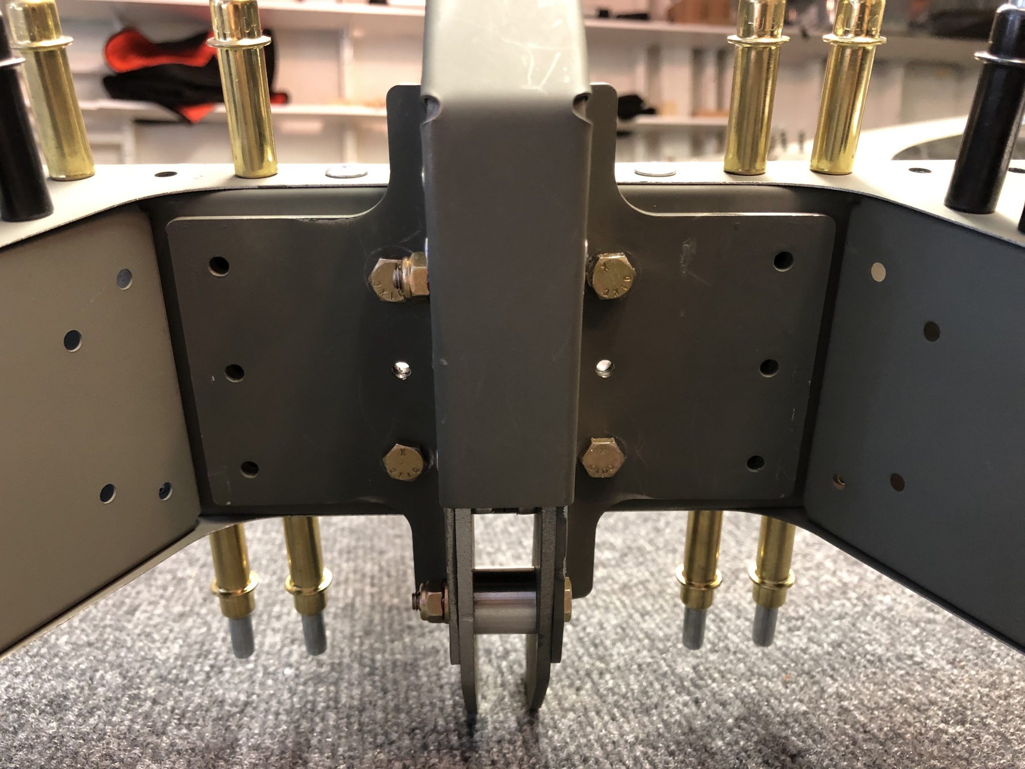
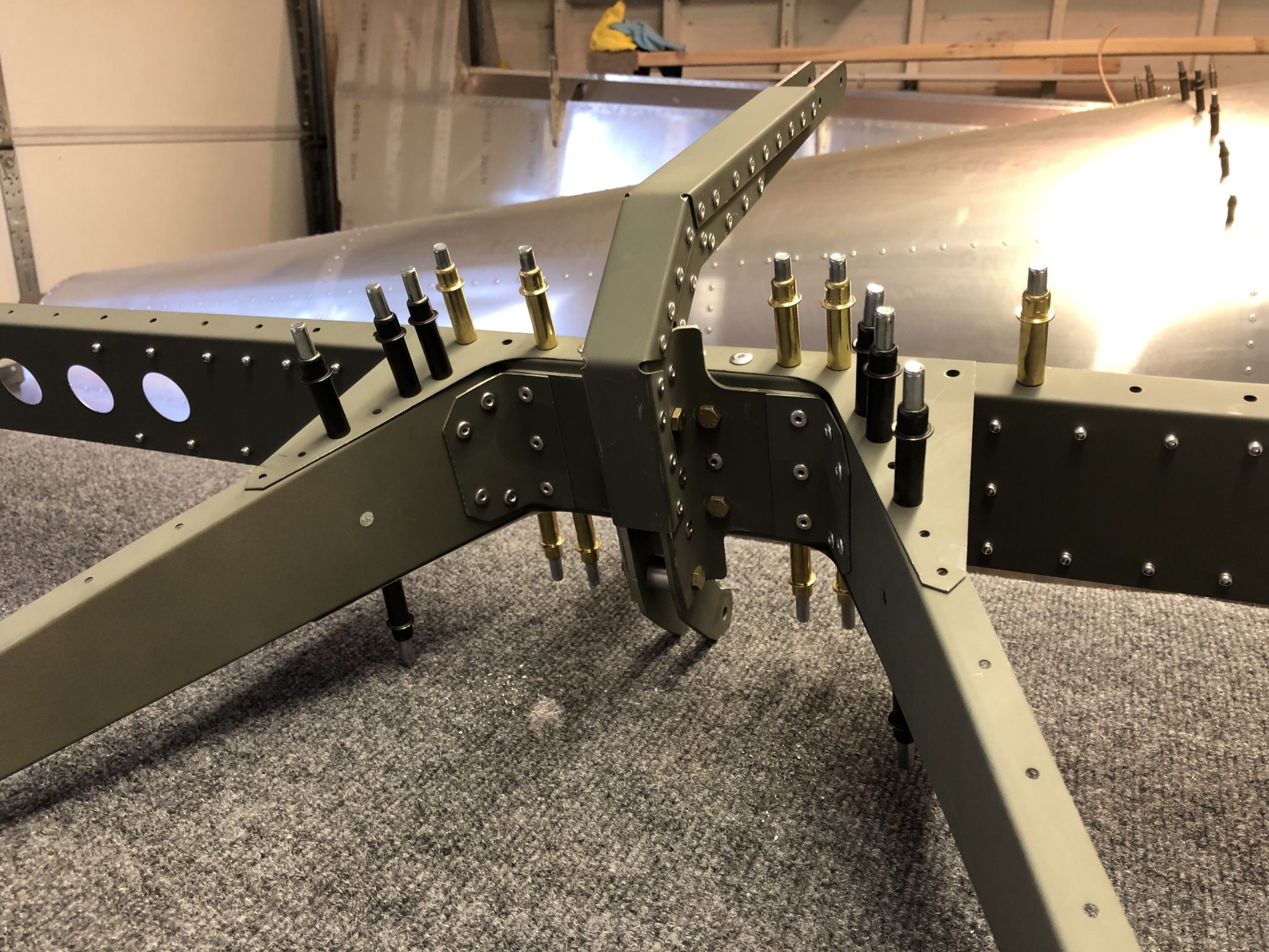
Time to finish off the Empennage and get the Elevator structure going. I received the replacement ribs that are bent just that little bit more in order to properly align with the reinforcement plates and skins and went to work to drill out the bad ribs and put in the replacements.
After that, I went to work and torqued the bolts that connect the control rod and counterweight to the Elevator. There’s also a small support bracket that reinforces the center rib to spar attachment, which is a pretty tight fit, so I had to get out the manual hand riveter.
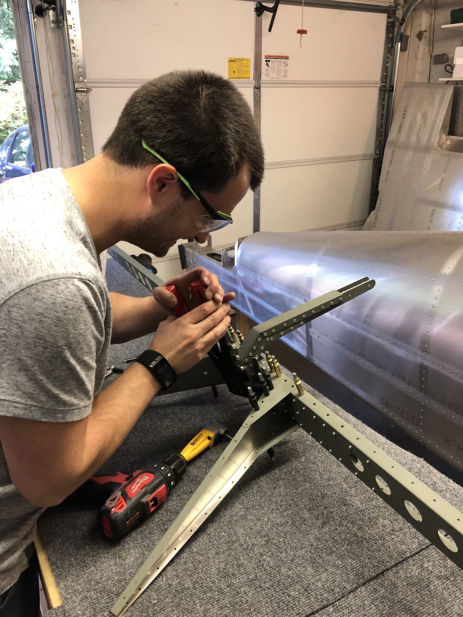
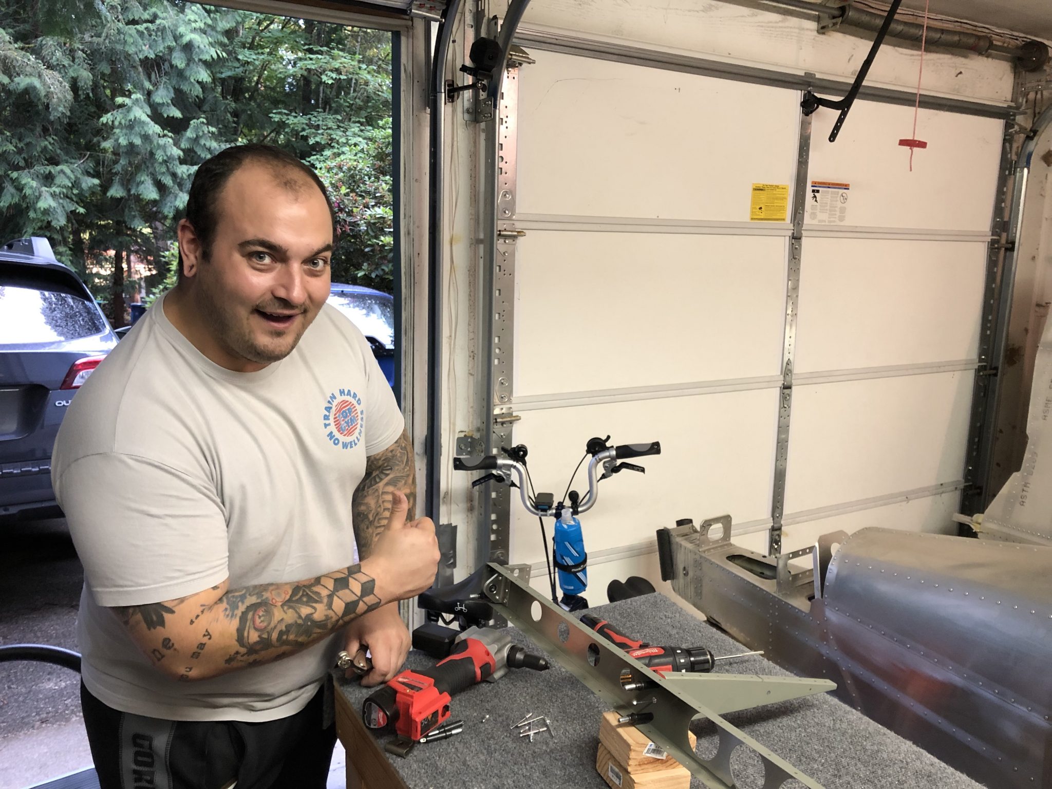
My brother is currently visiting and is enjoying the riveting experience.
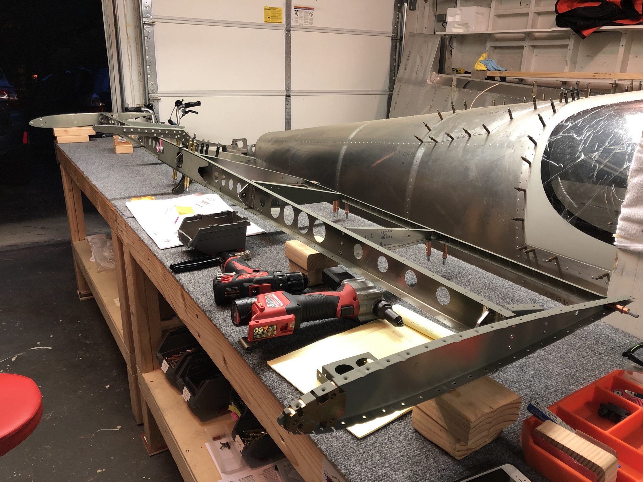
Once the center ribs were finished, we moved on to put the rest of the rib structure in place.
After that I realized there’s a mistake in the plans as they instruct to rivet the edges that hold some of the side counterweights on, but there’s another small end rib that actually has to go on there as I found out after I checked the overall plan for the Elevator. Quickly drilled out the rivets and riveted on the part. A nice trick I learned from another builder for drilling out the rivets without damaging the holes they go through, is to only drill out the top of the rivet (the donut ring) and then use the center punch to push out the back of the rivet. This way you have less chance of enlarging the hole.
With the rib structure in place, time to work on fitting the skin.