Tag Archives: tools

Elevator structure

Hours: 5.25

Time to finish off the Empennage and get the Elevator structure going. I received the replacement ribs that are bent just that little bit more in order to properly align with the reinforcement plates and skins and went to work to drill out the bad ribs and put in the replacements.

New ribs in place and a final picture of a few rivets that people that visited helped pull

After that, I went to work and torqued the bolts that connect the control rod and counterweight to the Elevator. There’s also a small support bracket that reinforces the center rib to spar attachment, which is a pretty tight fit, so I had to get out the manual hand riveter.
Torquing the AN bolts Bolts torqued and support plate riveted

My brother is currently visiting and is enjoying the riveting experience.
My brother enjoying the riveting experience

Once the center ribs were finished, we moved on to put the rest of the rib structure in place.Elevator rib structure finished Clecoing the ribs in place

After that I realized there’s a mistake in the plans as they instruct to rivet the edges that hold some of the side counterweights on, but there’s another small end rib that actually has to go on there as I found out after I checked the overall plan for the Elevator. Quickly drilled out the rivets and riveted on the part. A nice trick I learned from another builder for drilling out the rivets without damaging the holes they go through, is to only drill out the top of the rivet (the donut ring) and then use the center punch to push out the back of the rivet. This way you have less chance of enlarging the hole.
Error in the plan says to just rivet the endcap, but actually this part needs to be riveted onto the side End rib where it should go Holes drilled out and end rib ready to rivet

With the rib structure in place, time to work on fitting the skin.

Finishing the Flaps

Hours: 6

With the ribs for the Flaps out of the way, I am ready to finish the flaps. First order of business is to ensure that I have the ribs all in the right order.
Completed ribs laid out along the right Flap

Once that was figured out, I first clecoed the ribs in place to the bottom of the skins and then closed up the skins and clecoed the top as well.
Ribs clecoed in place to the bottom of the Flaps skin Clecos in place to close up the right Flap

After checking that everything is aligning properly with the skins, I started riveting the skin. The top side is pretty straightforward. For the bottom side, there are a couple of tight spots next to the hinges, so the close quarter rivet wedge came in handy for a couple of the rivets.

Rivets in place Close quarter rivet wedge to rivet the tight space next to the hinge Bottom right side Flap ready to rivet Bottom right side flap almost done riveting

With the right side Flap finished and closed up, I then repeated it all for the left side Flap. There was also a couple of the edges where the hinges sit that needed a bit of deburring attention.
Some deburring was needed for the hole where the hinges go through Upside down view of the left side Flap ribs clecoed in place Almost done with the left side Flap riveting

After I finished the top skins, I did one quick alignment test fit on the wings and everything looked good, so then I finished up both sides by riveting the front rivet lane that closes the skin against the other side.
Front line ready to close up the skins of the Flaps for good Almost done riveting the Flaps Completed left Flap Both Flaps completed

Final alignment check

Once I finished all the riveting, I did one final test fit onto the wings. I used a bit of mason string and my laser level and everything is looking good. Now onto finishing the Elevator.
Final test fitting and alignment checks Final test fitting and alignment checks

Timelapse of building the Flaps

Vertical Stabilizer skin riveting

Hours: 3.5

With the wiring finished and the Antenna fitting done, I am now finally able to close up the Vertical Stabilizer and rivet the skin.

To begin, I closed up the left side of the skin and held it in place with clecos, since this is the side where the Antenna slides through the enlarged rivet hole, while on the right side I had to create the custom notch so that I can pull the skin around the Antenna.
Left side of the Vertical Stabilizer closed up with clecos

Once that was done, I riveted on the support plate for the Antenna onto the top rib of the Vertical Stabilizer.
Riveting the Antenna support plate in place Antenna support plate riveted in place 

Now that the structure is complete, time to mount the Antenna permanently in place. Using two 20mm long M4 screws, washers and Nyloc nuts and some medium strength threadlocker I mounted the Antenna in place. Here’s the Antenna mounted in place and the wire connected to the Antenna using the BNC connector I crimped onto the wire. Antenna ready to be mounted Antenna mounted and wire connected

Riveting the skin

With all the prep work finished, I closed up the right side of the skin, made sure everything fits correctly and clecoed it in place. There are two holes on the bottom on each side that are not riveted, but instead I have to install Rivnuts in them, so I marked out those holes, so I don’t accidentally rivet them.
Vertical Stabilizer skin closed up and ready for riveting Holes where I have to install Rivnuts marked

There were two rivets that I had to shorten in order for them to fit flush near the Antenna. So I made a small template for the dept through a piece of wood and then shortened them accordingly.
Wood piece to hold the rivet in place to shorten Rivets shortened (and normal length on the left for reference)

After that, it was just a matter of pulling the many rivets on both sides of the skin to close the Vertical Stabilizer up for good.
Riveting the right side in progress Riveting the left side in progress Riveting the left side in progress Done riveting the skins of the Vertical Stabilizer

The last part was to install the two rivnuts on the bottom on each side, so after enlarging the holes using my step drill and reaming them out using my hand reamer, I got out my rivnut puller and high strength loctite and put those in place.
Holes enlarged for the rivnuts Rivnuts installed

With the Vertical Stabilizer completed, I then did a quick test fit and mounted it on top of the Fuselage and also attached the Rudder for a moment – almost looks like an airplane.Completed Vertical Stabilizer  Quick test fit of the Vertical Stabilizer and Rudder

Timelapse of building the Vertical Stabilizer

Technical Counselor visit & Vertical Stabilizer Antenna wiring

Hours: 5

This morning I had my first visit from my local EAA Chapter 84’s Technical Counselor to look over my build and give me some advice as part of EAA’s Technical Counselor program.

This was the first Sling kit for him and he was impressed by the quality of the kit, its completeness and the instruction plans. We looked over my completed parts of the Empennage and talked about wiring, avionics and things to look out for. He also gave me some good general advice and stressed the point of documenting, particularly around wiring, since many years down the line there’s nothing worse than finding a wire and not knowing what it is for exactly, so he was happy to see my label maker and my active use of it.

We filled out the visit report and agreed to meet again after I’m further into the build and working on the interior of the Fuselage.

Vertical Stabilizer wiring

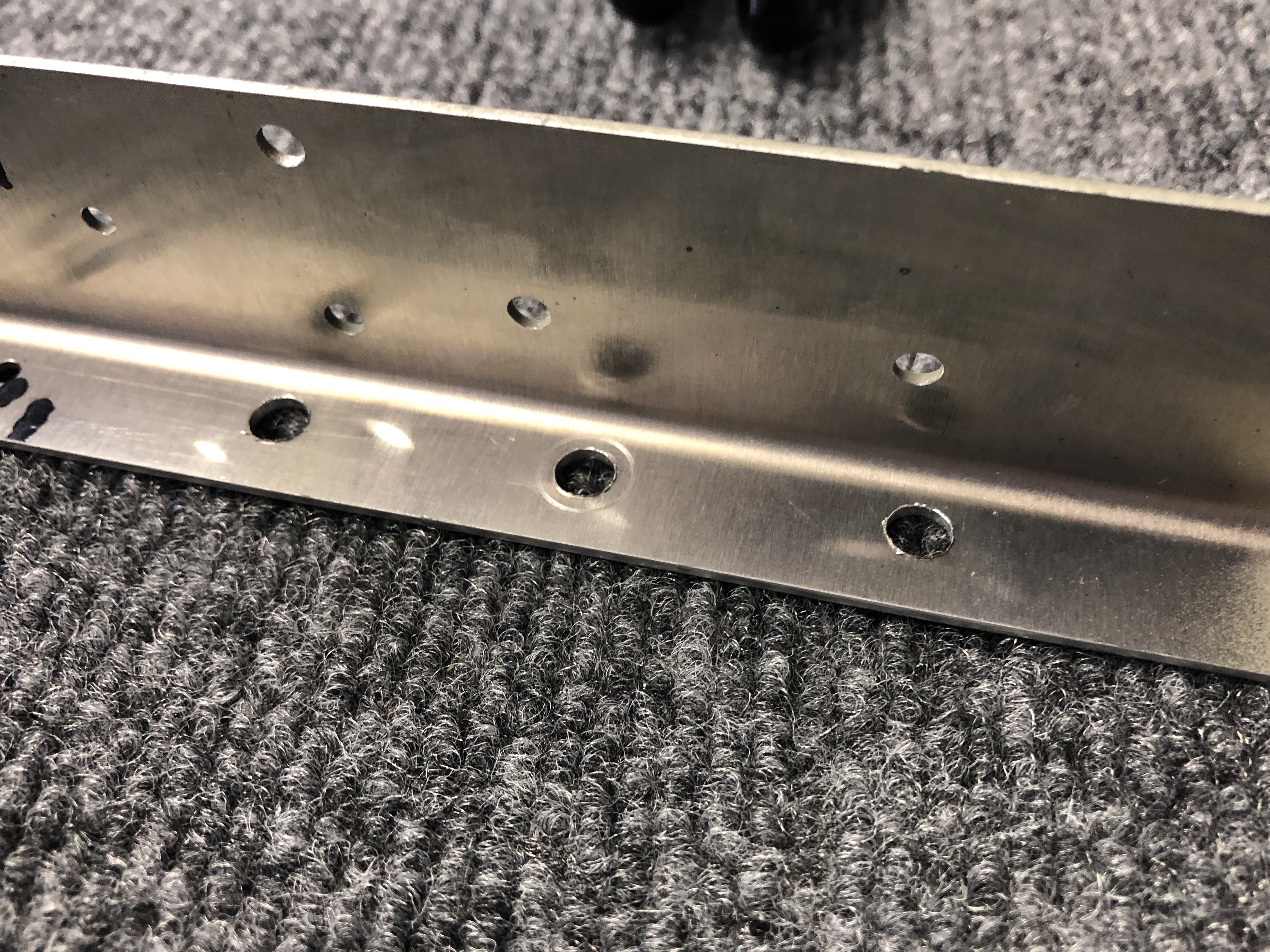
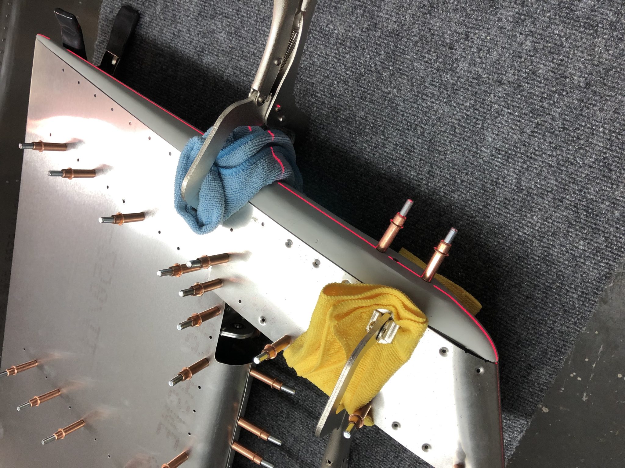
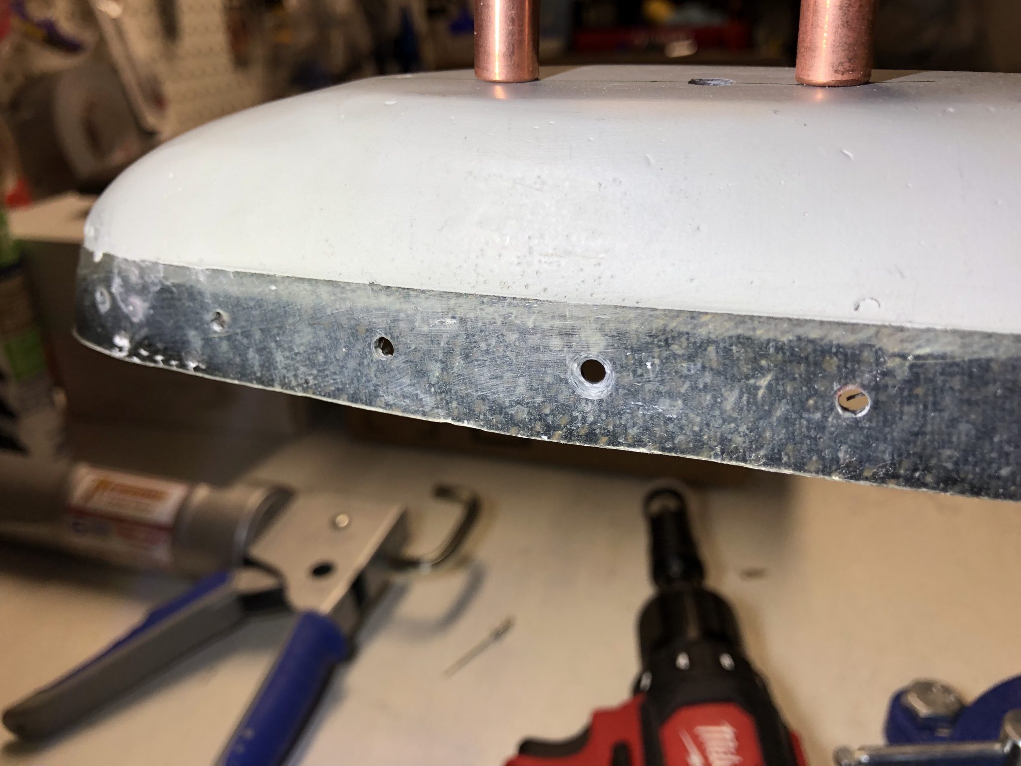
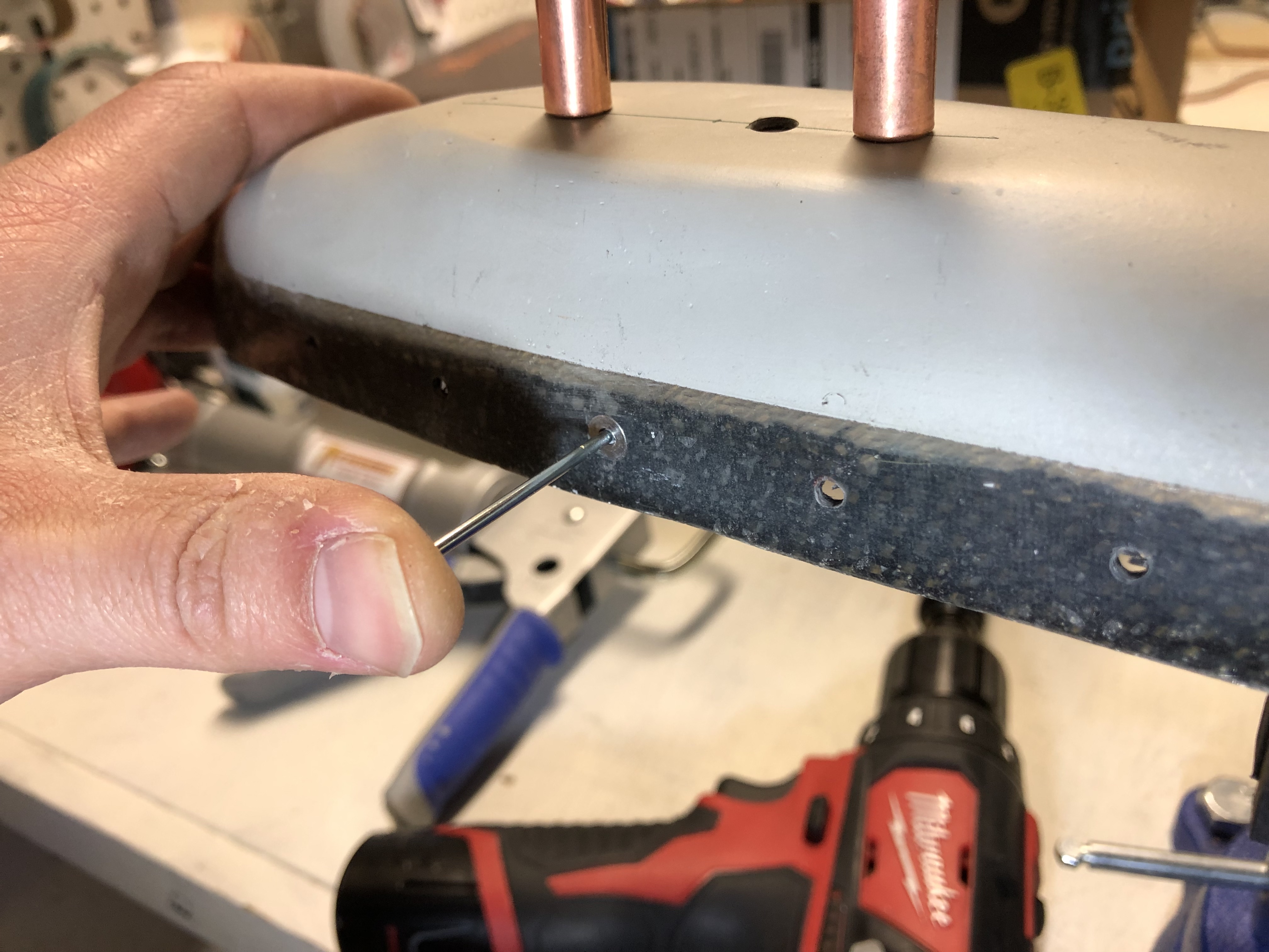
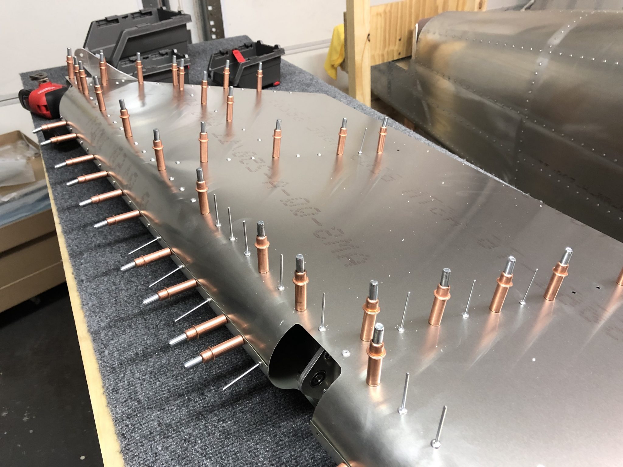
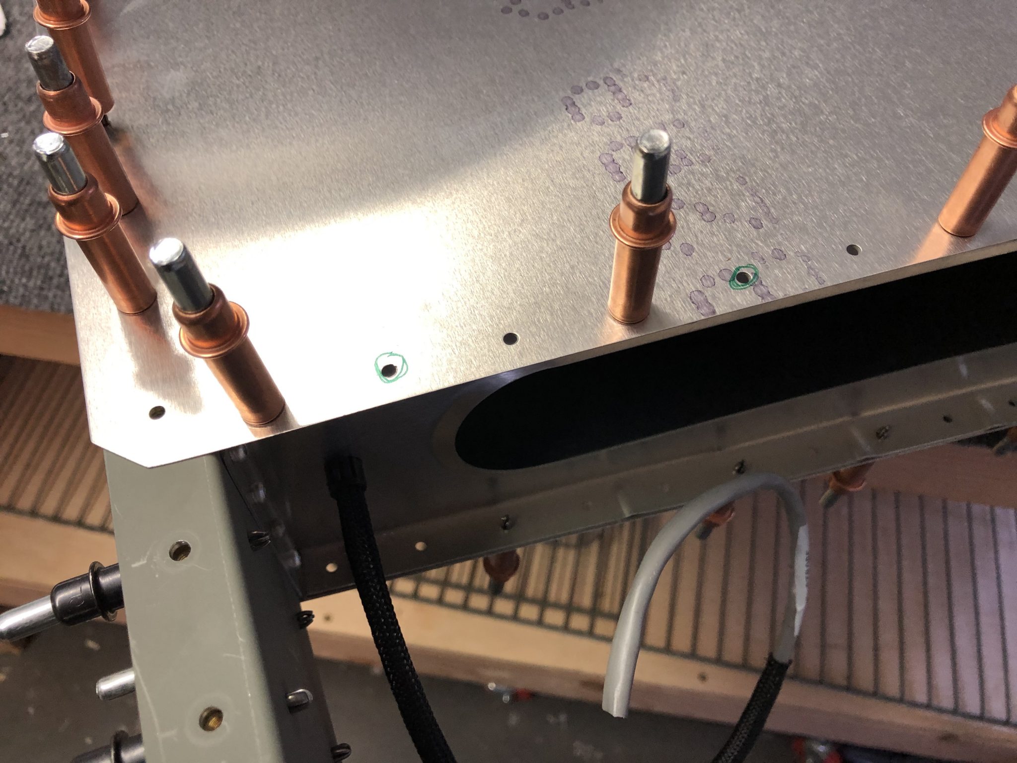
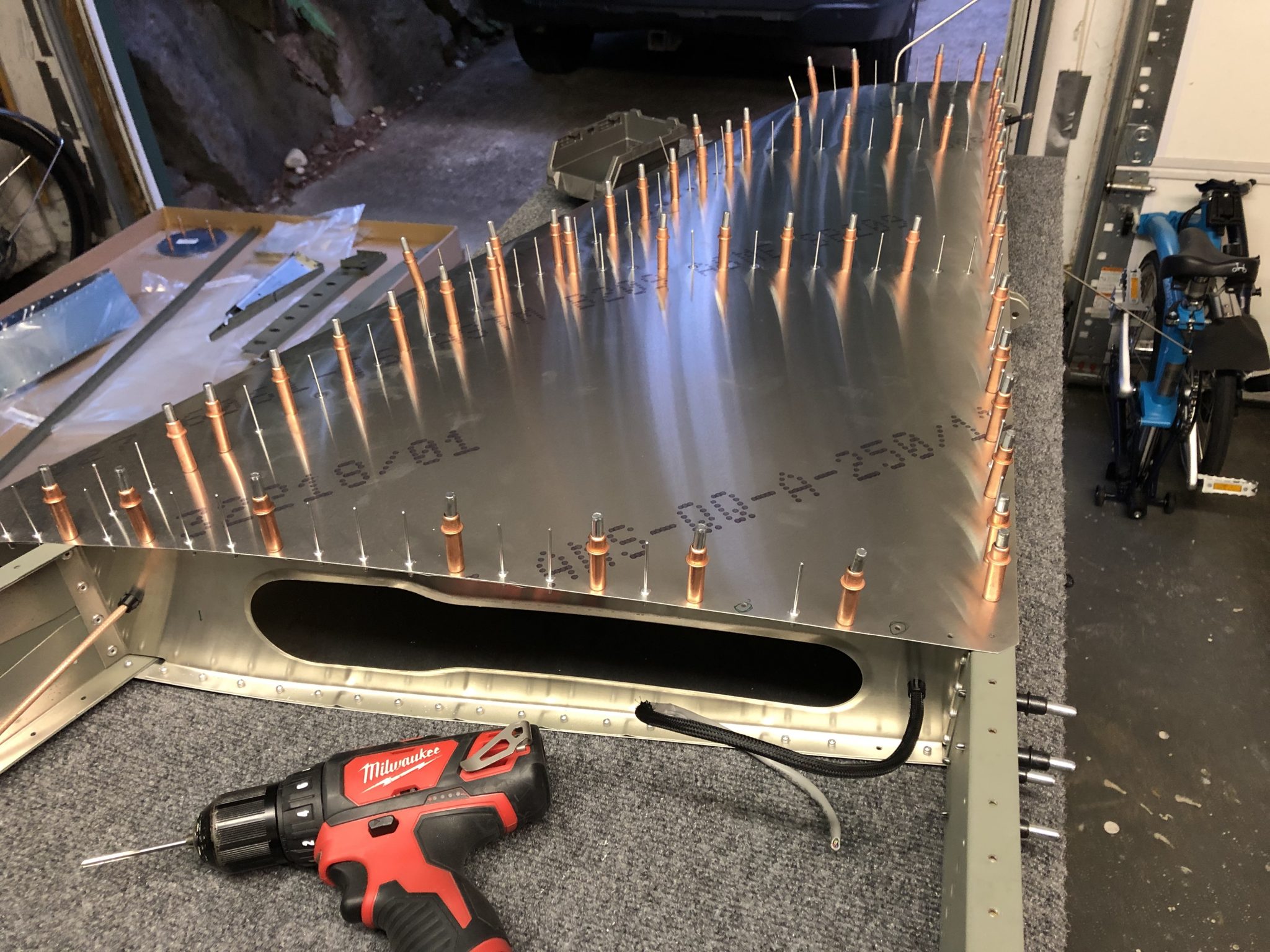
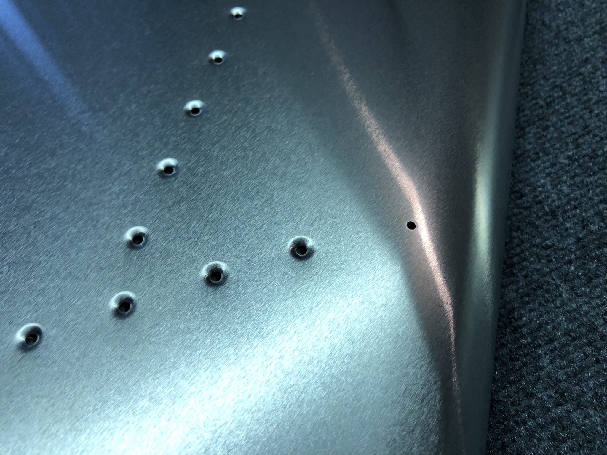
Now, back to building. As I finished the match drilling of the dimpled holes the other day, I had to dimple the hole that was missing a dimple, so I got out my modified hand dimpling tool and quickly did that dimple.

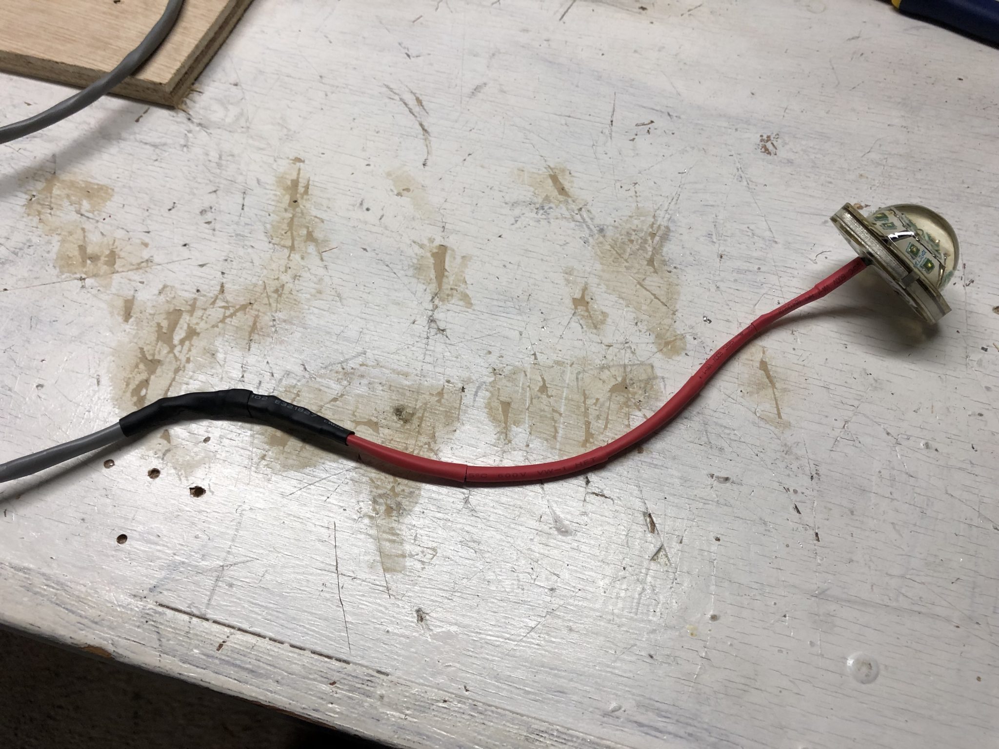
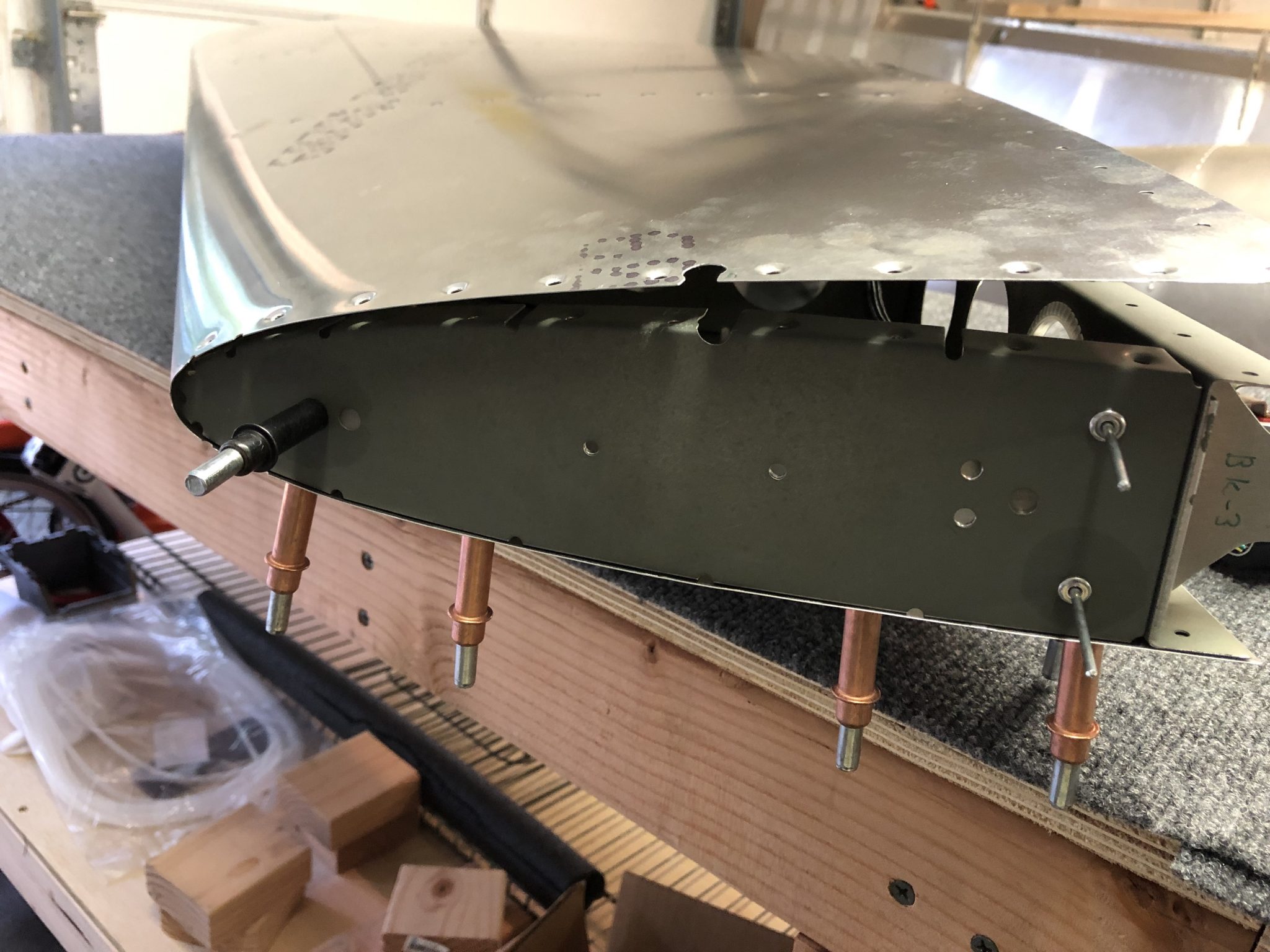
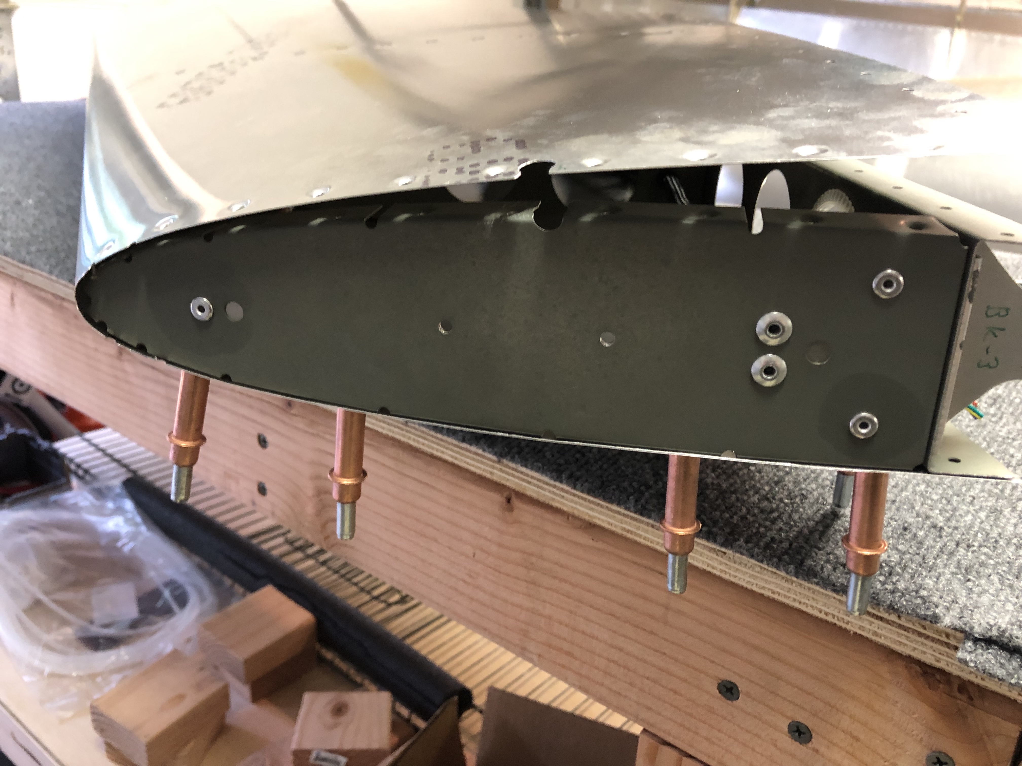
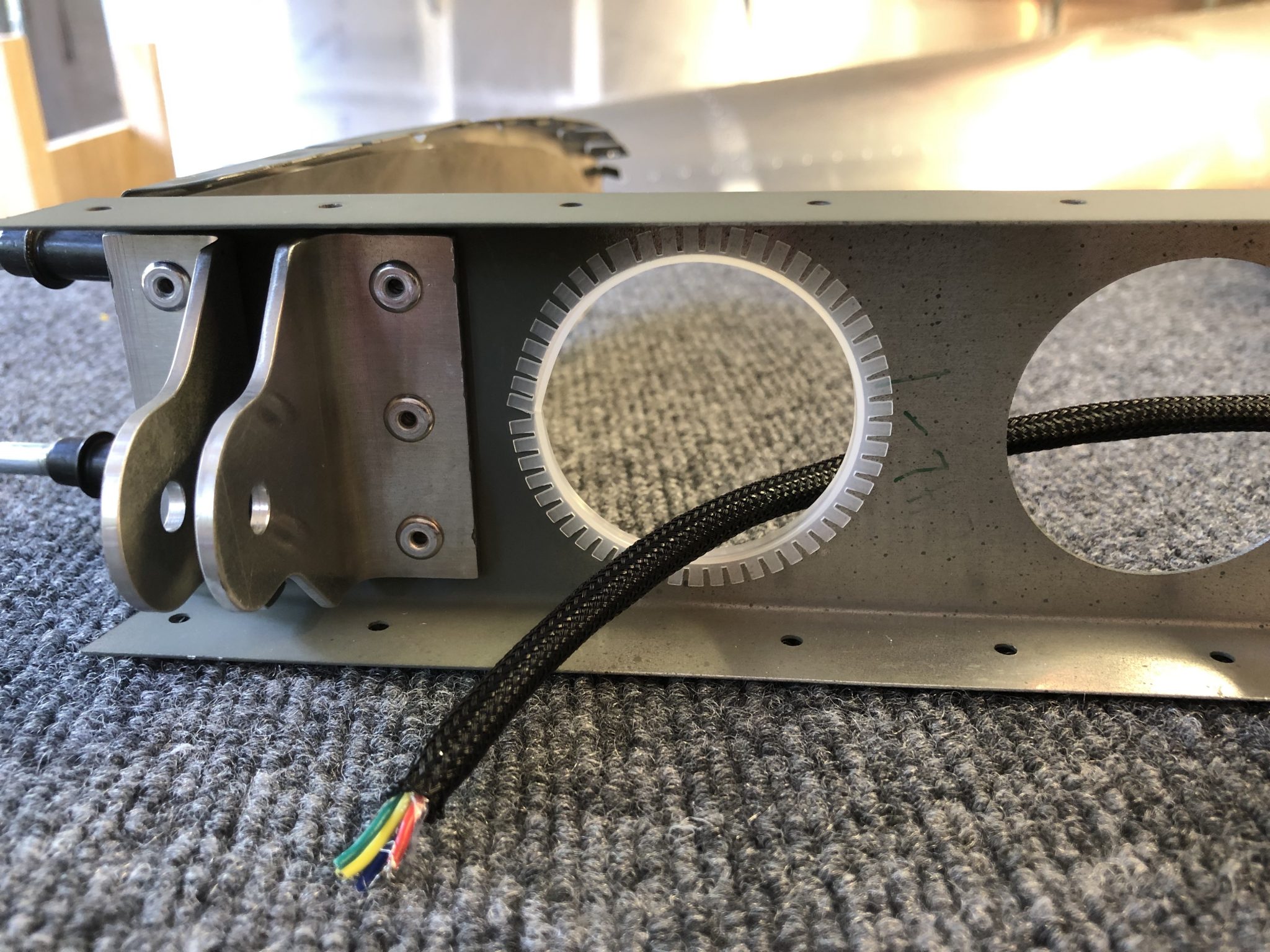
After that I worked on finishing the wiring the run through the Vertical Stabilizer for both the Anti-collision light on the Rudder, as well as the NAV Antenna.

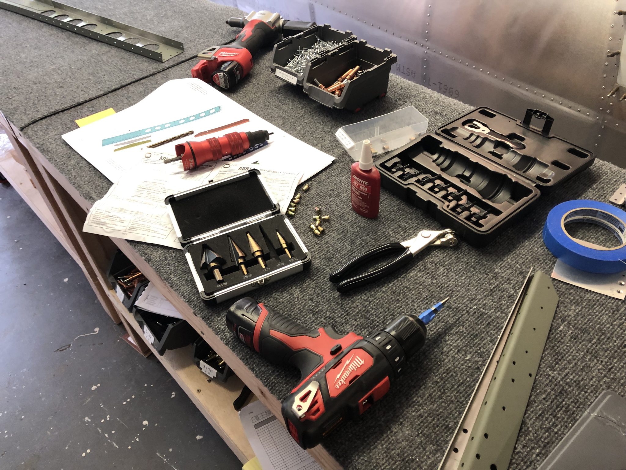
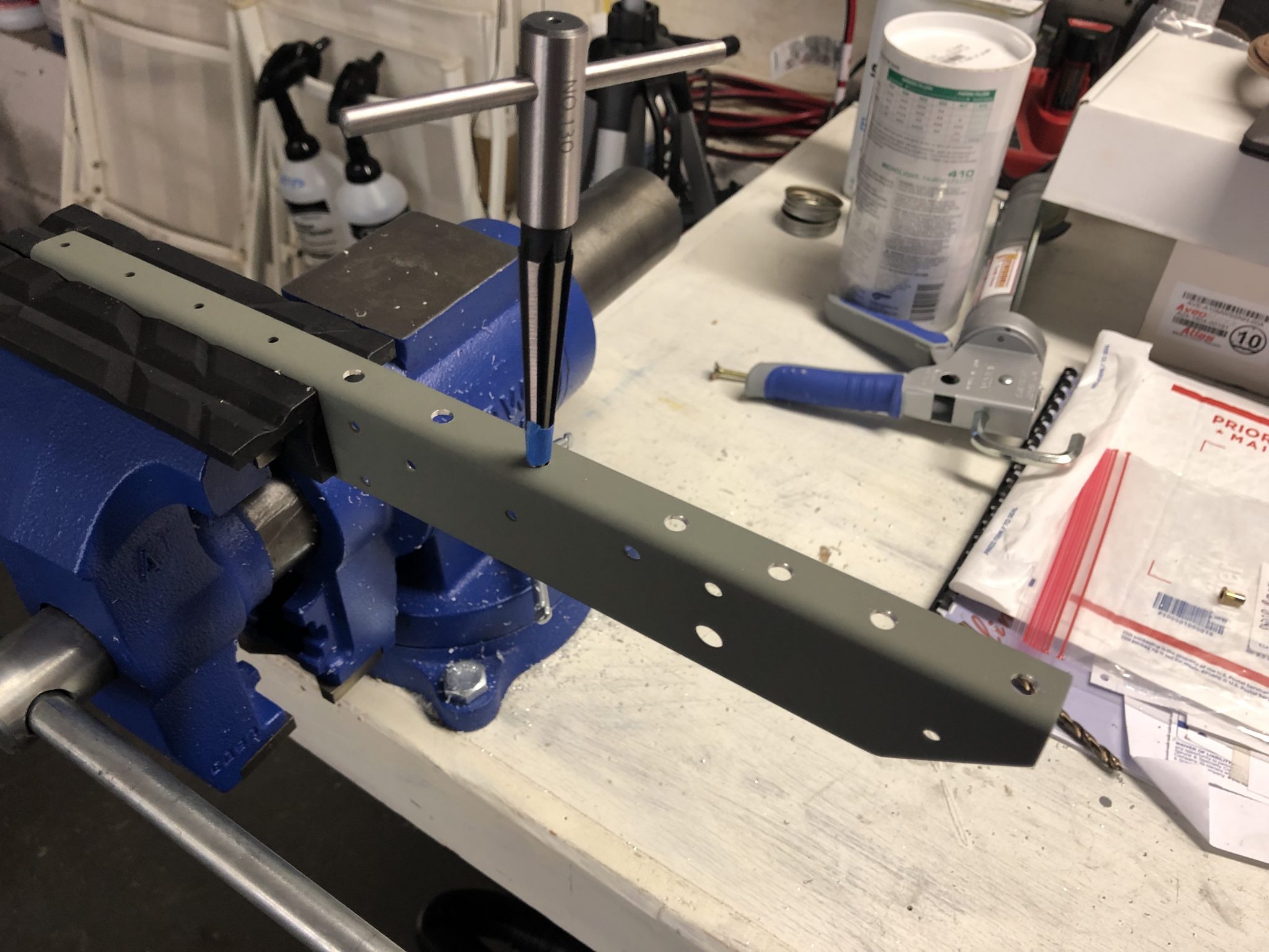
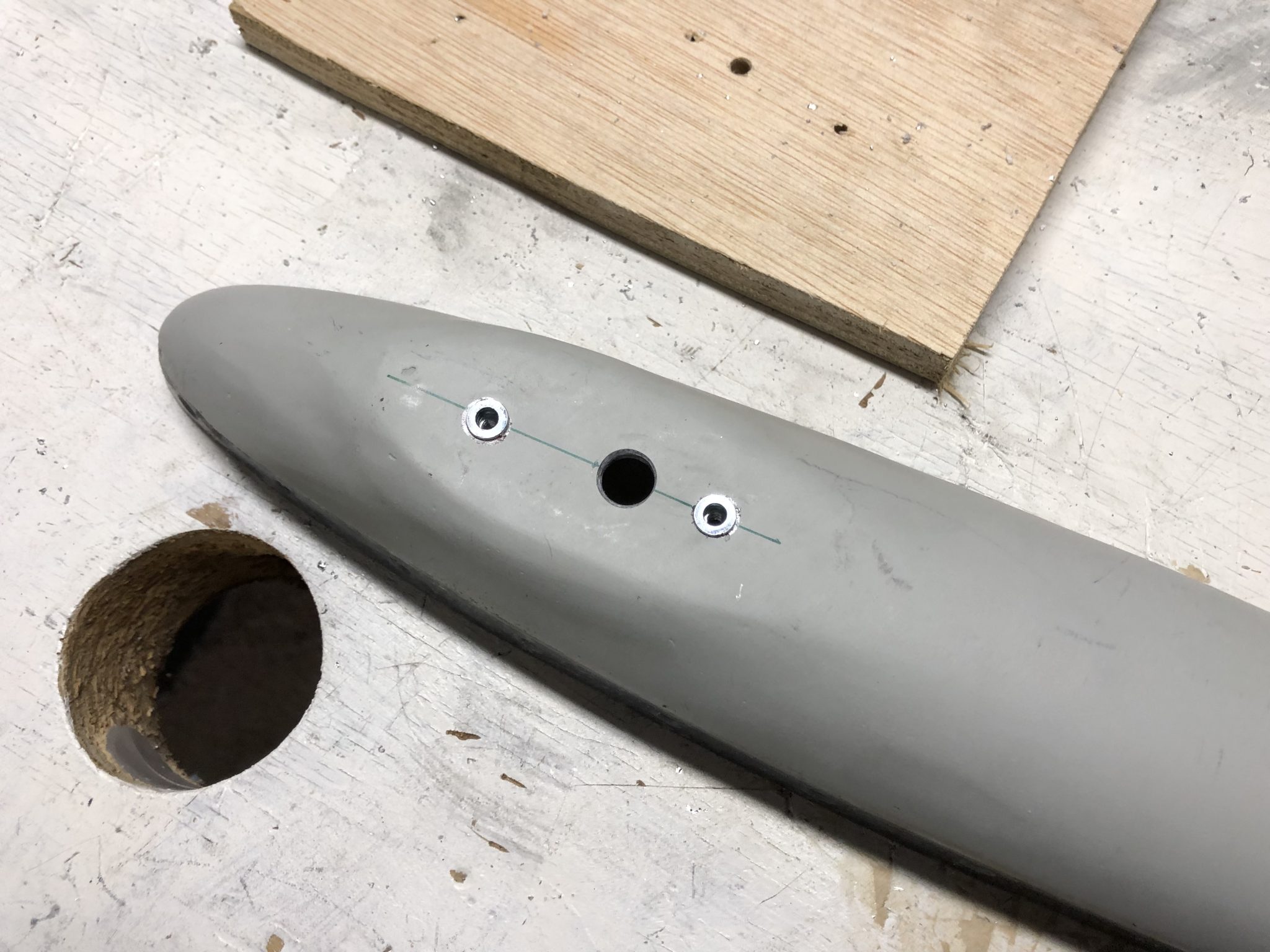
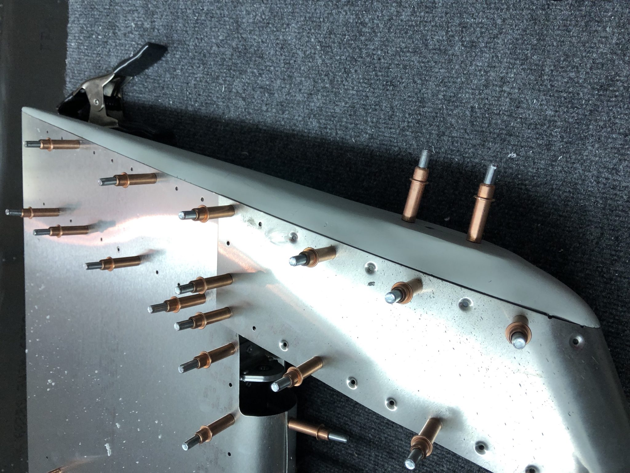
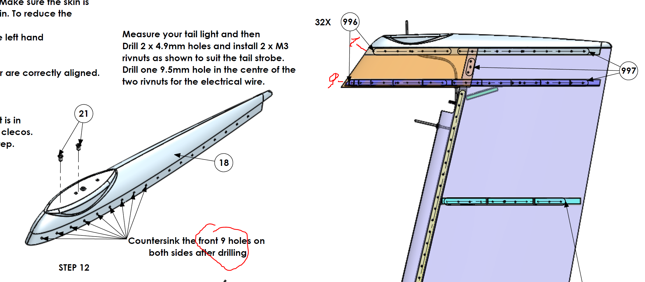
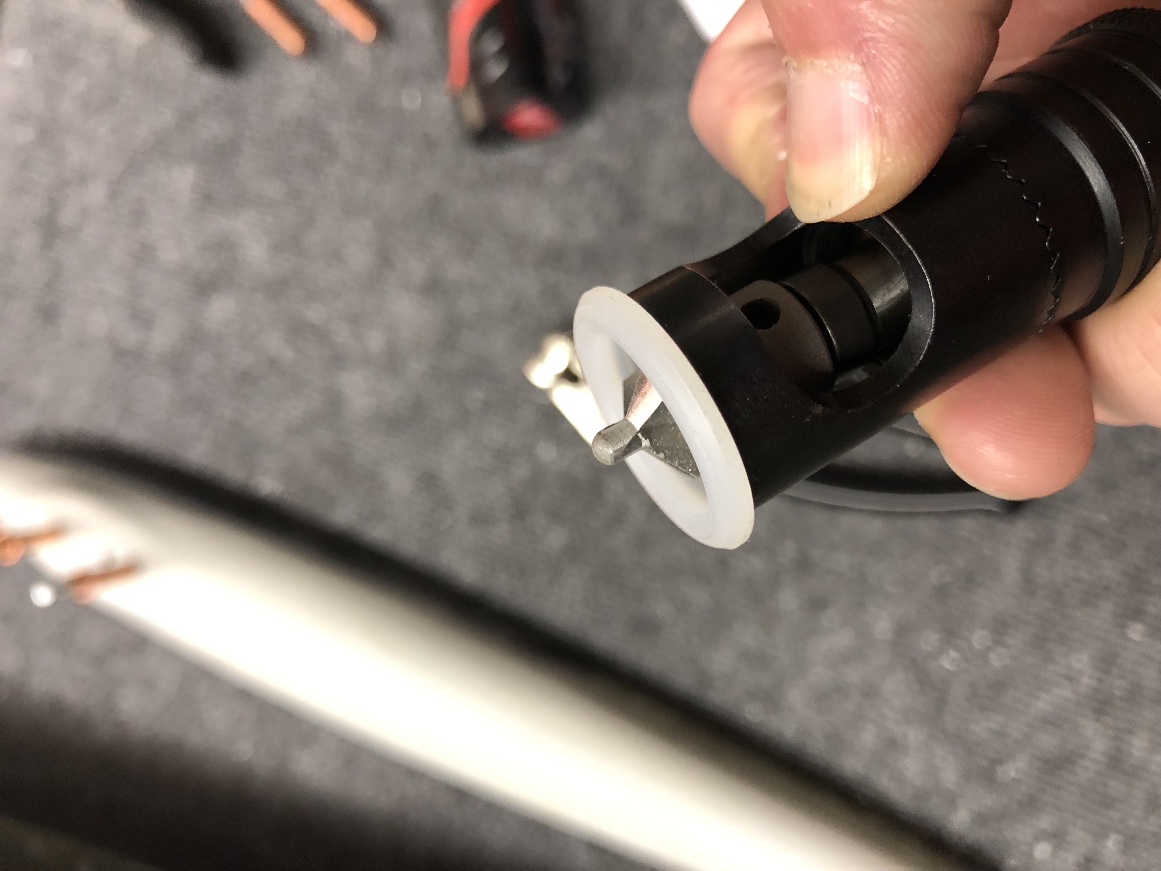
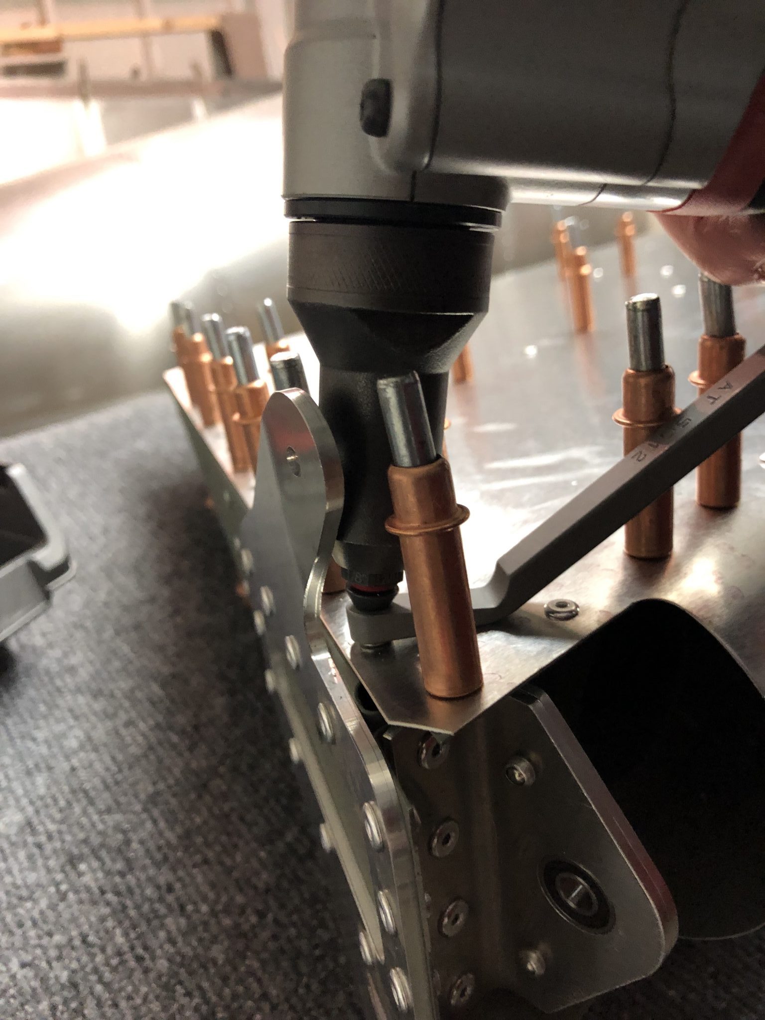
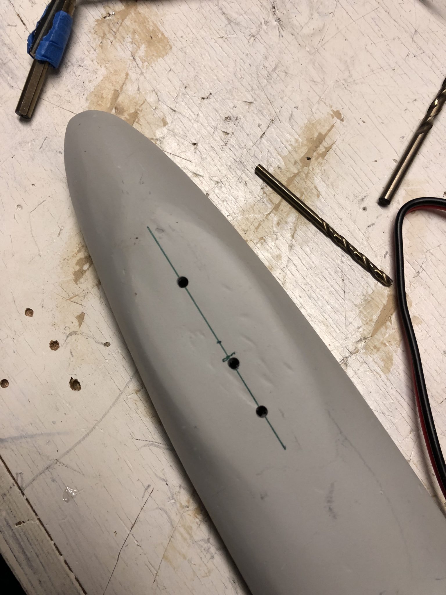
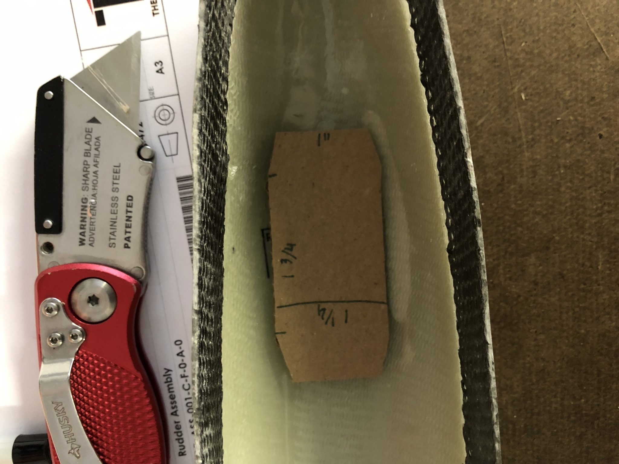
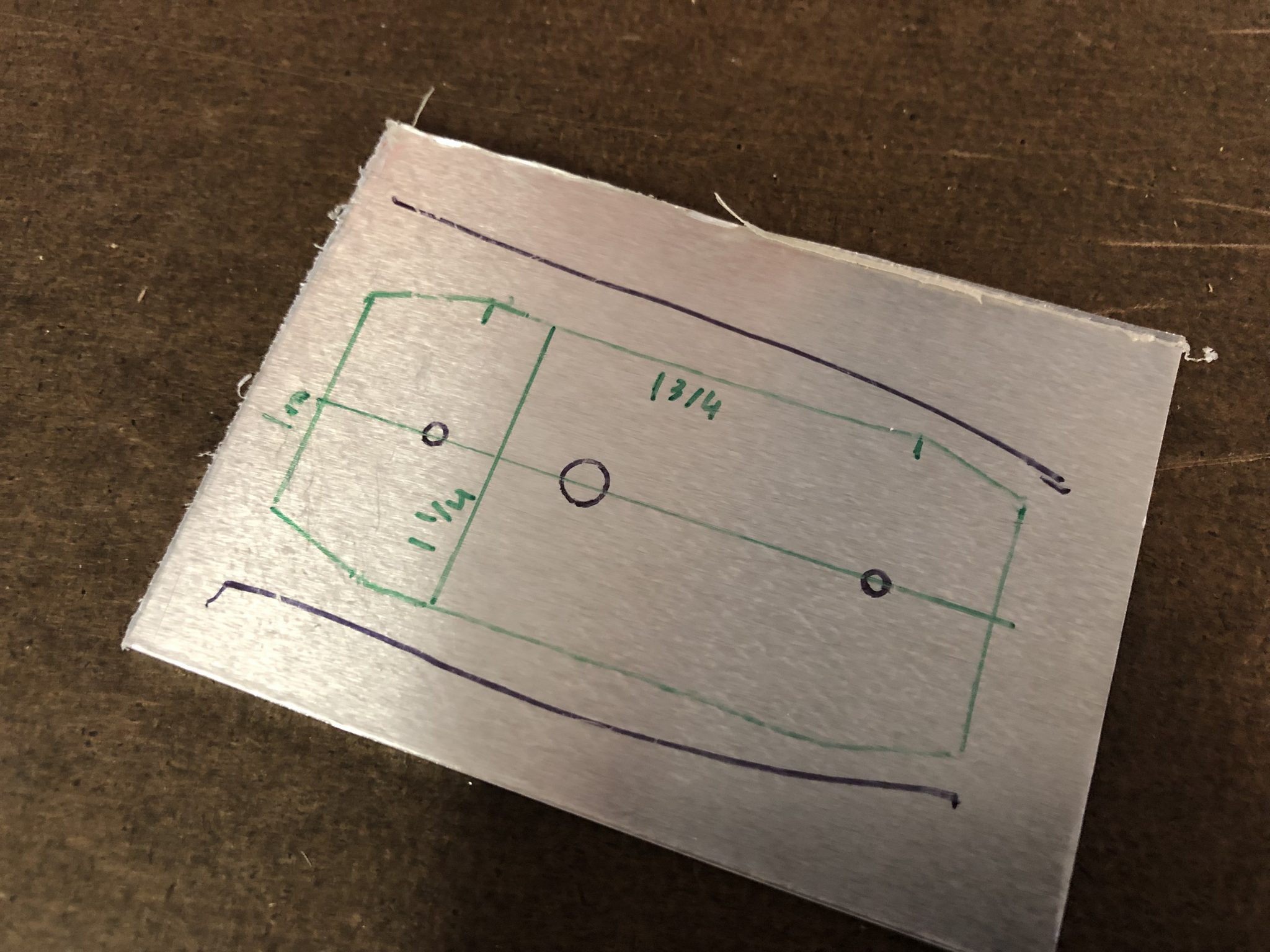
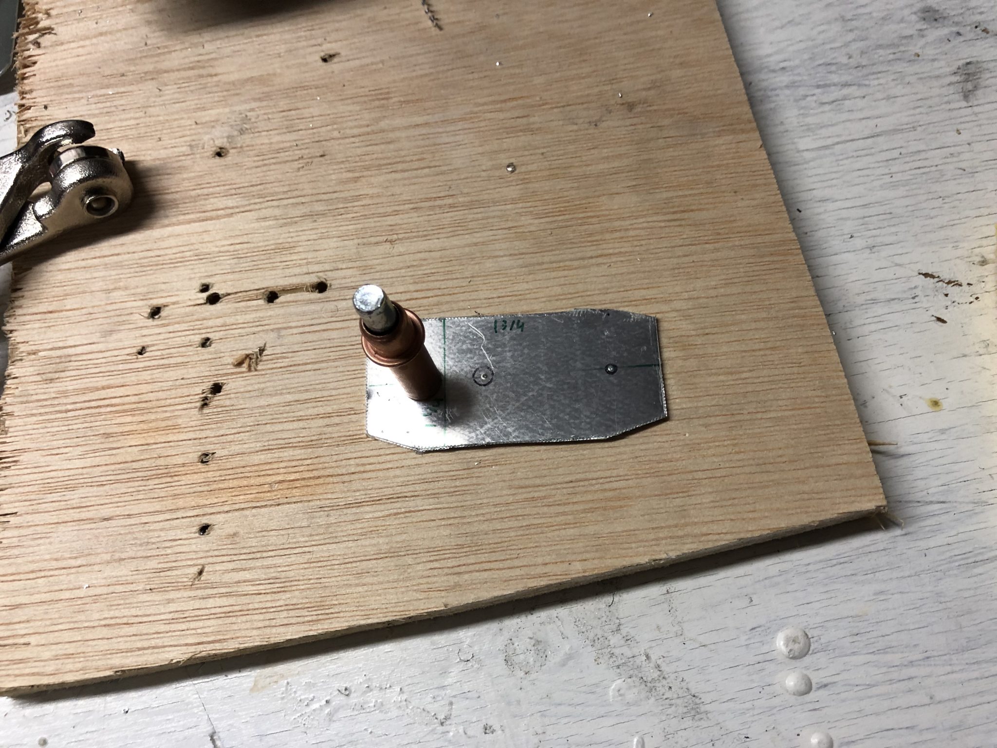
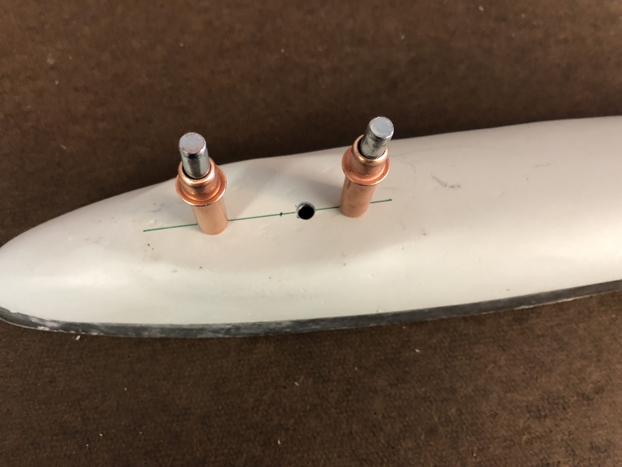
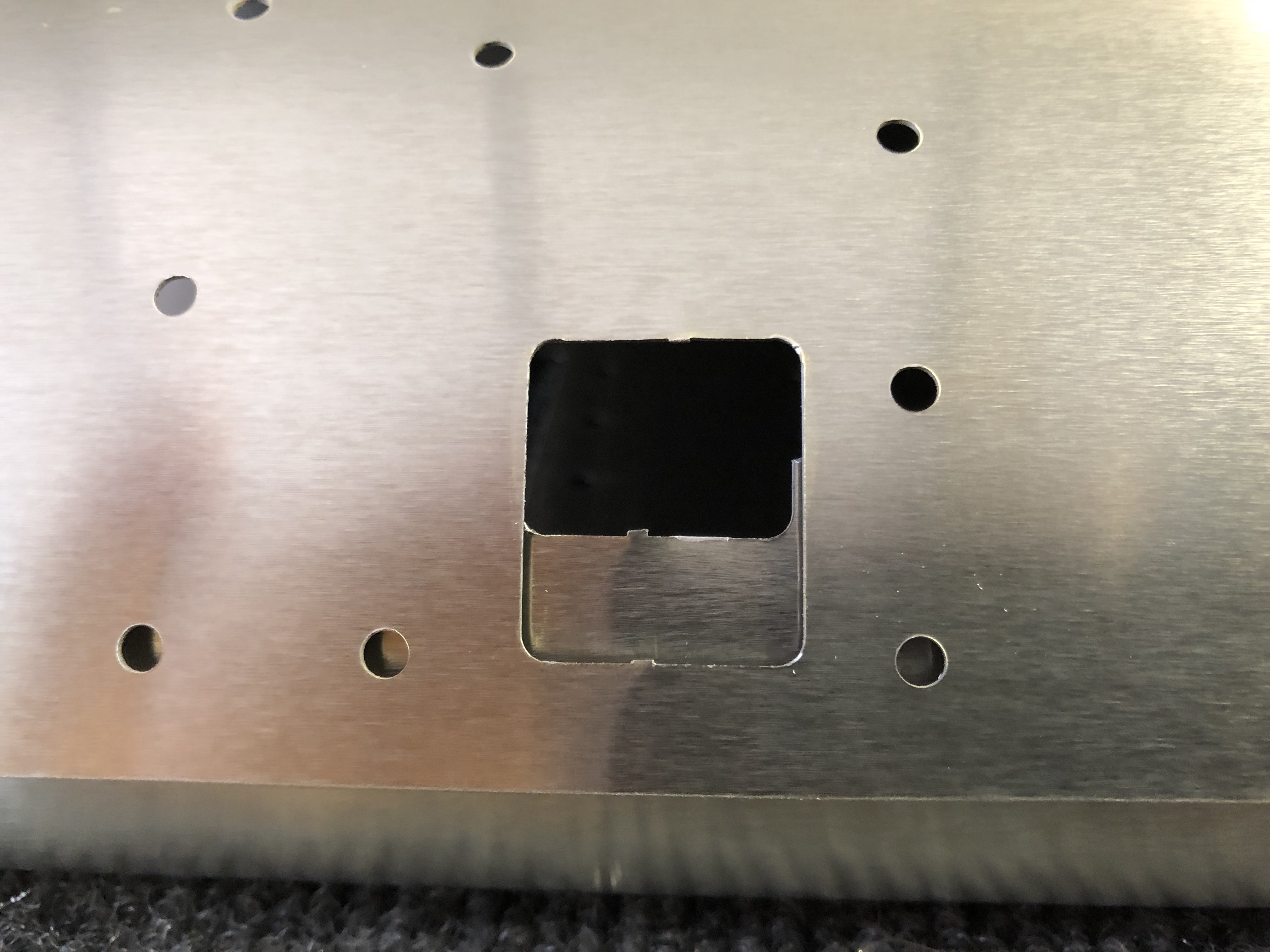
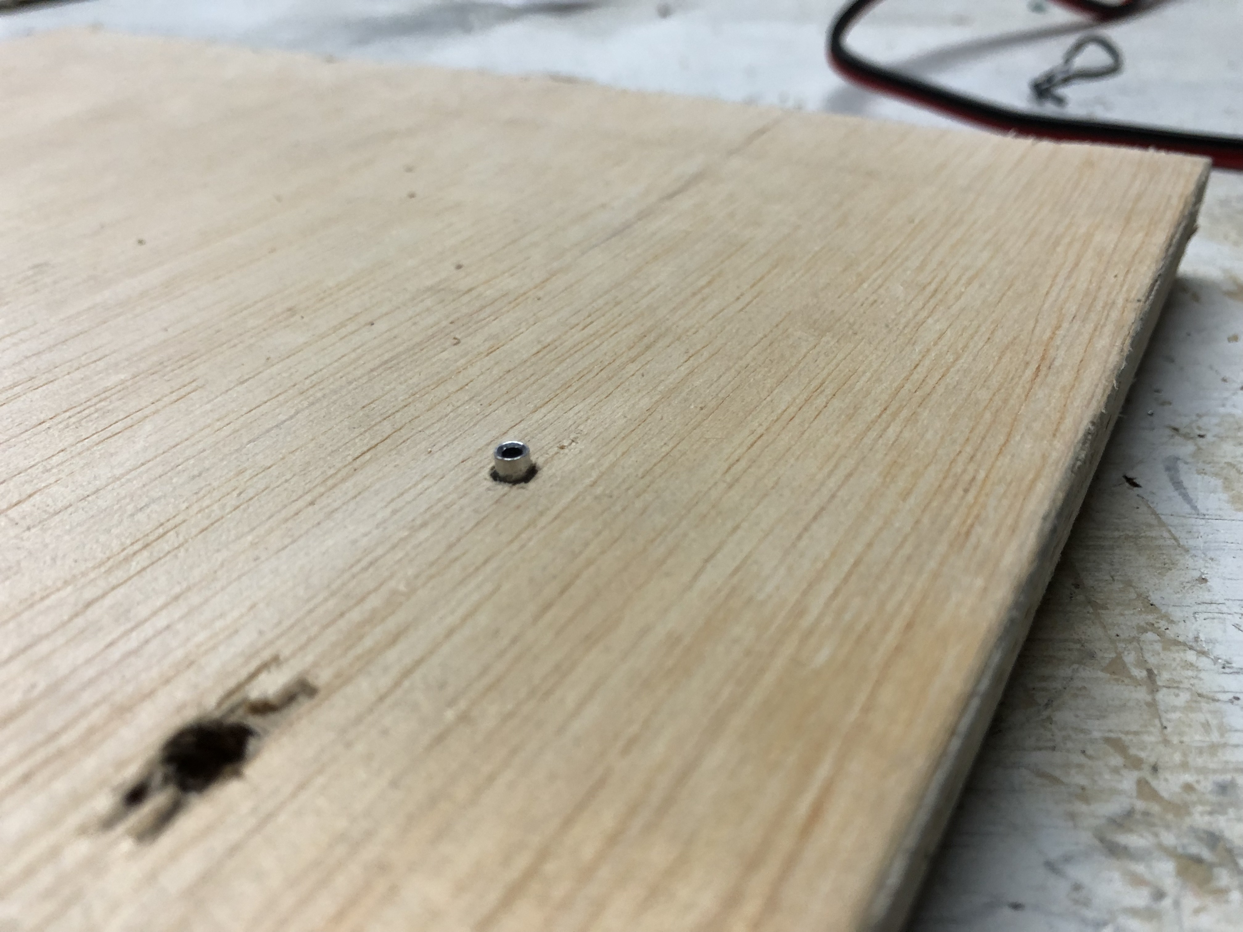
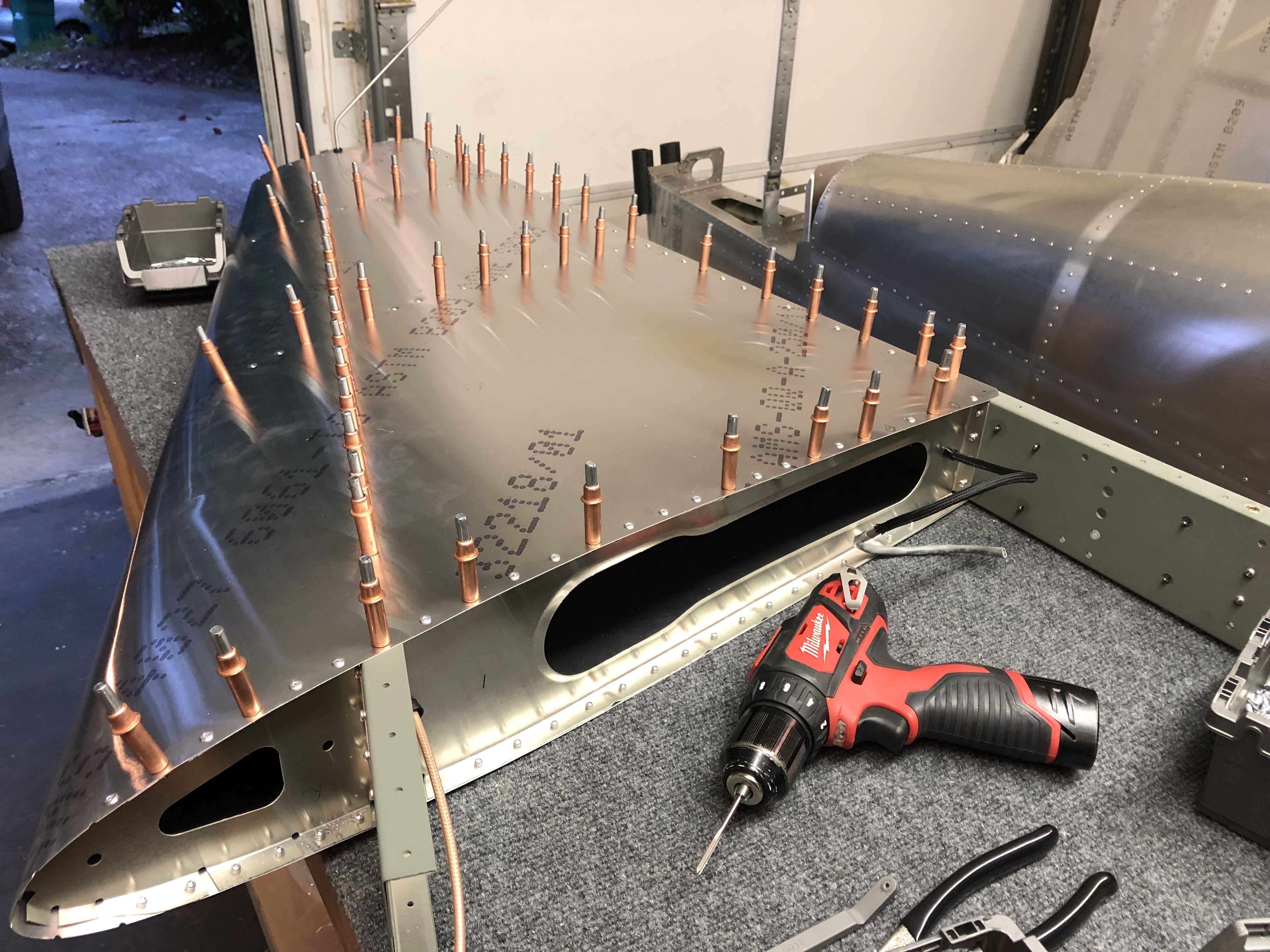
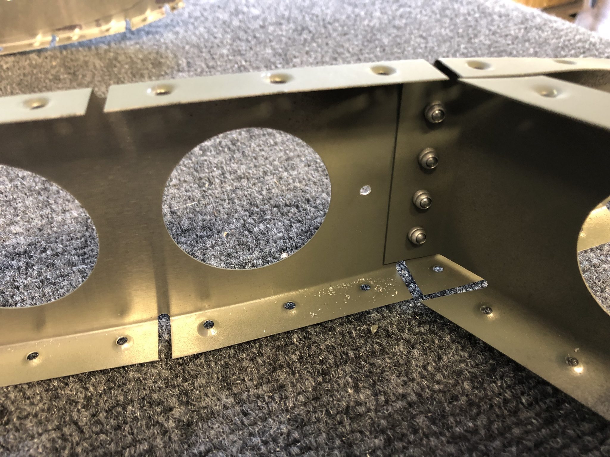
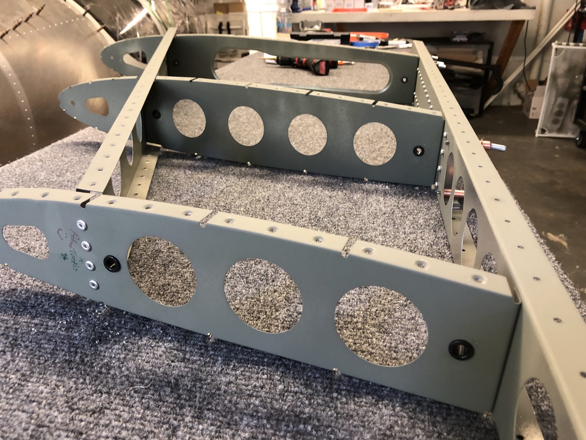
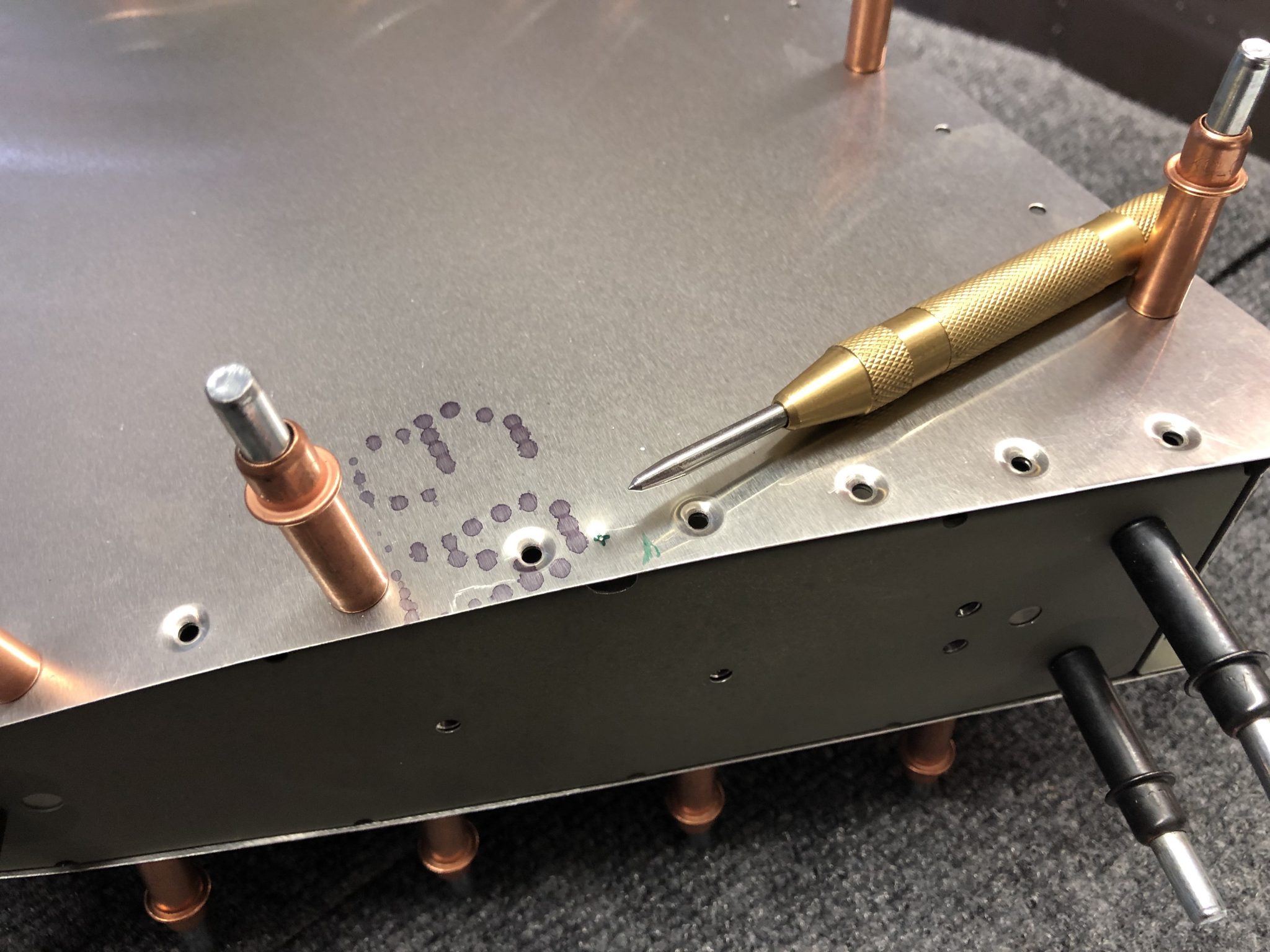
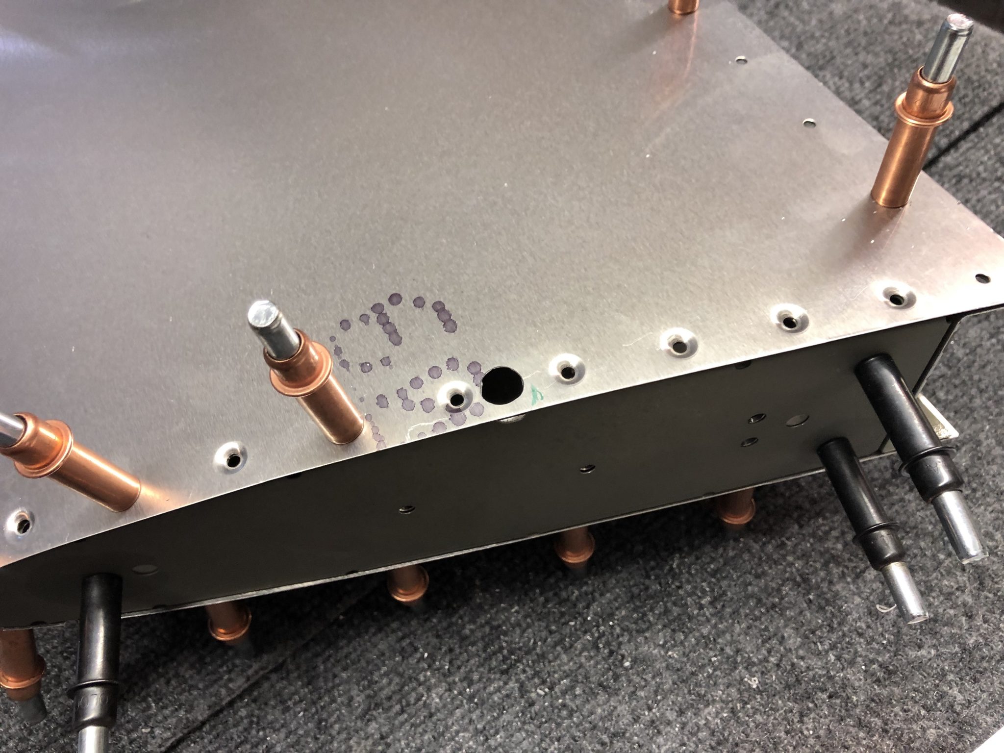
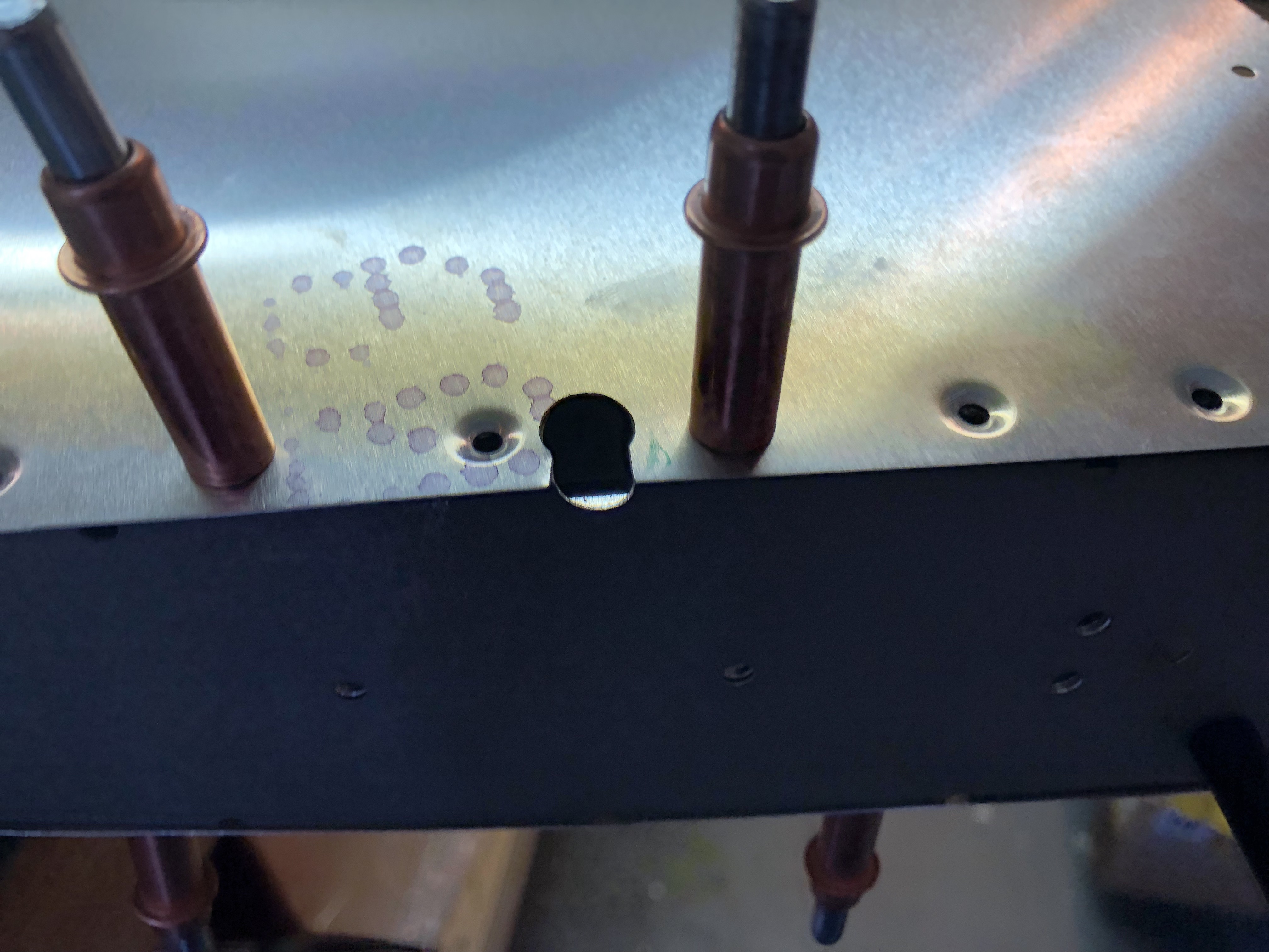
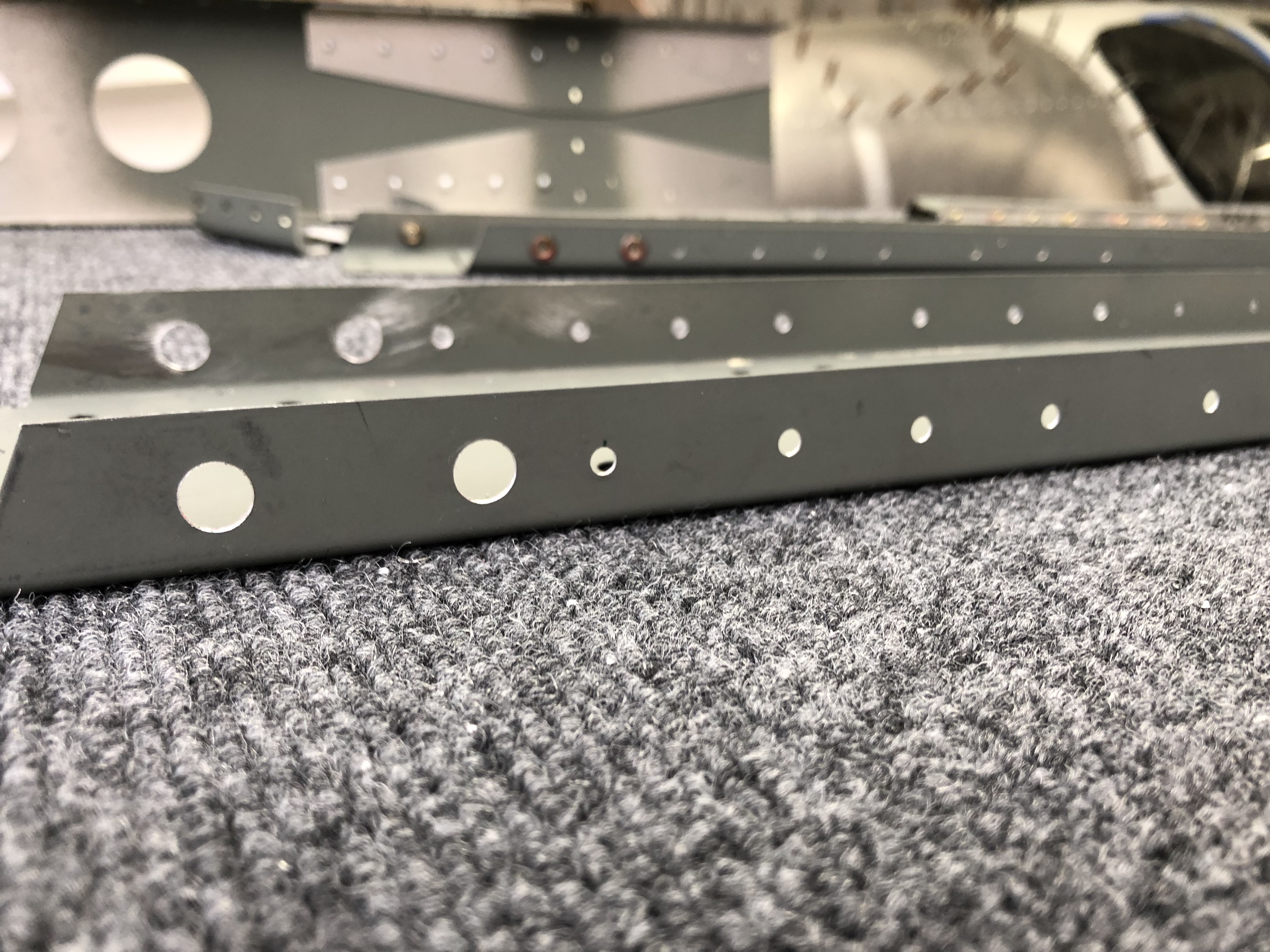
First I had to make another hole to run the Antenna wire through the top rib since the factory plans assume that you either install the light or the Antenna, but not both. I marked the hole location using the center punch, then drilled a pilot hole and then used my step-drill bit to up-drill the hole to the right location for the snap bushing to go in.Center punch to mark the hole location Pilot hole drilled and ready to be drilled up using a step drill bit Finished hole and snap bushing installed

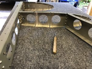
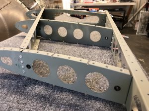
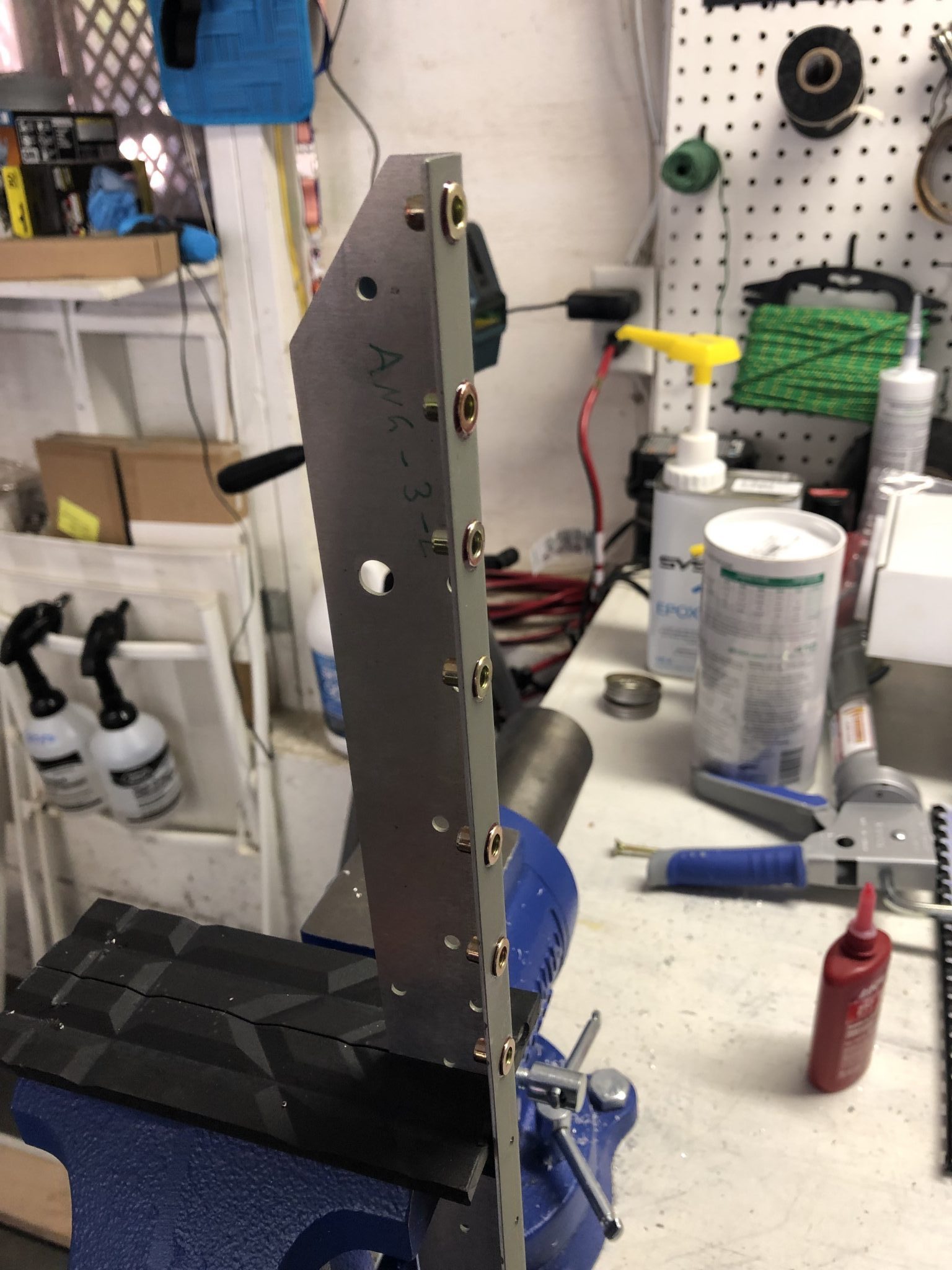
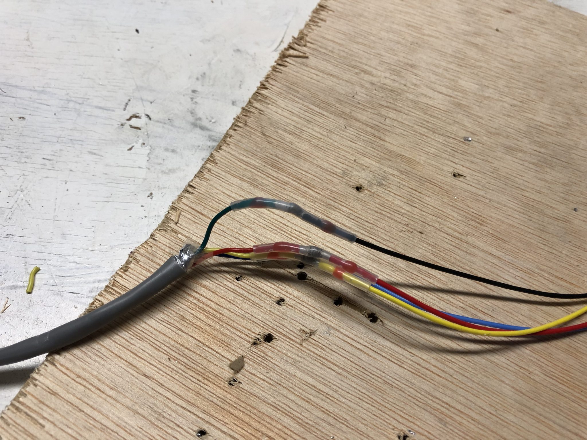
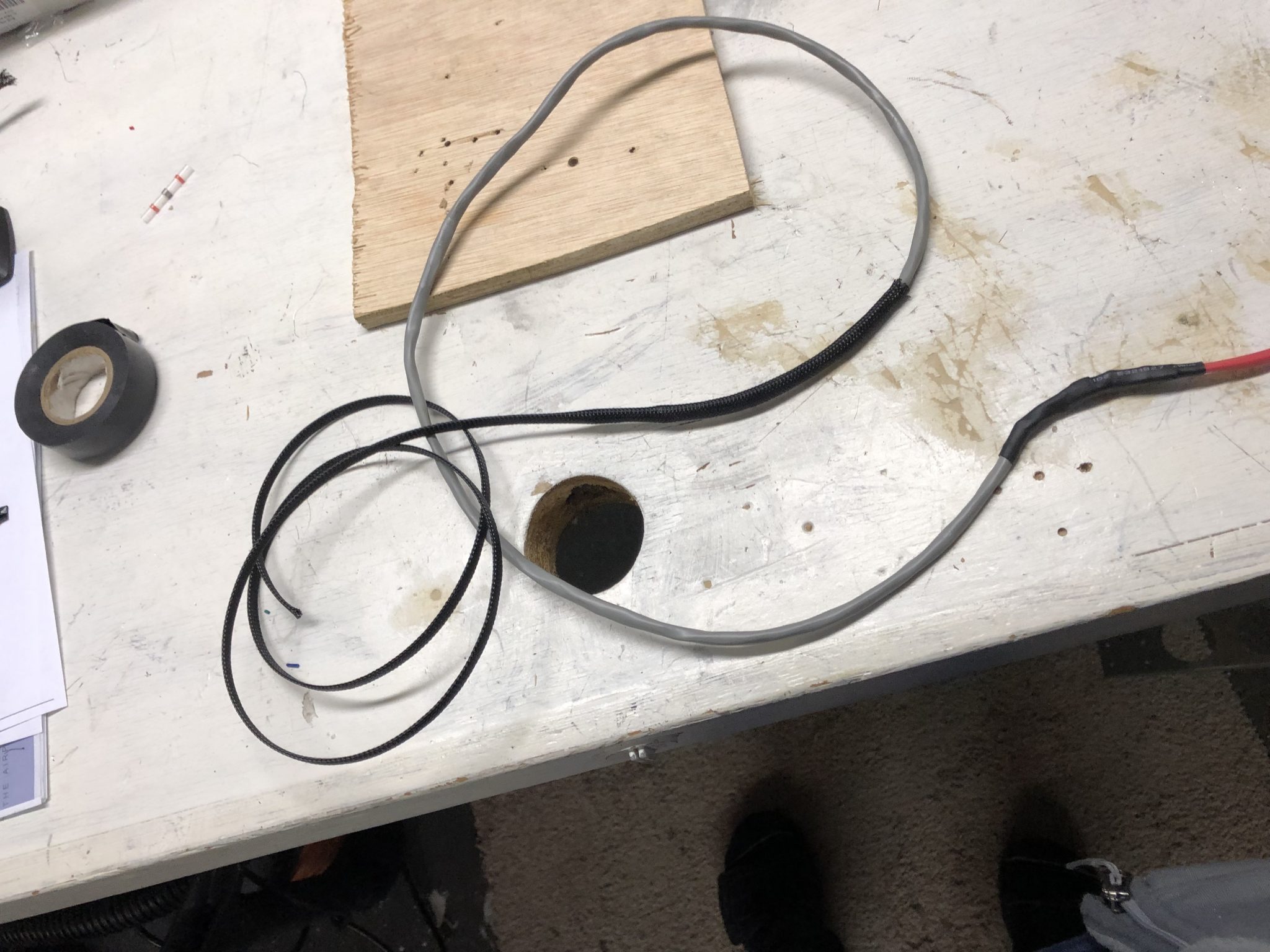
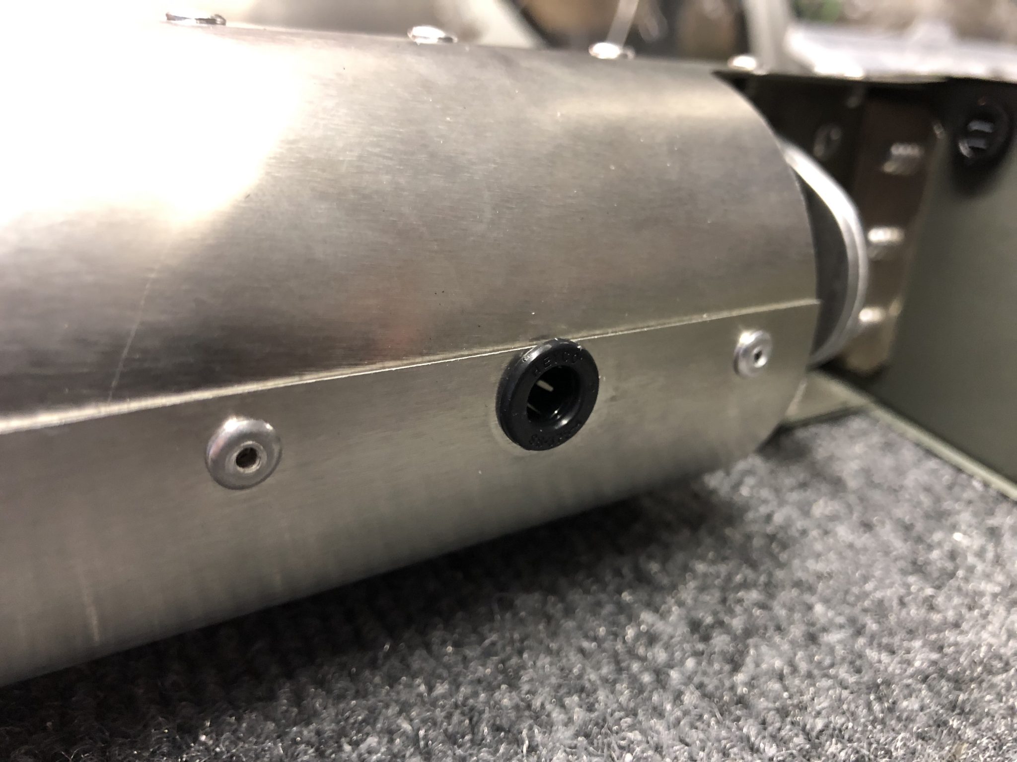
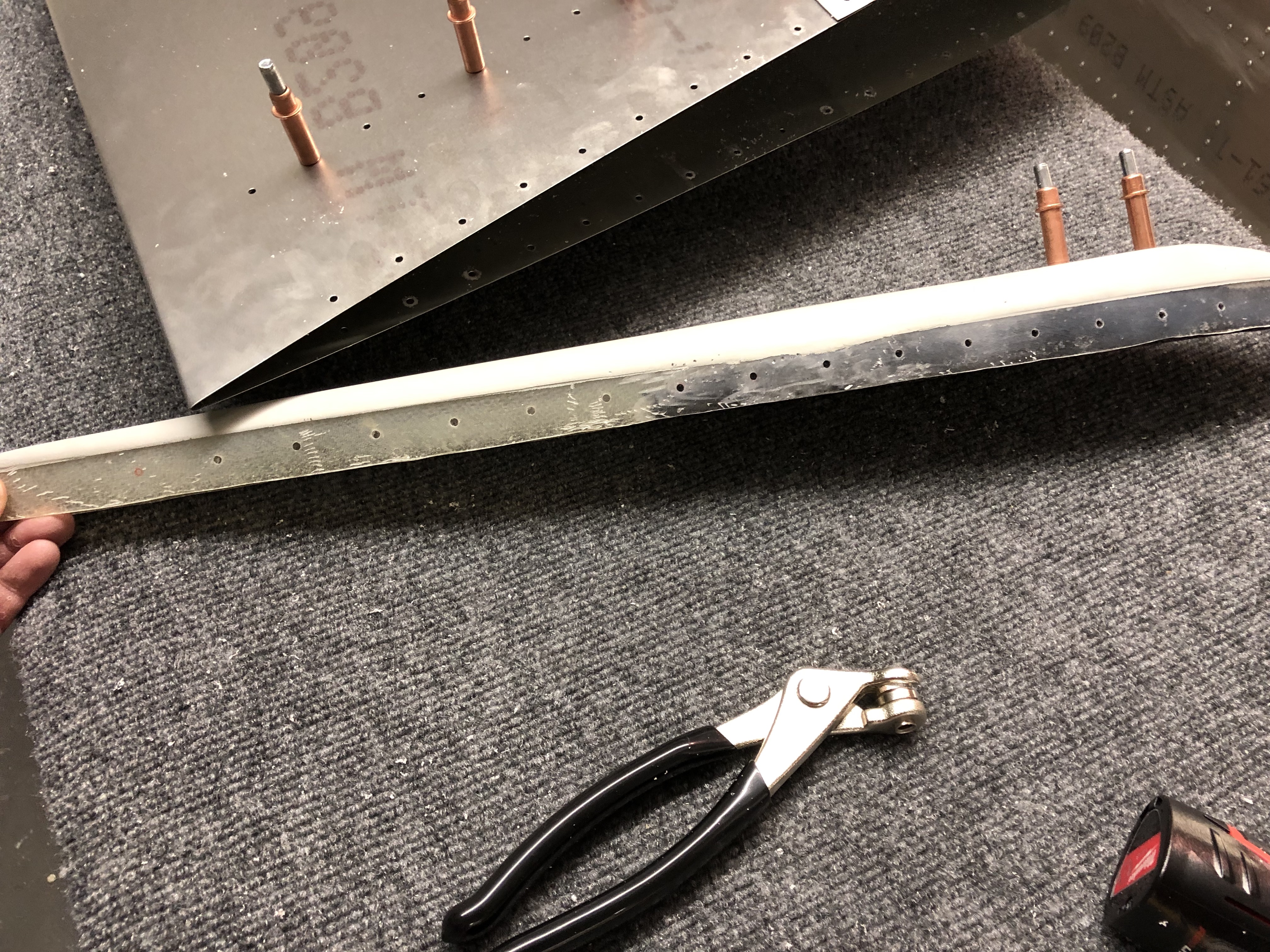
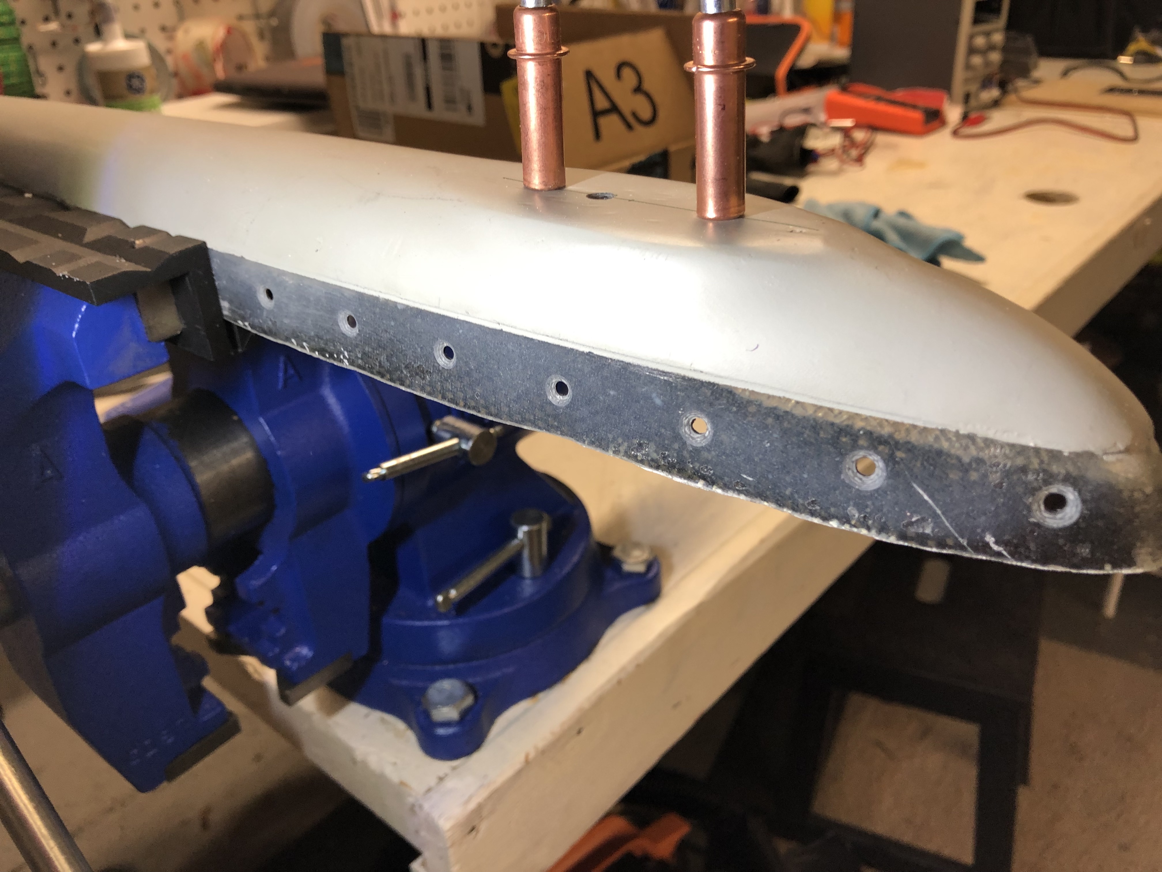
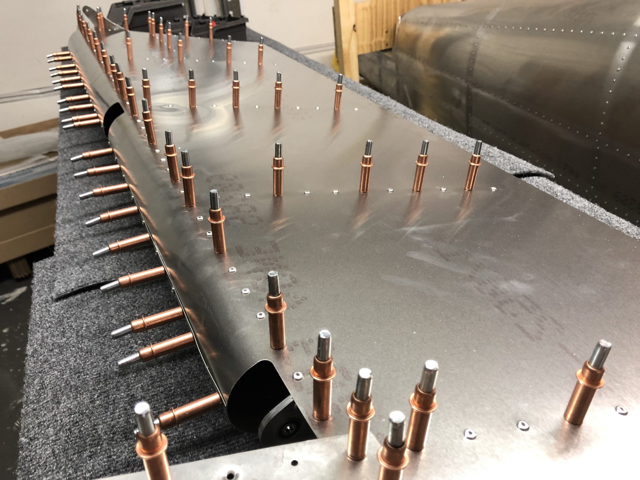
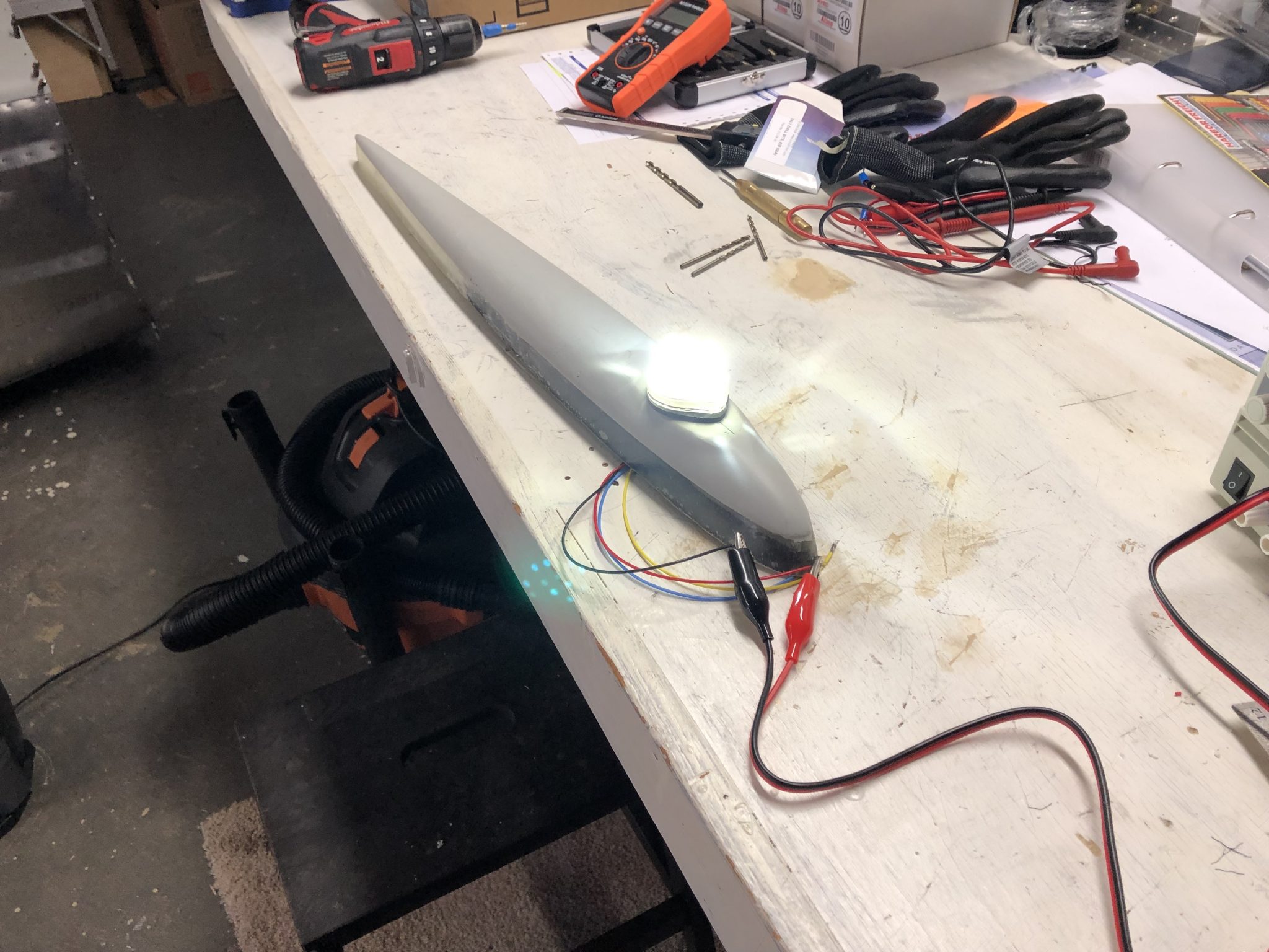
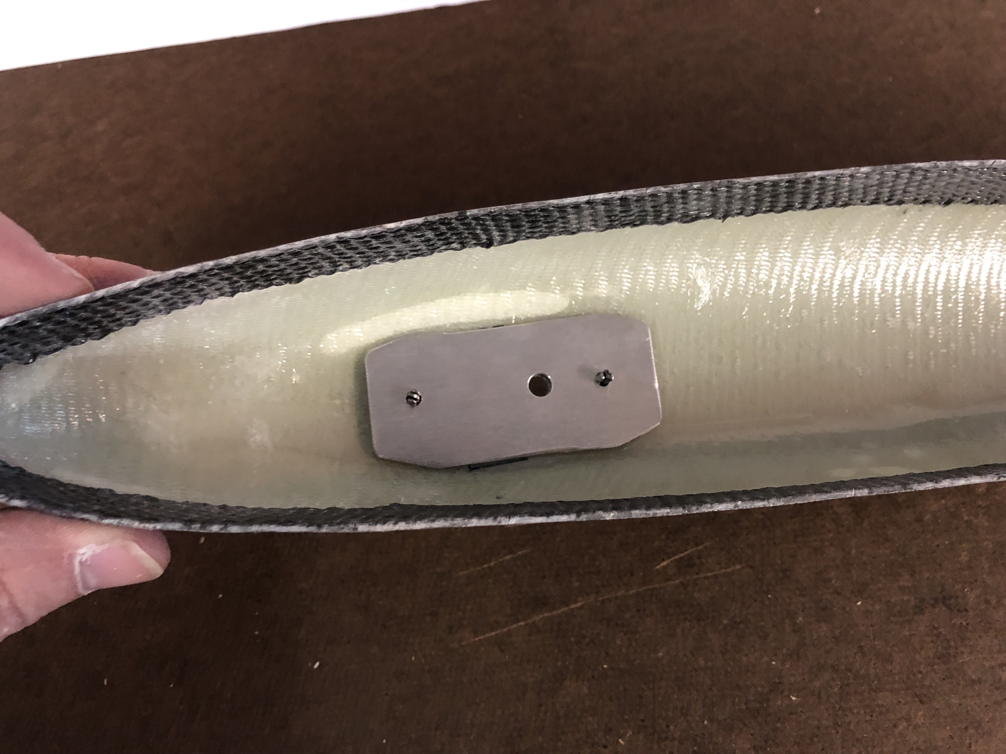
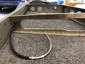
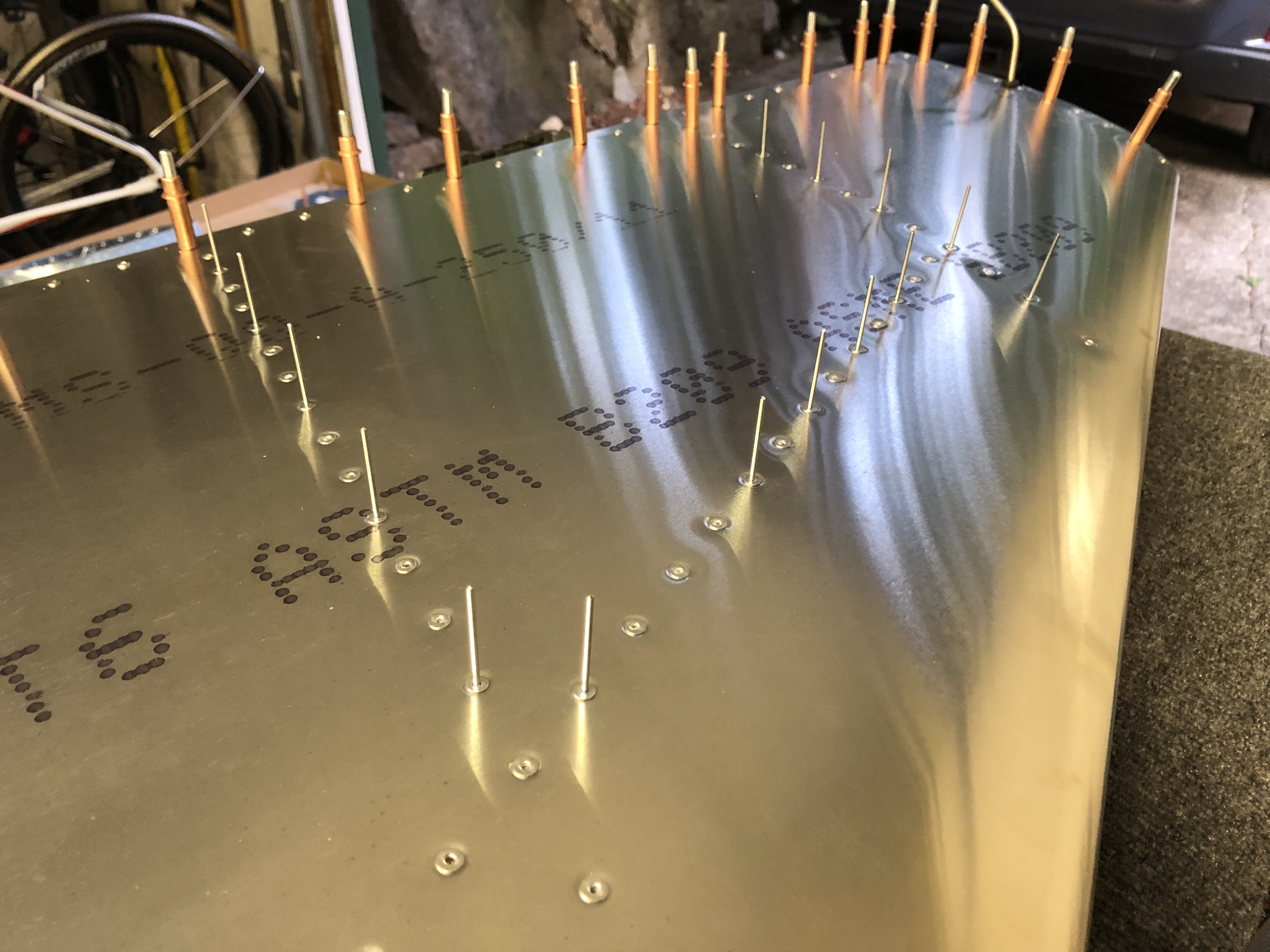
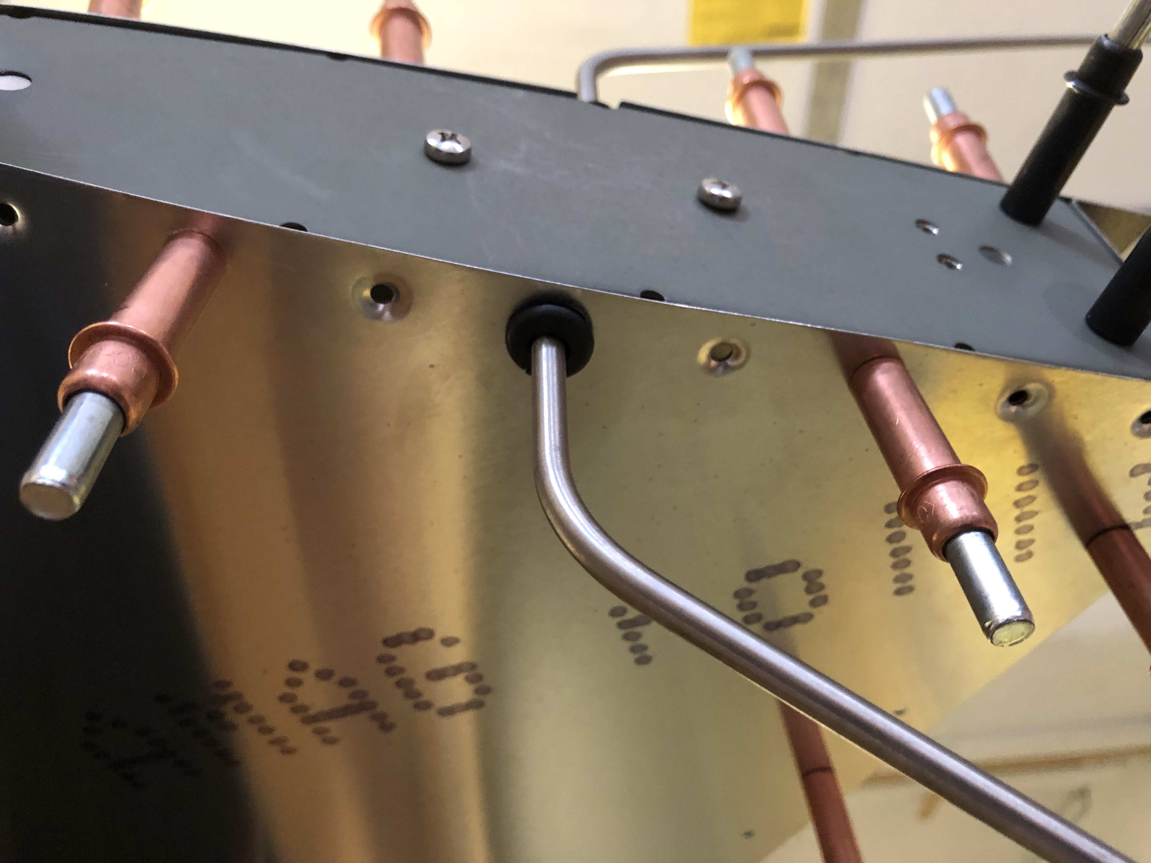
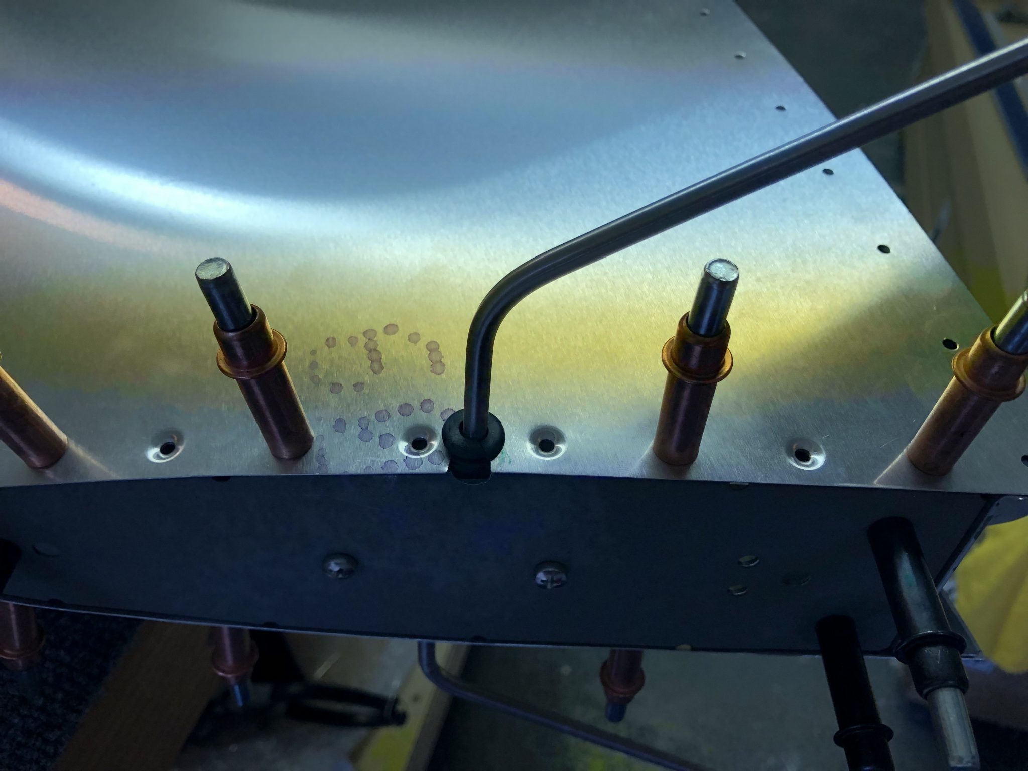
After that was done, I wrapped the wire for the light in some braided sleeving for some extra protection and then ran it through the rear holes. I also installed some flexible edge protection for the hole where the wire will meet the wire from the Rudder.
Wire for the light installed in the Vertical Stabilizer Flexible edge protection

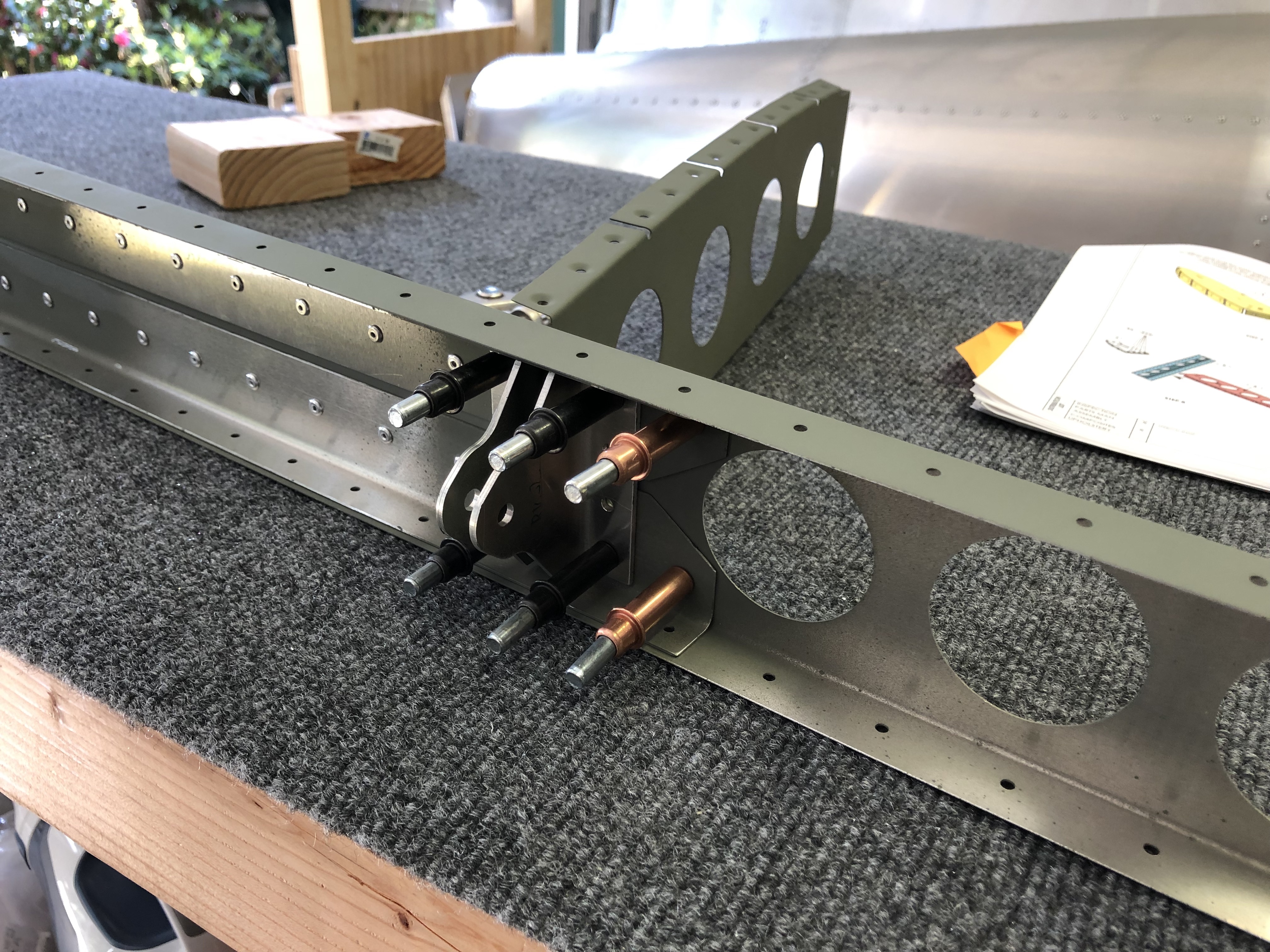
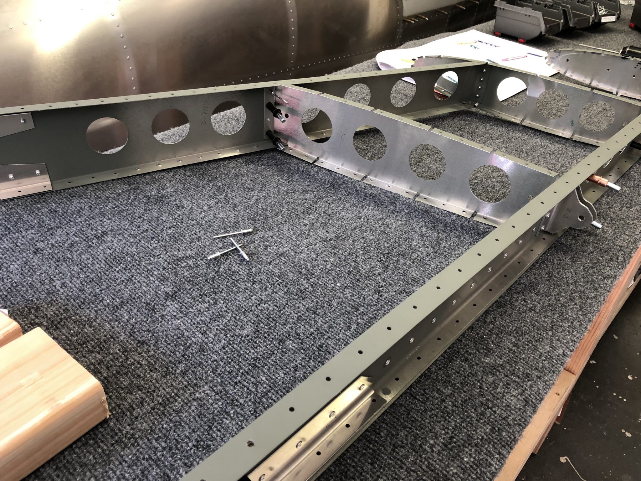
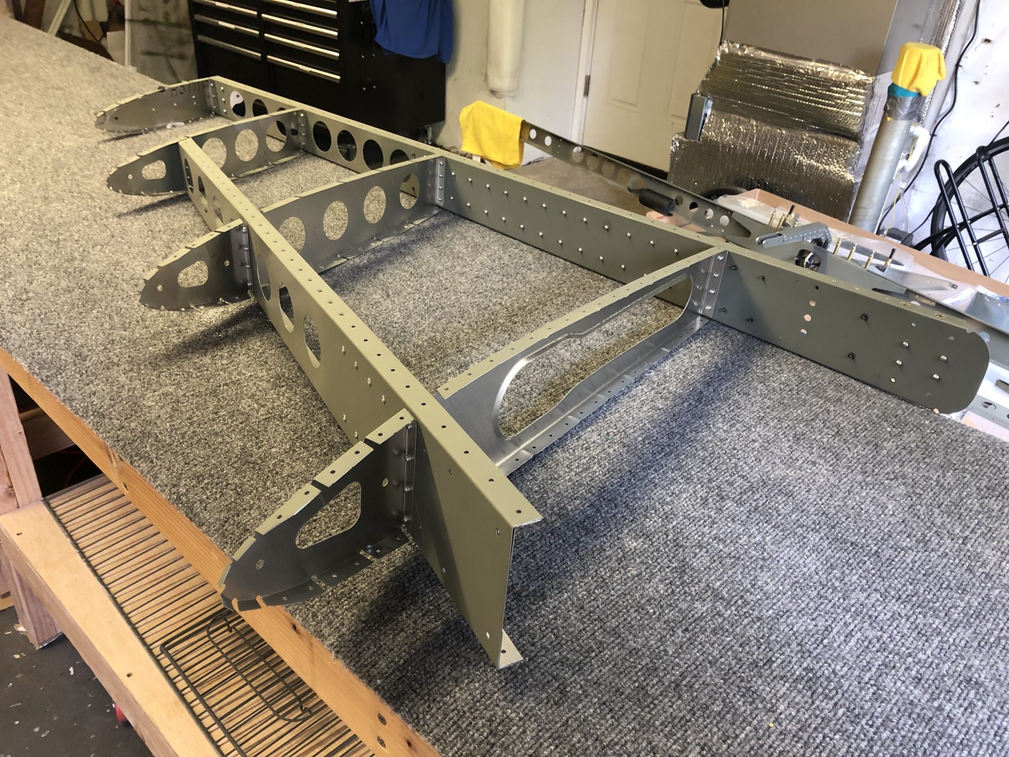
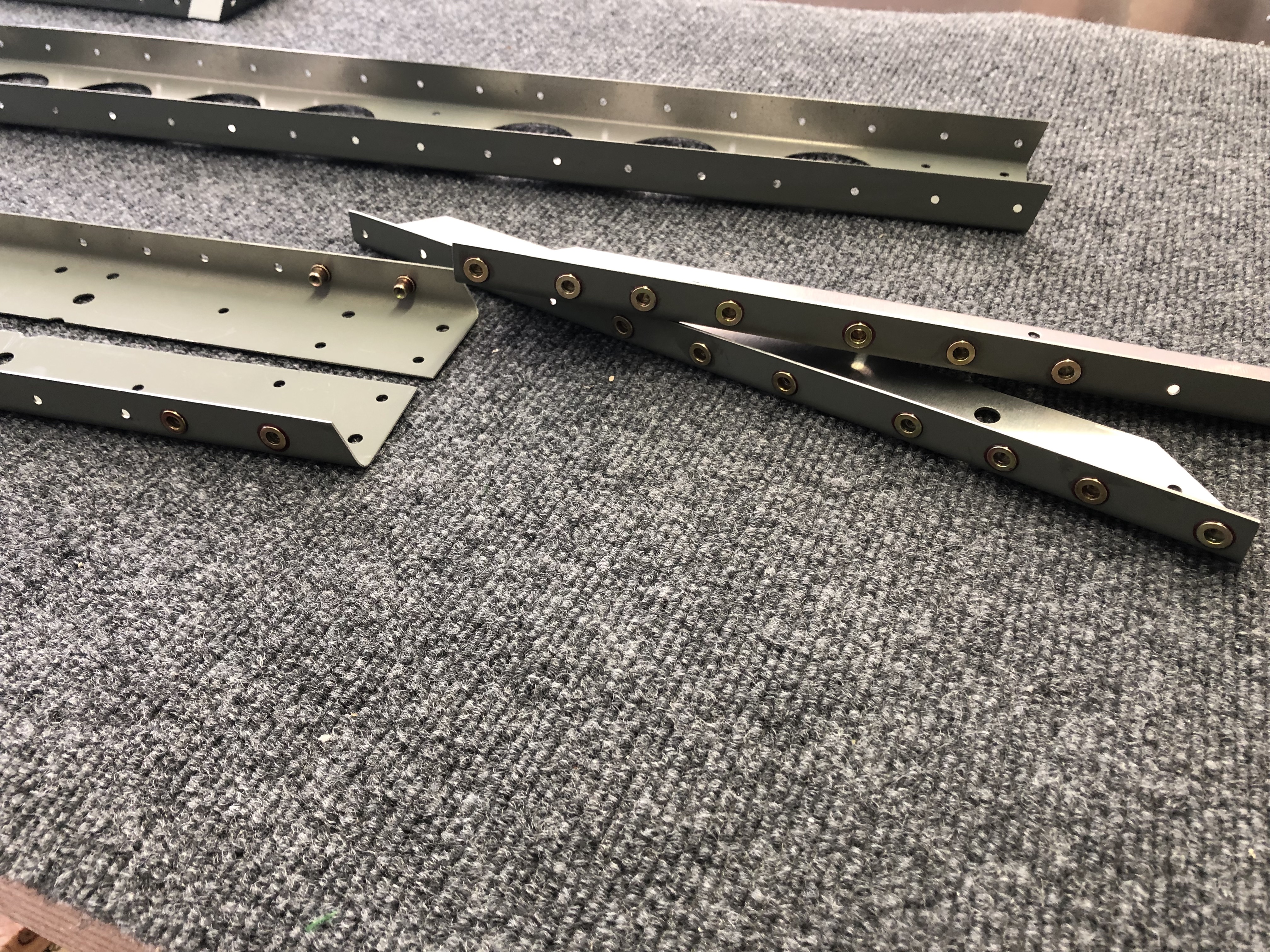
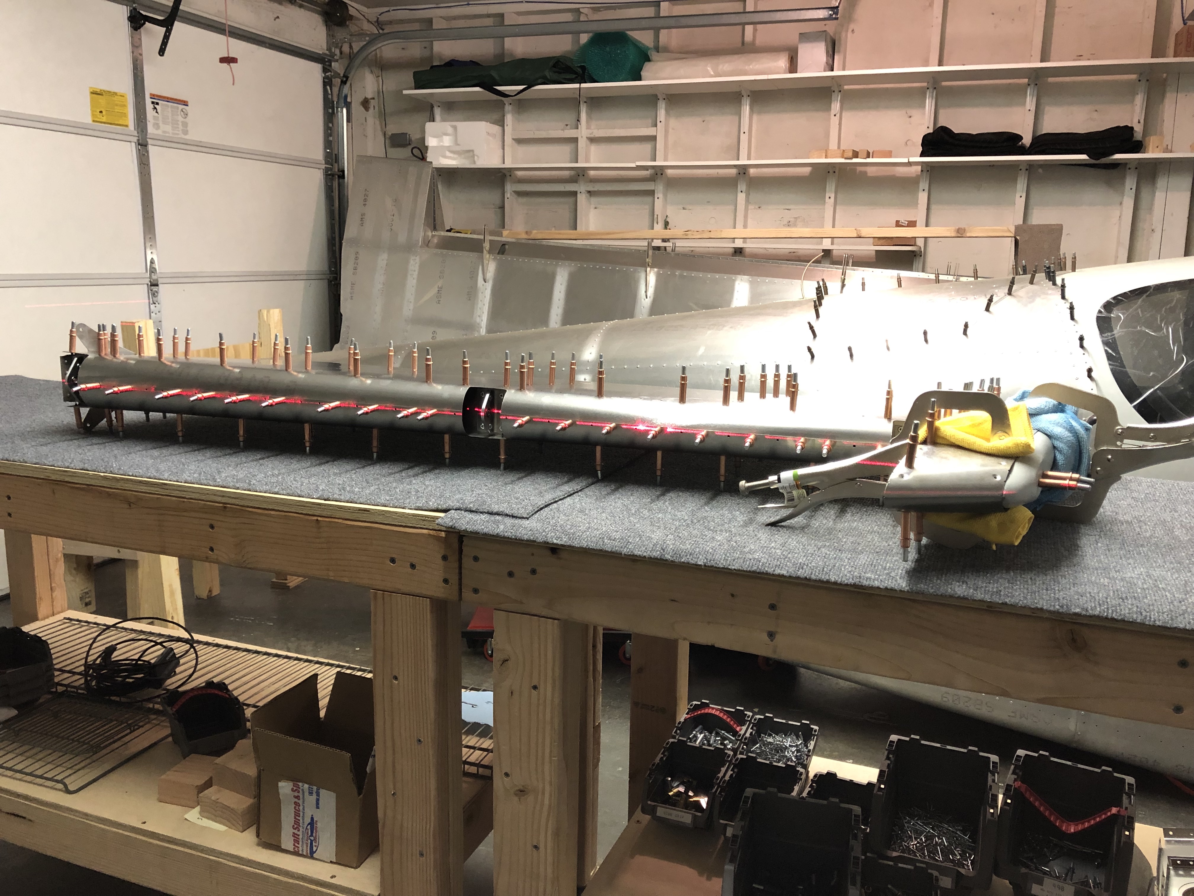
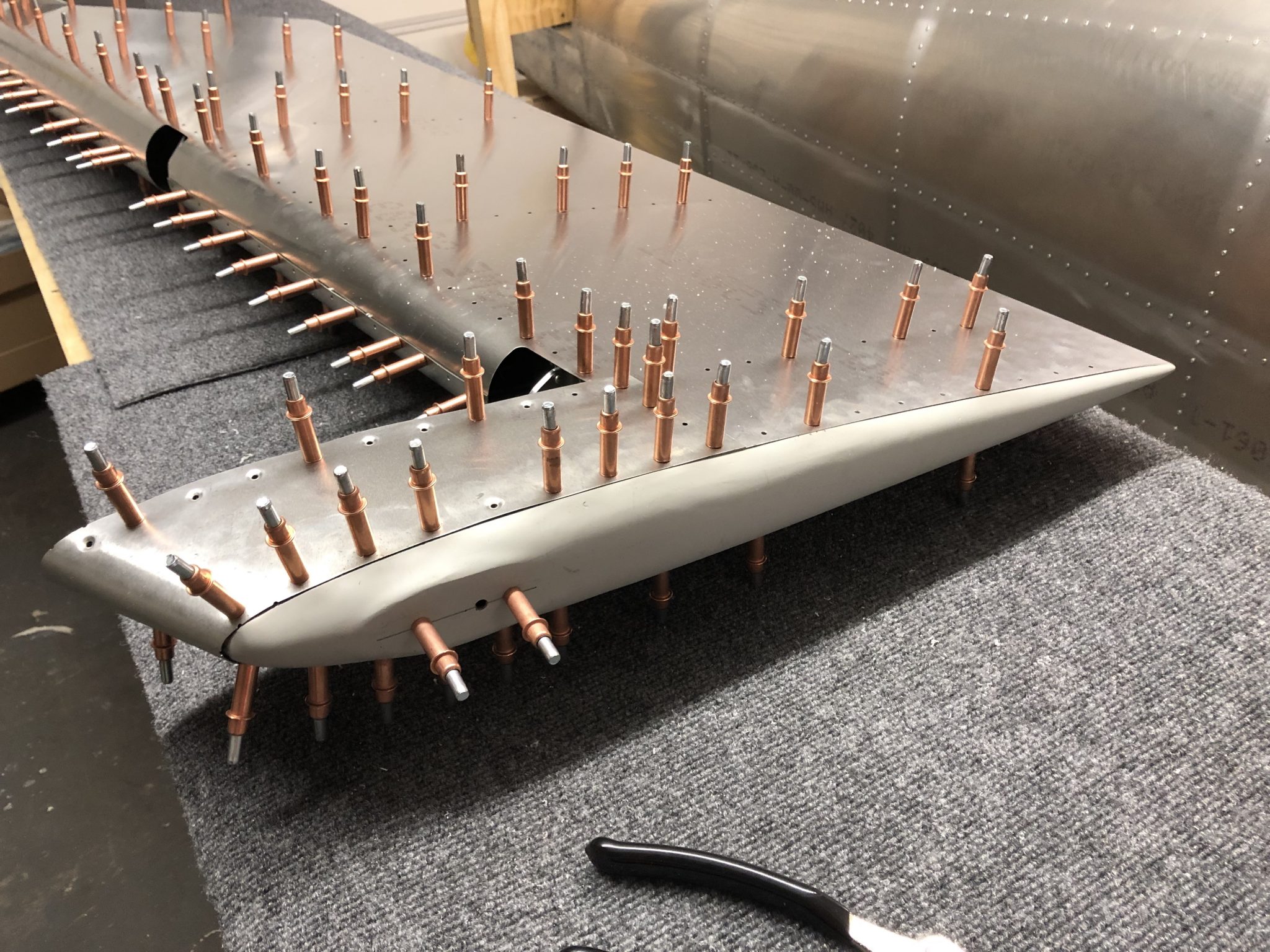
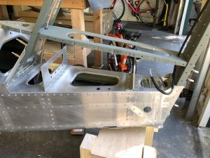
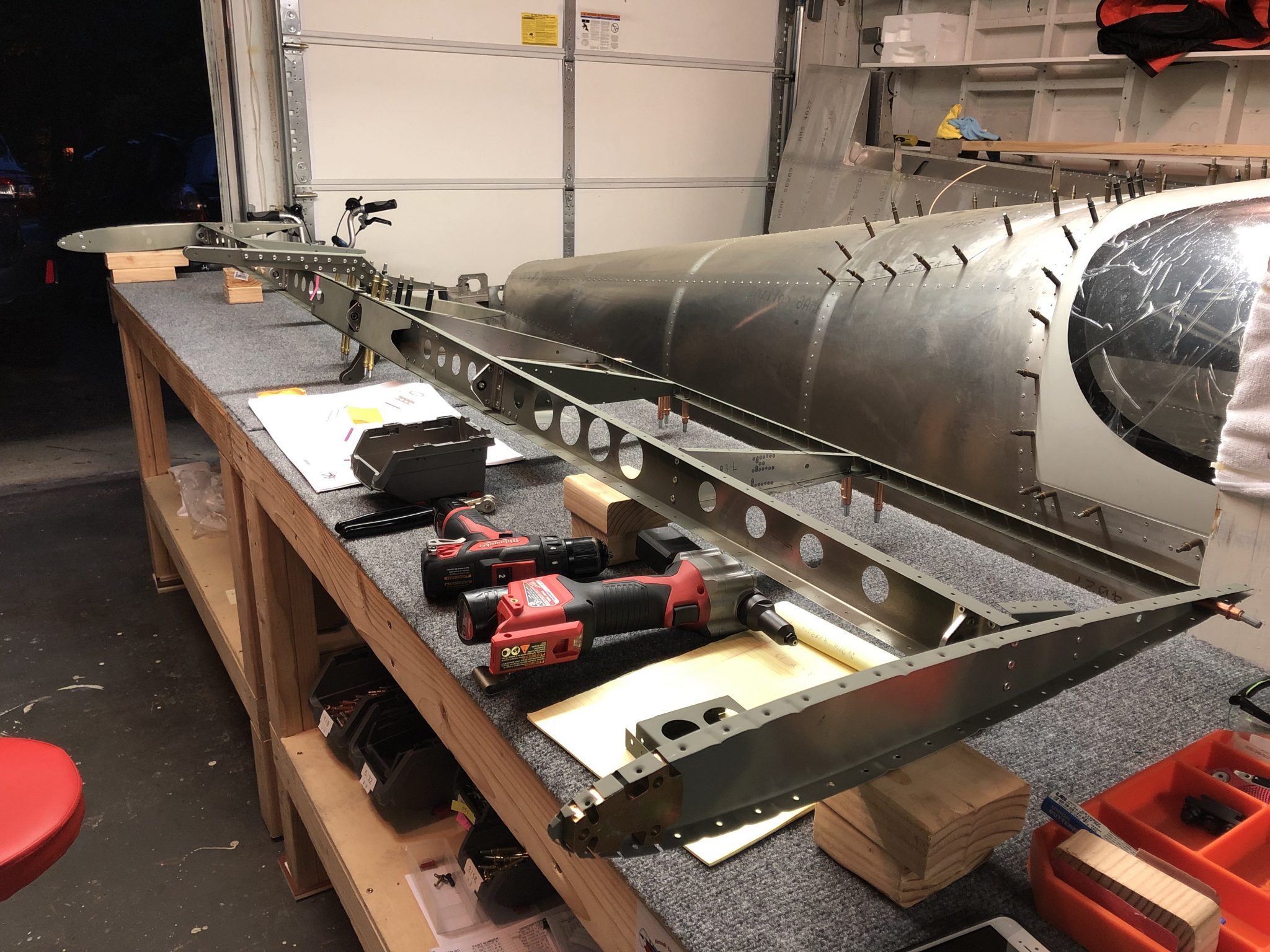
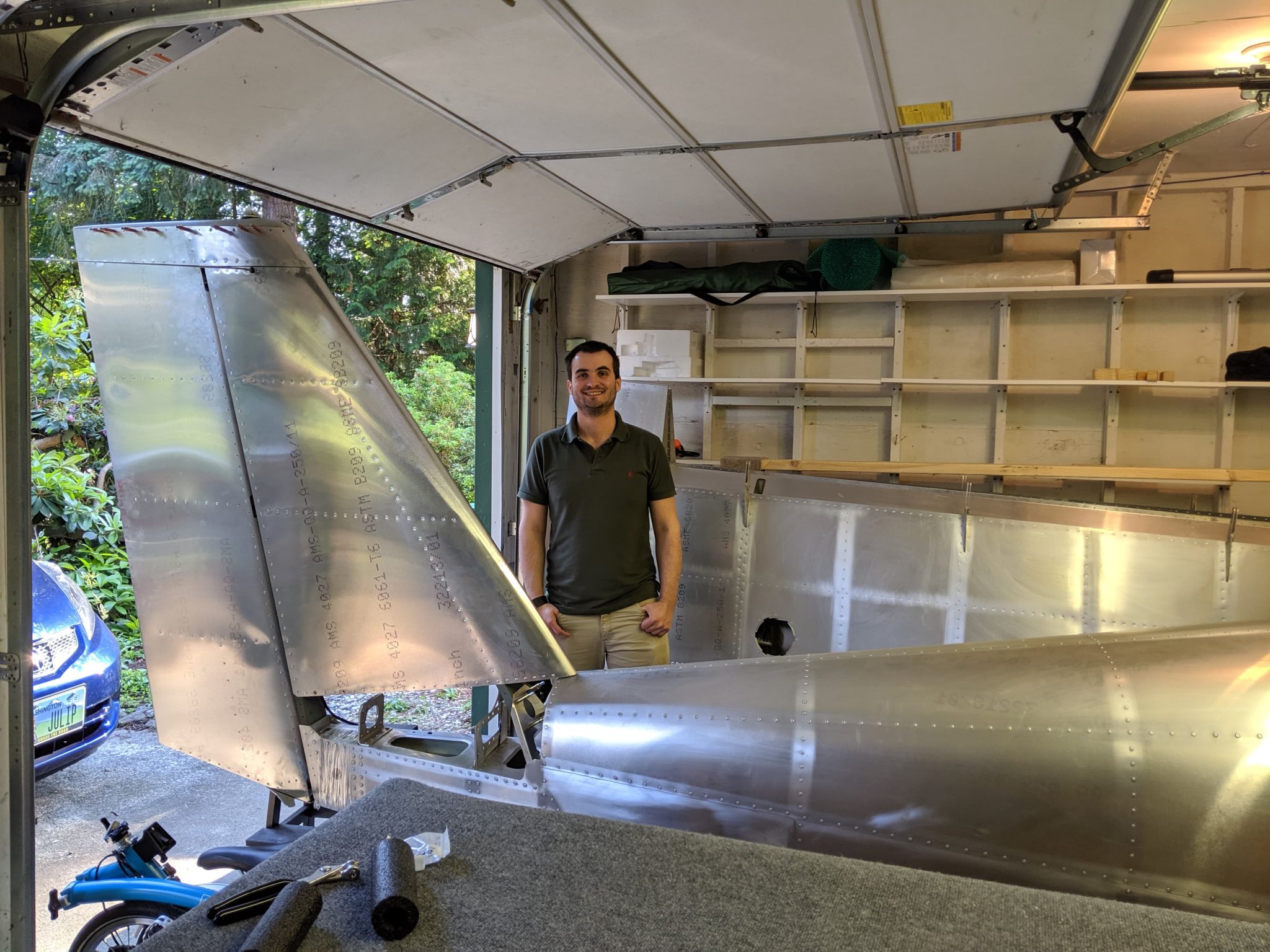
Quick test fit on the Fuselage

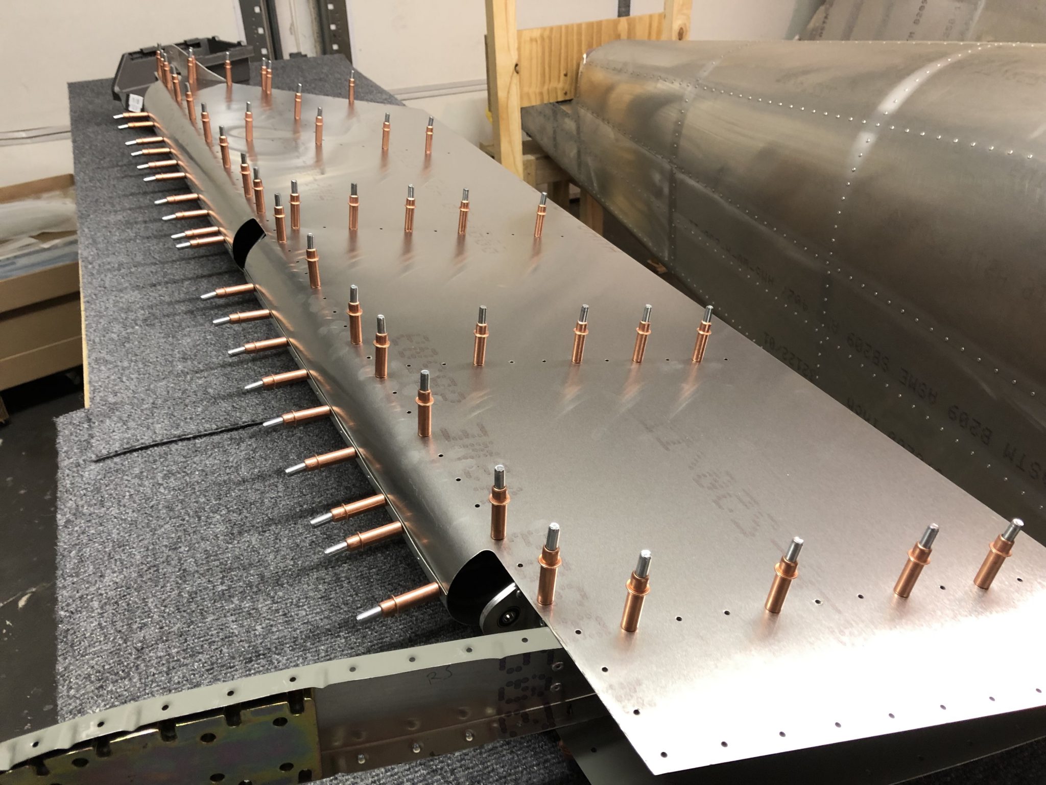
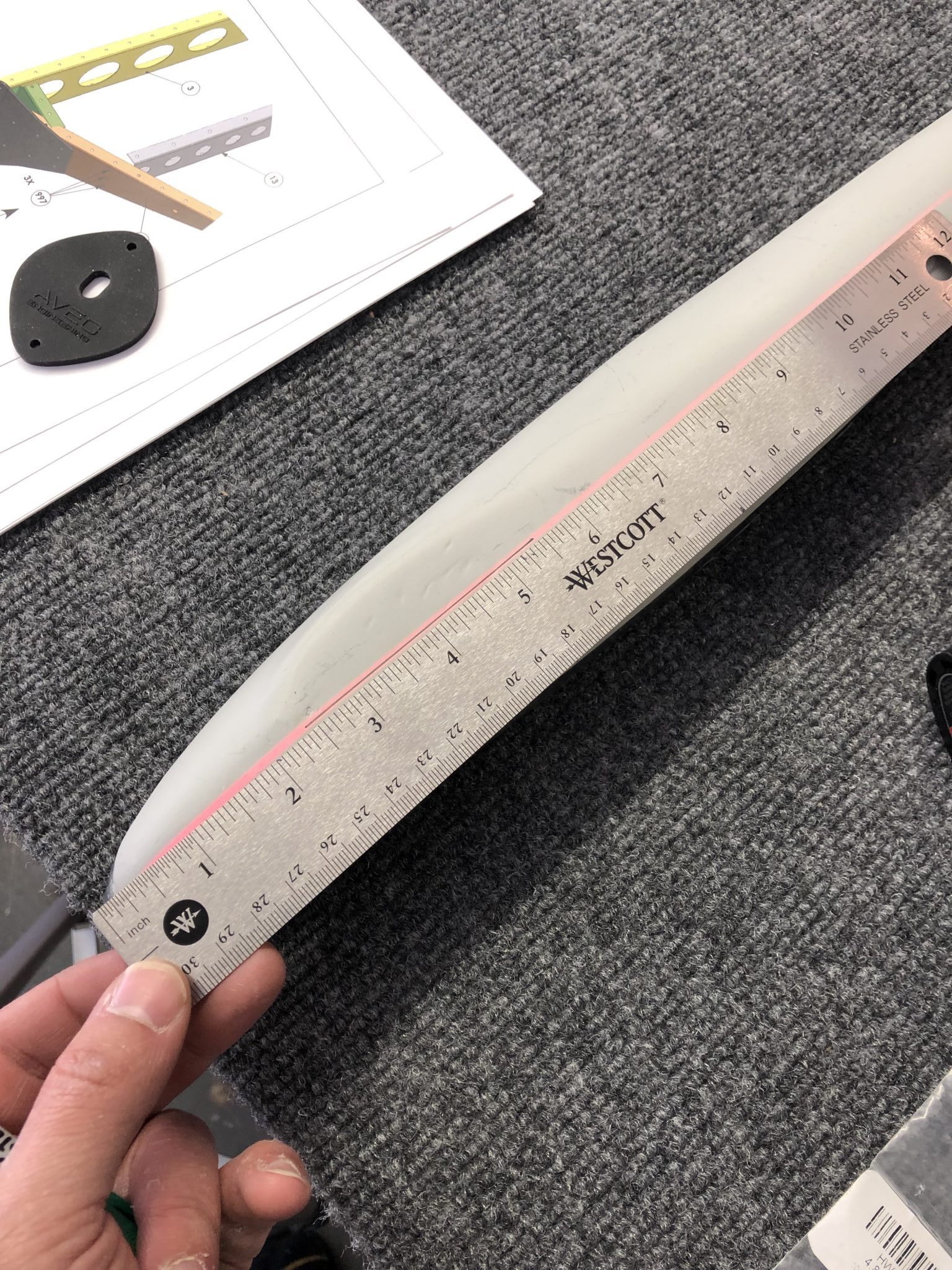
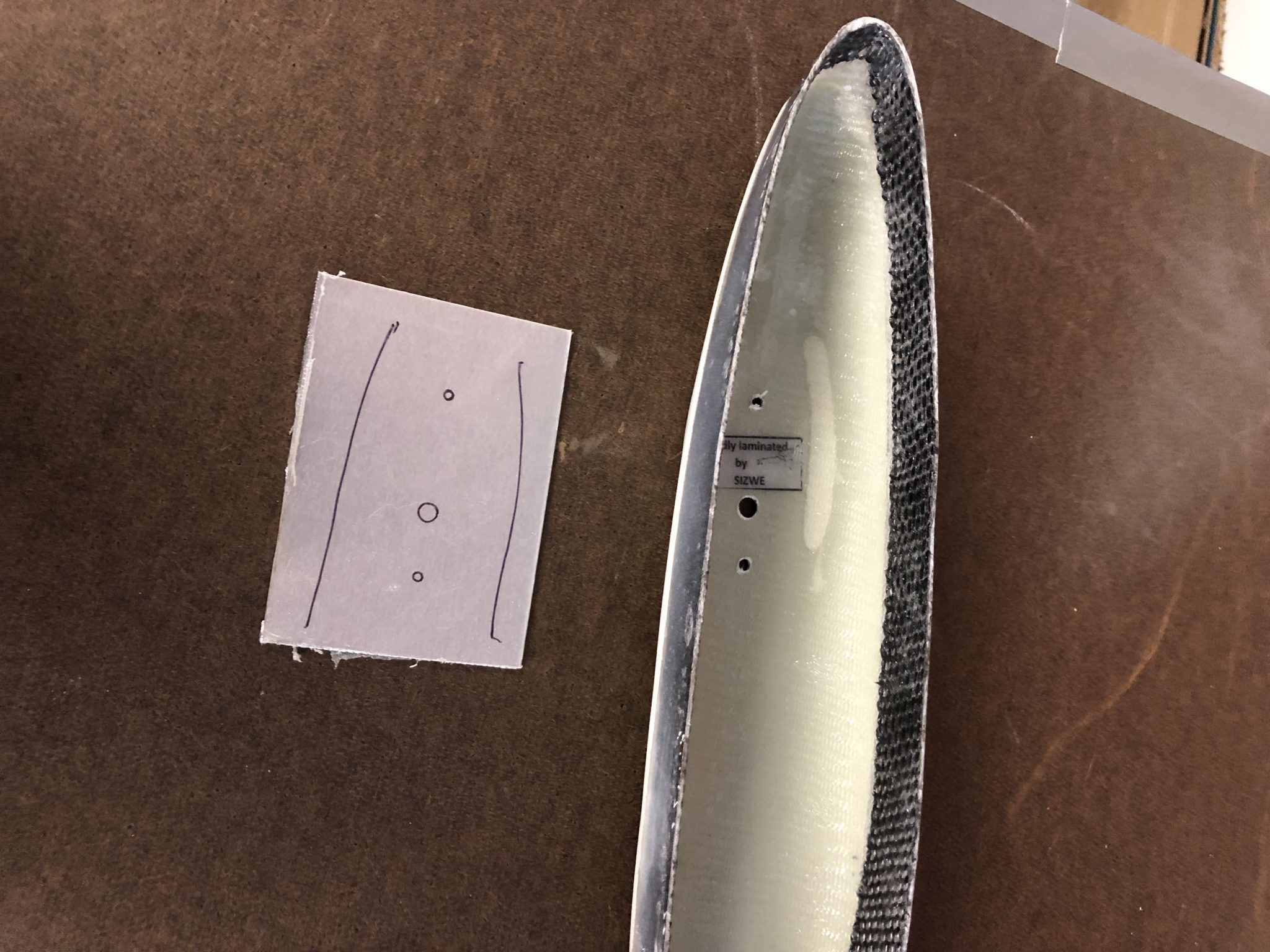
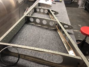
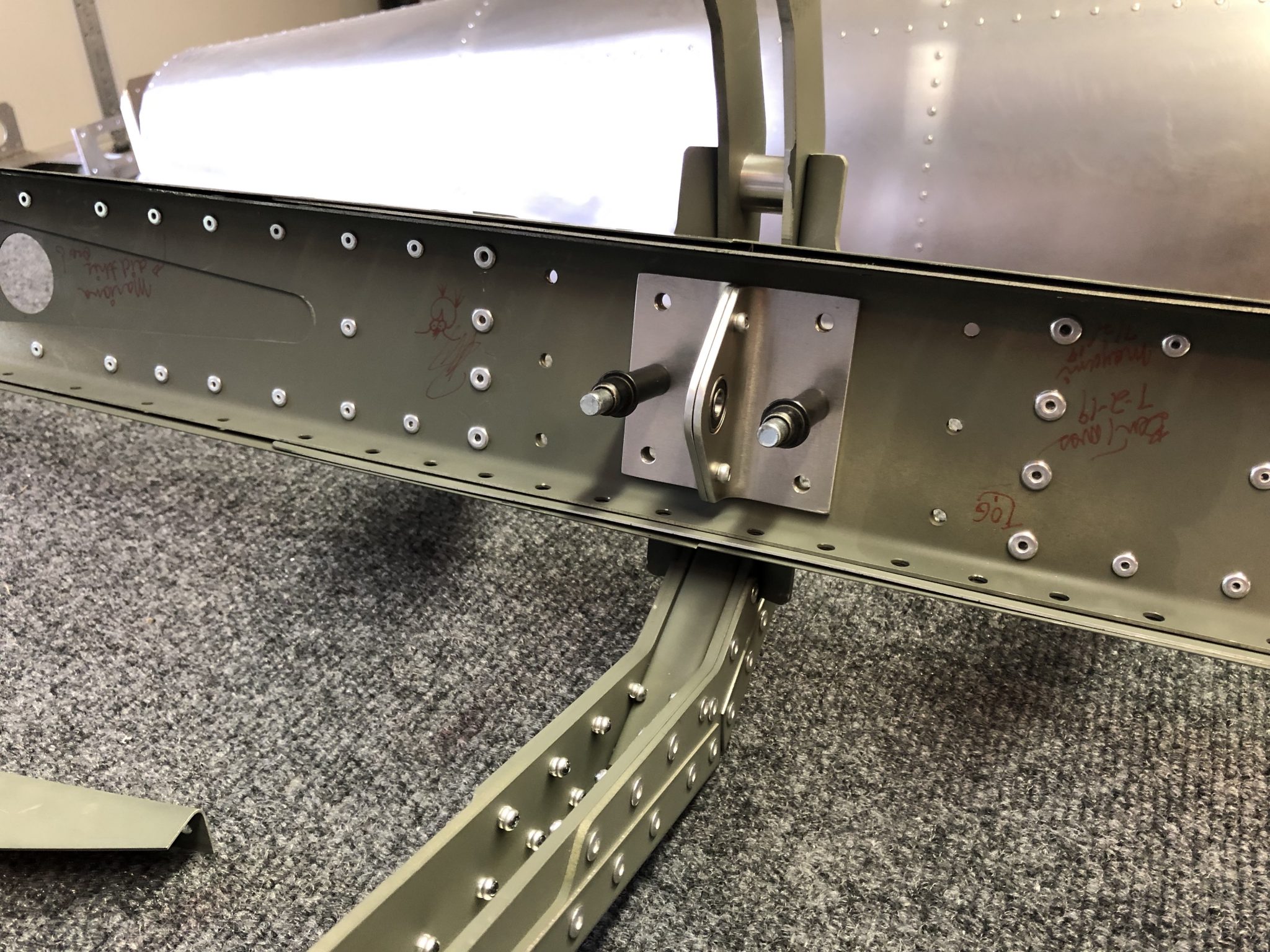
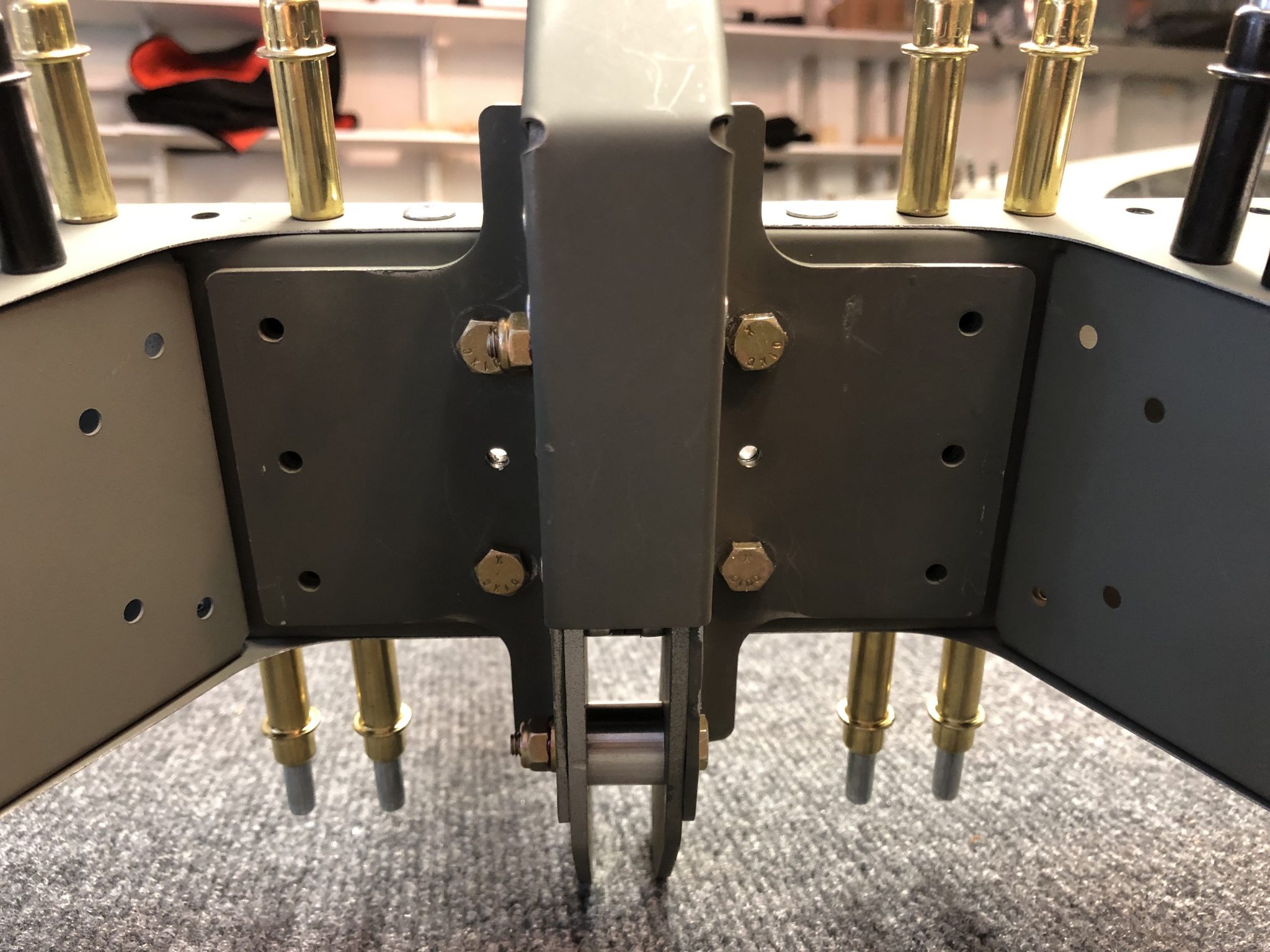
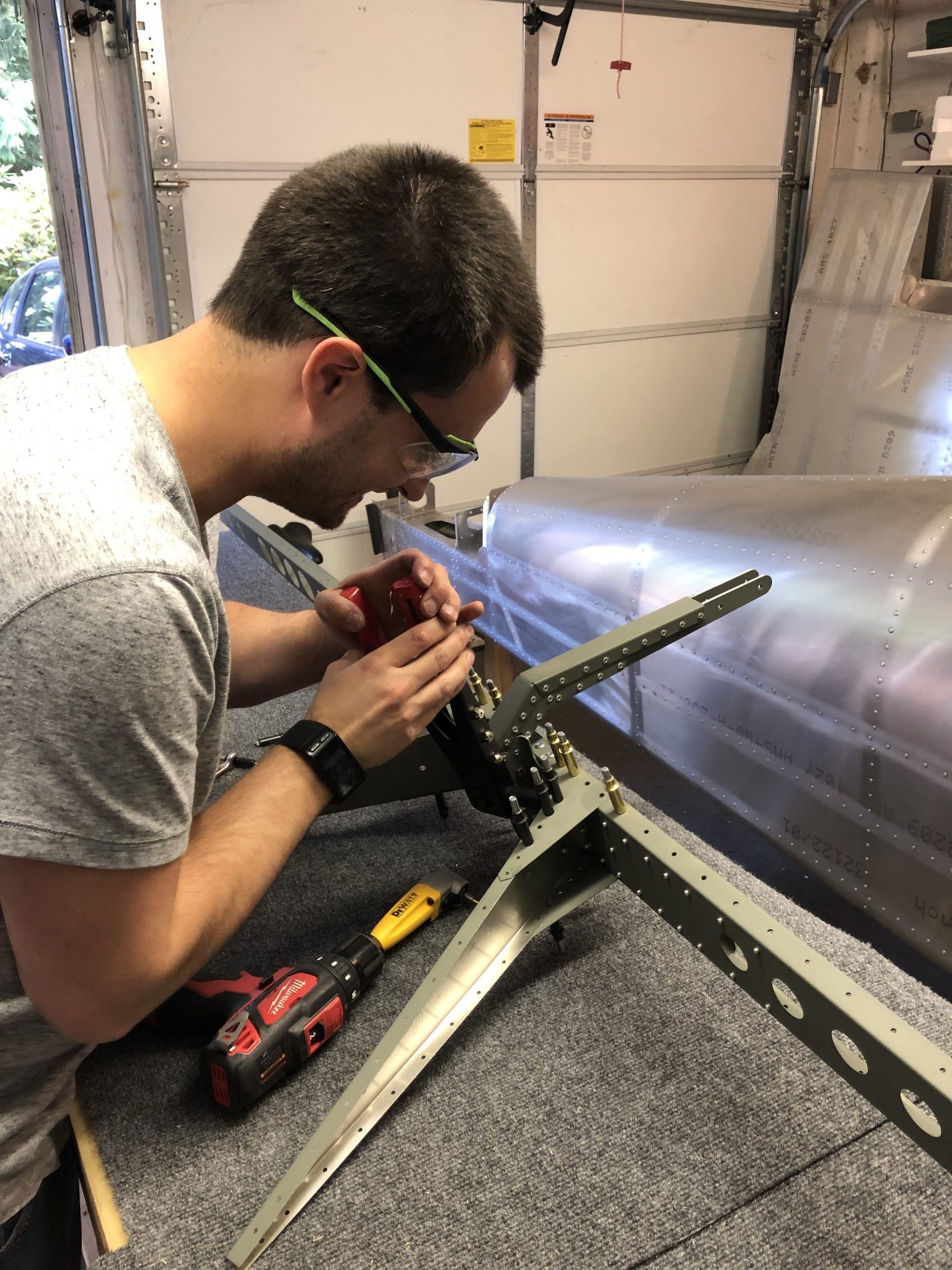
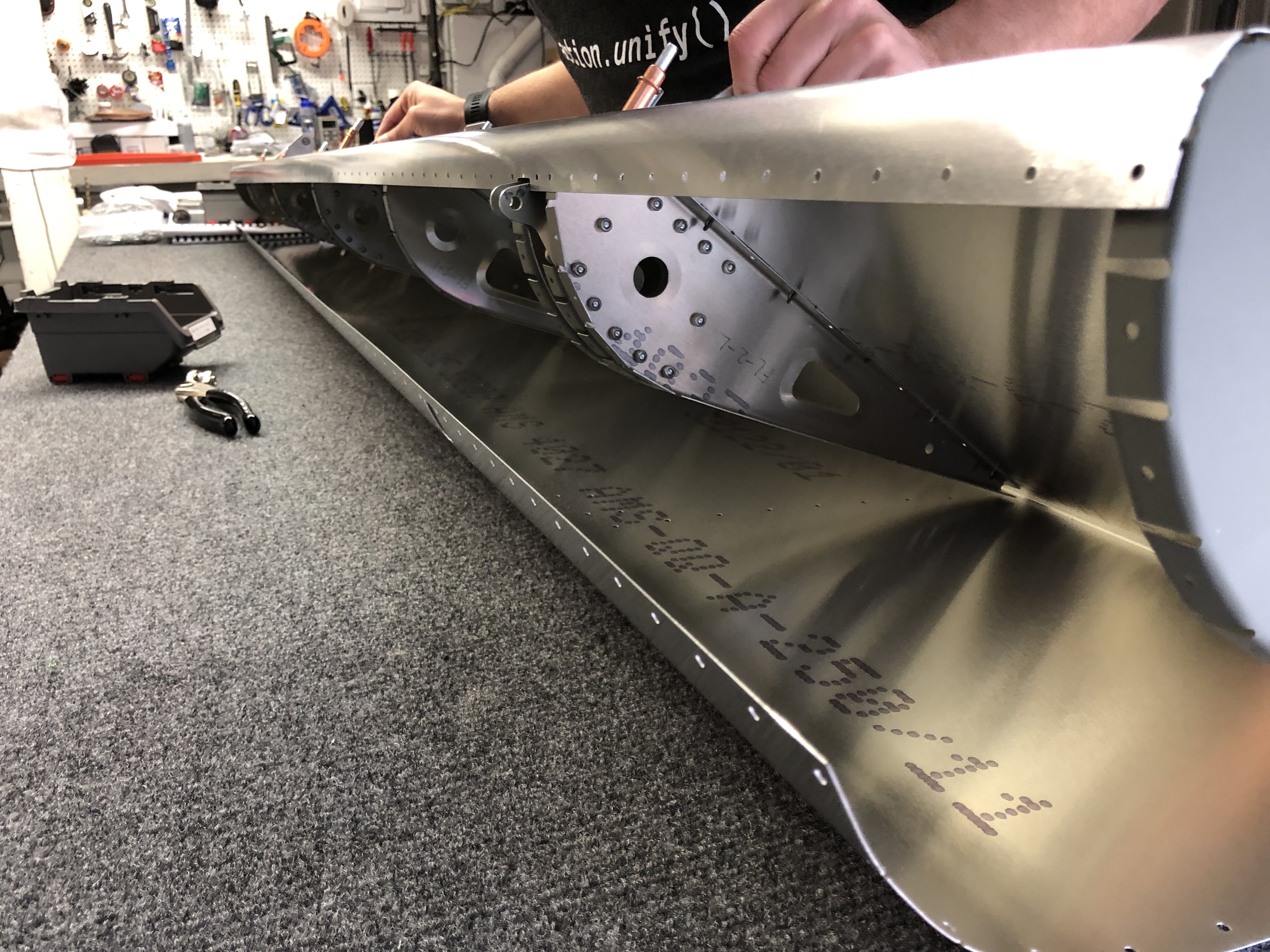
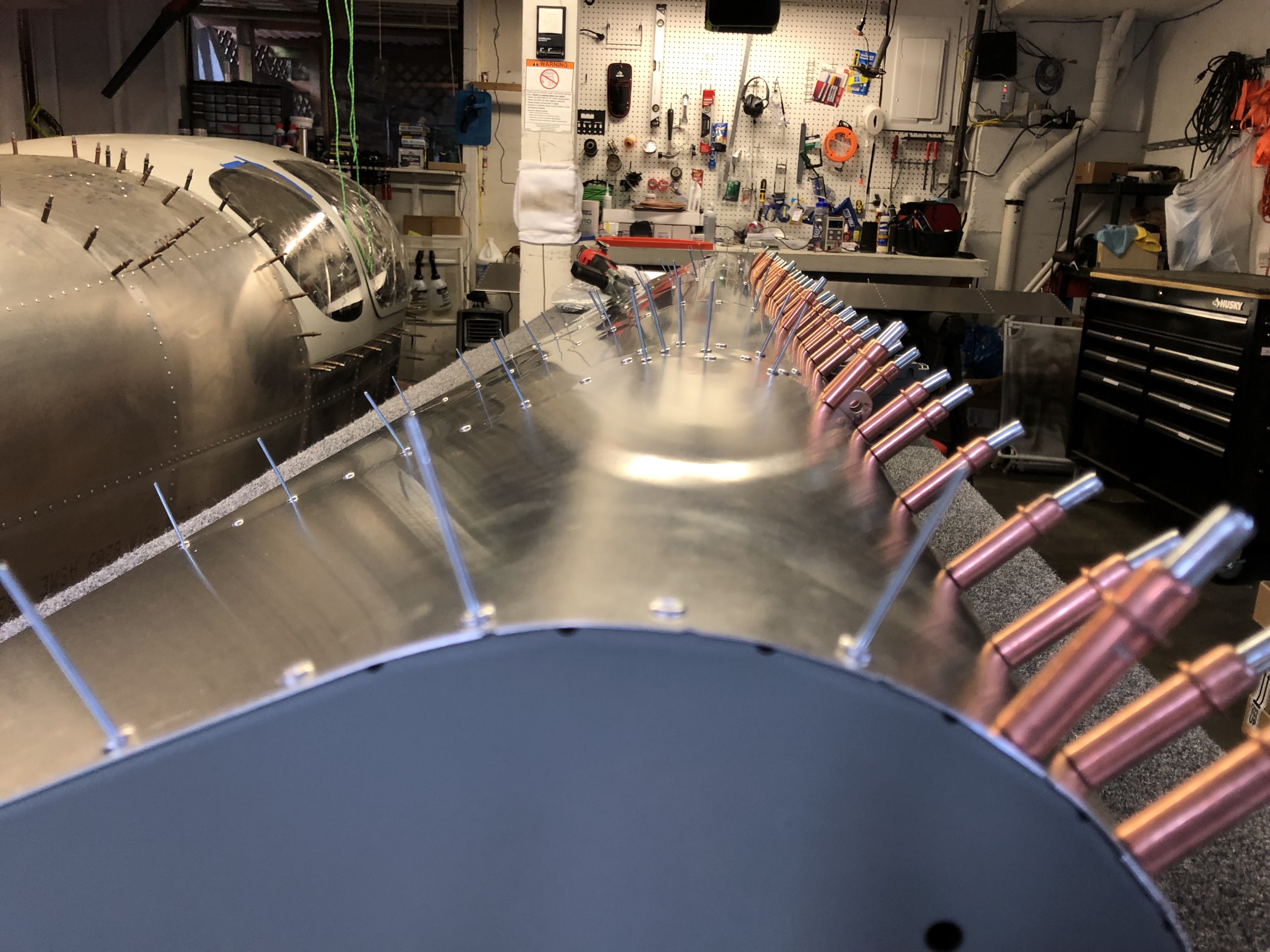
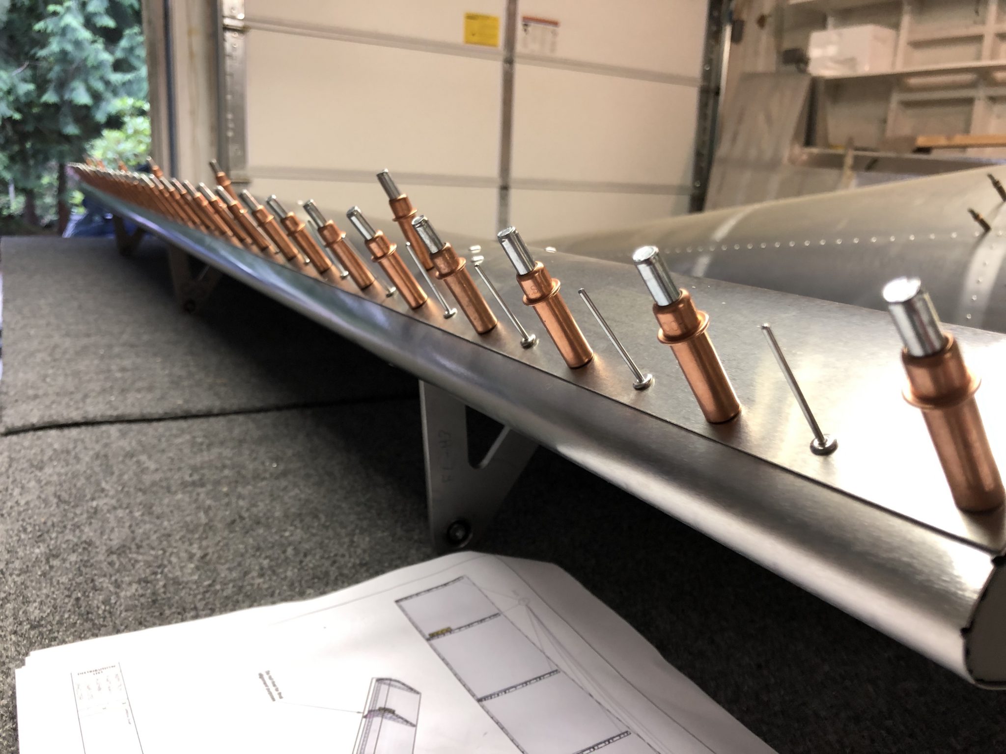
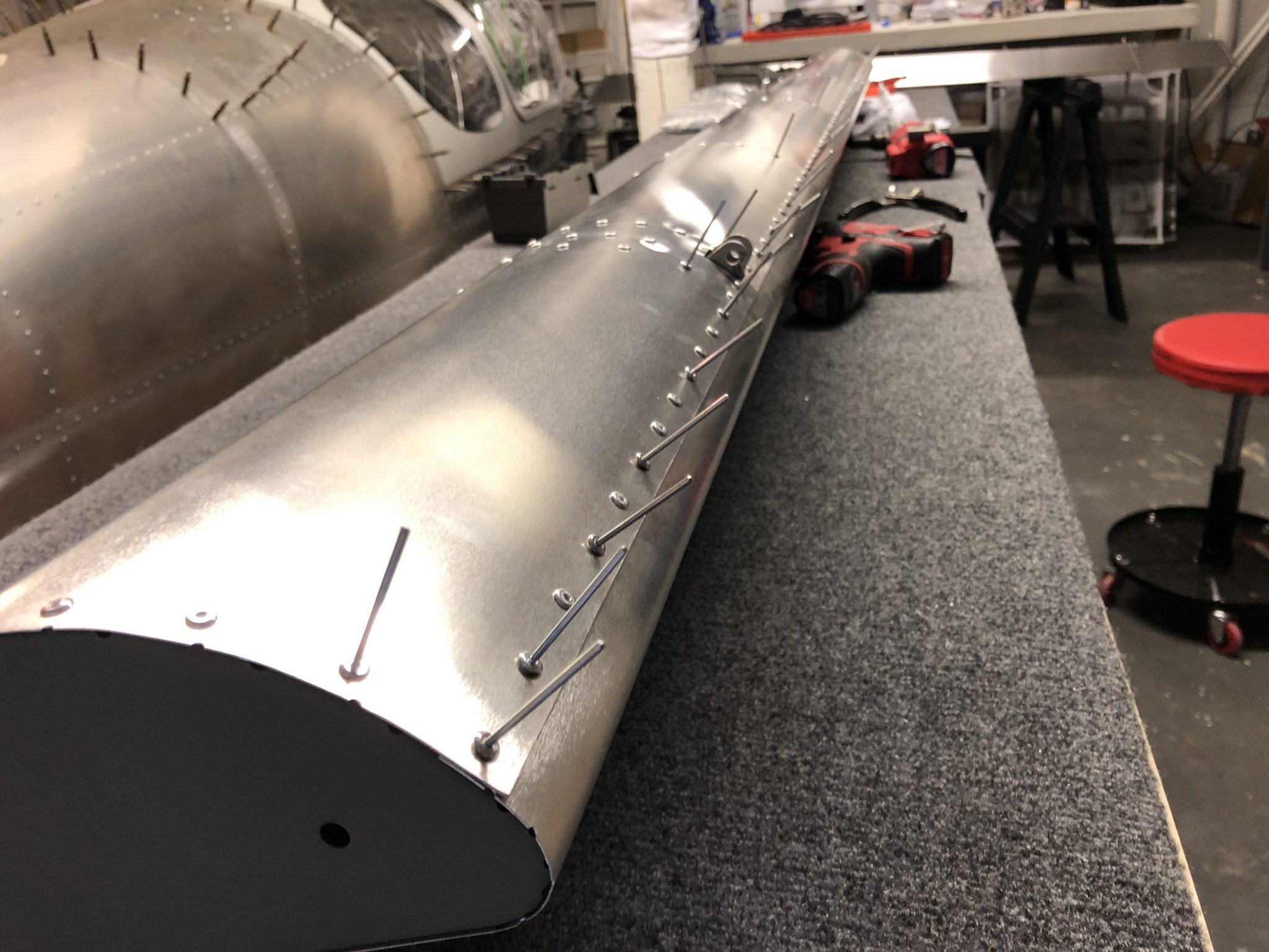
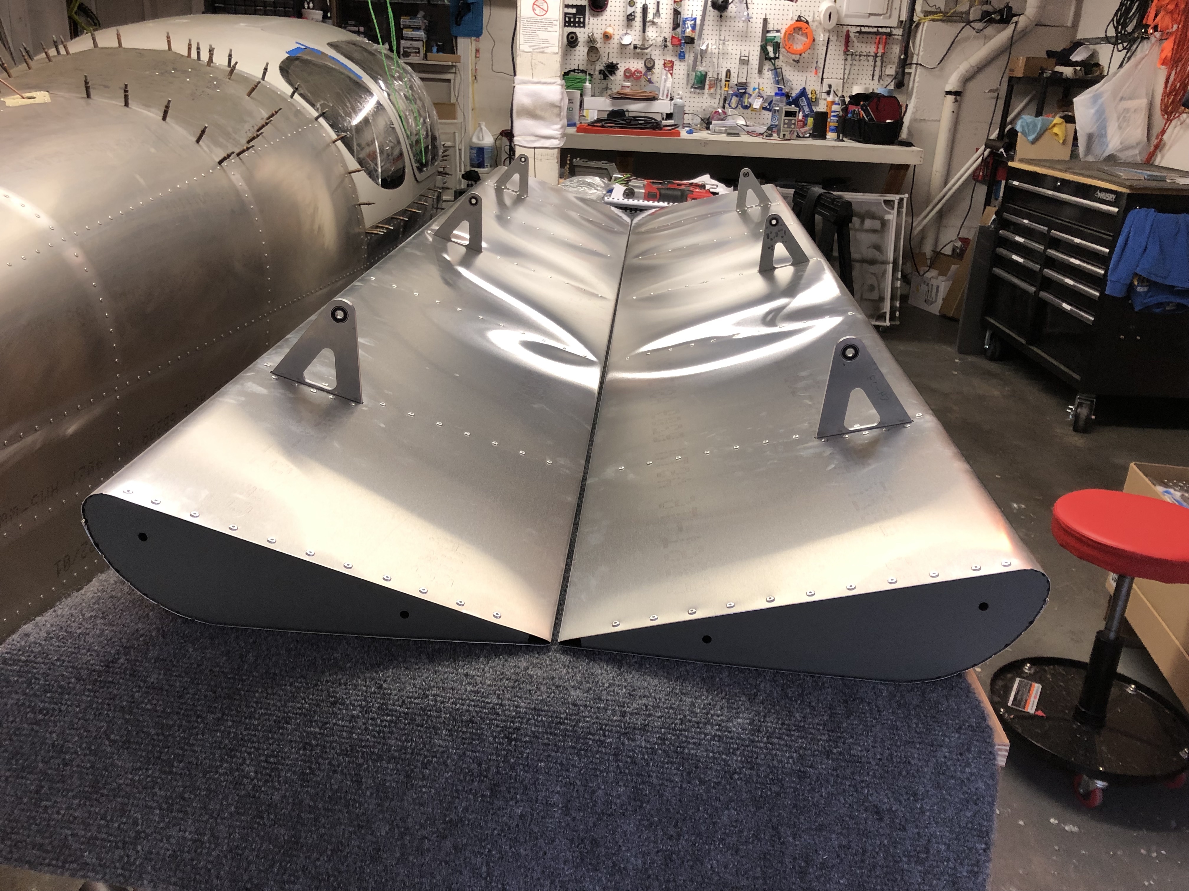
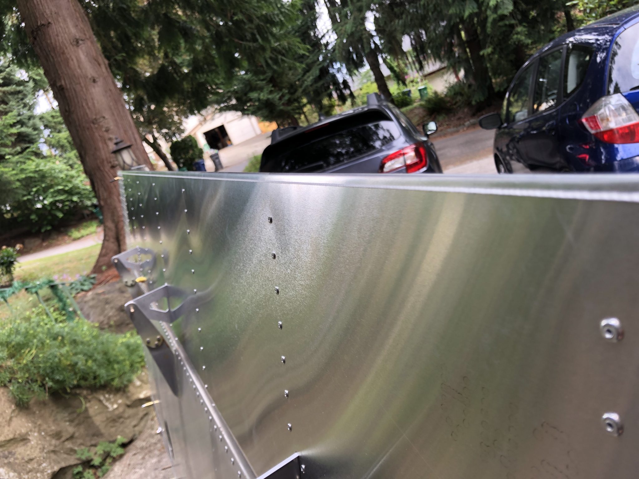
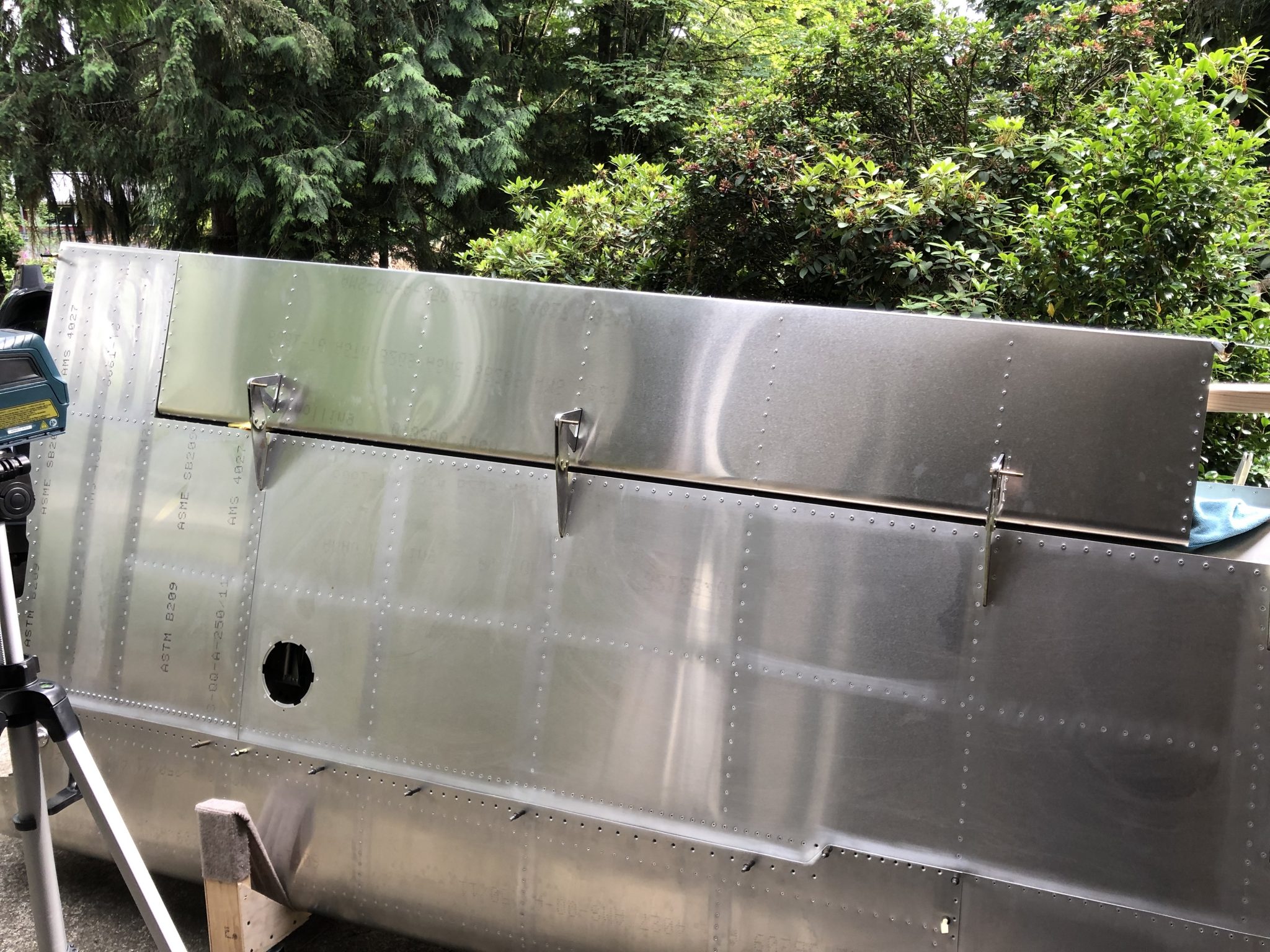
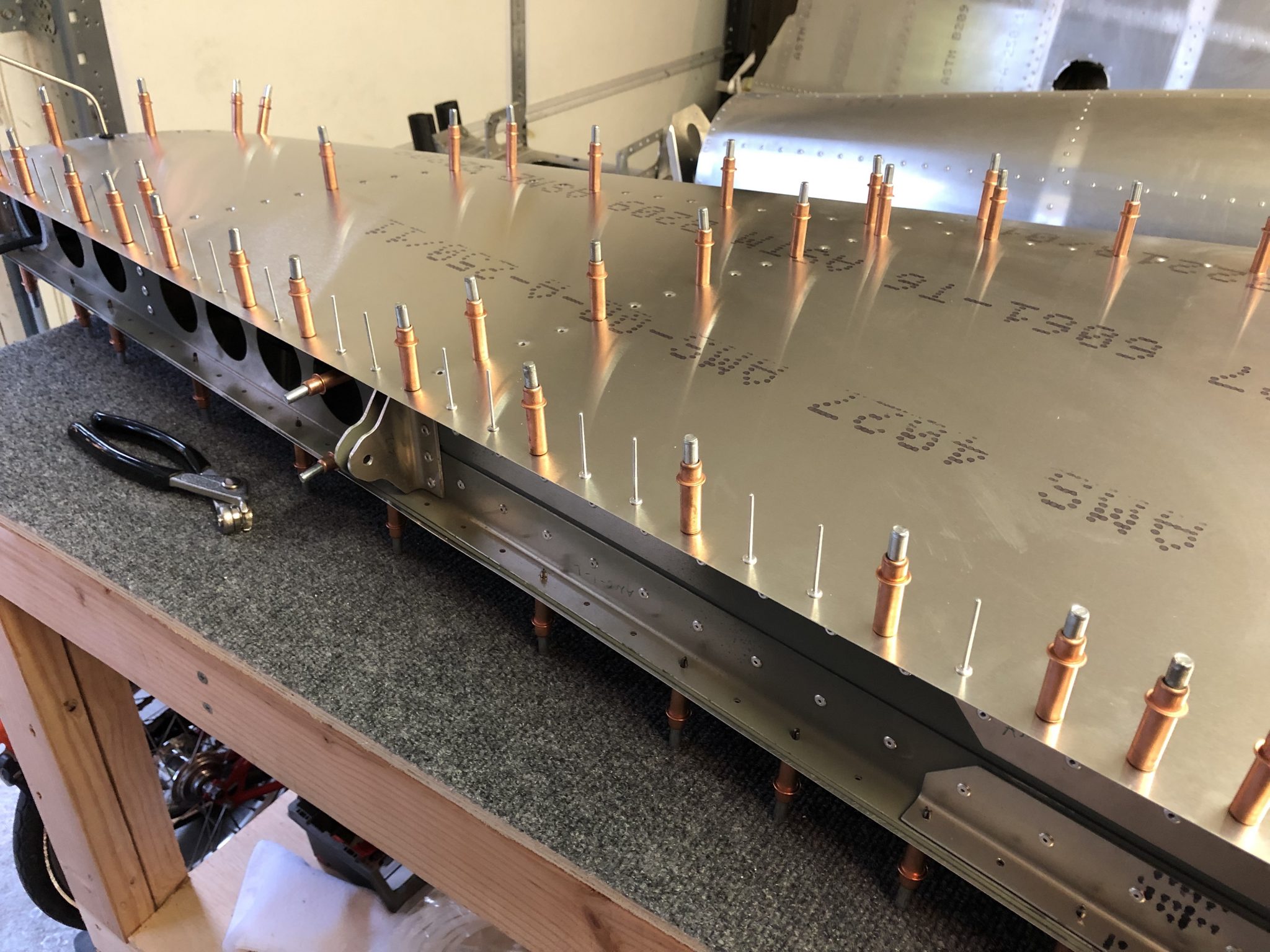
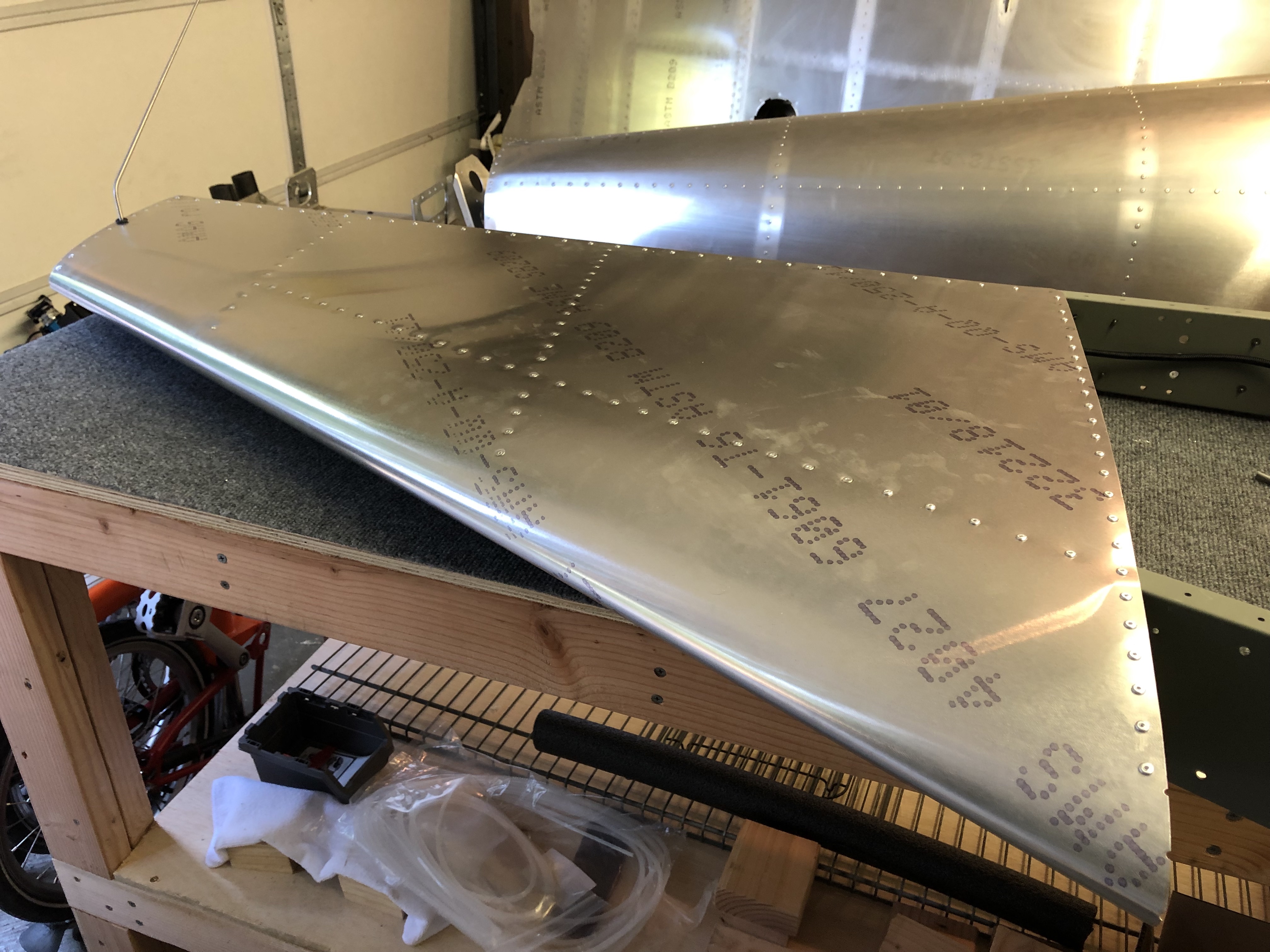
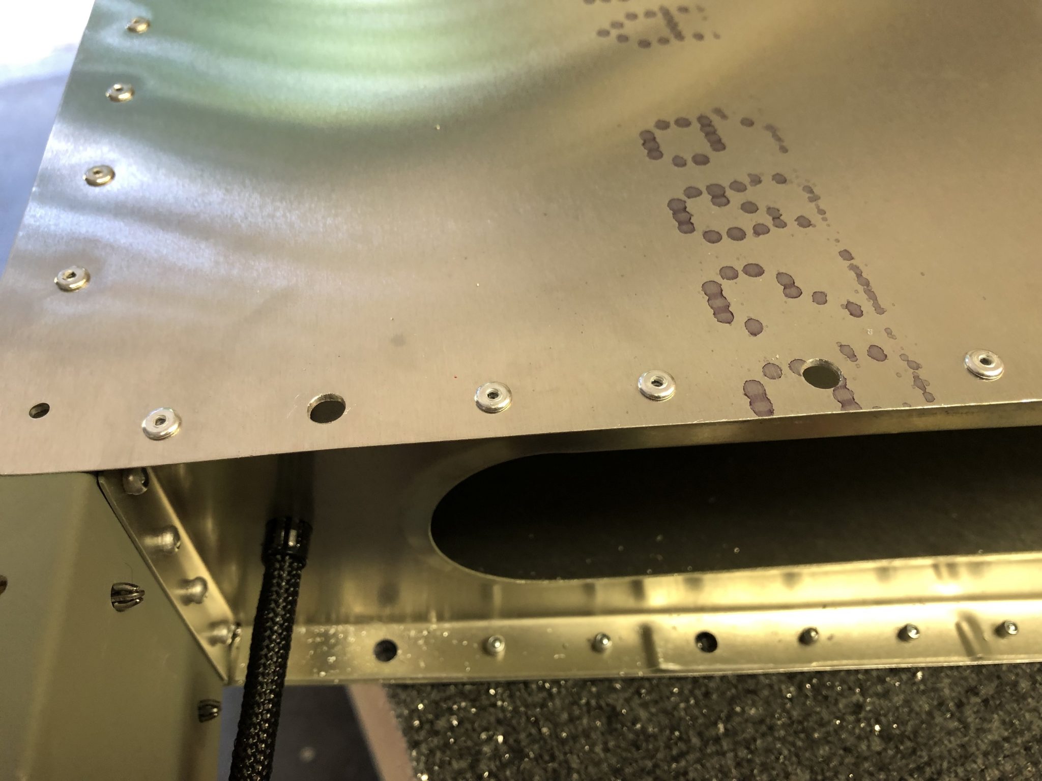
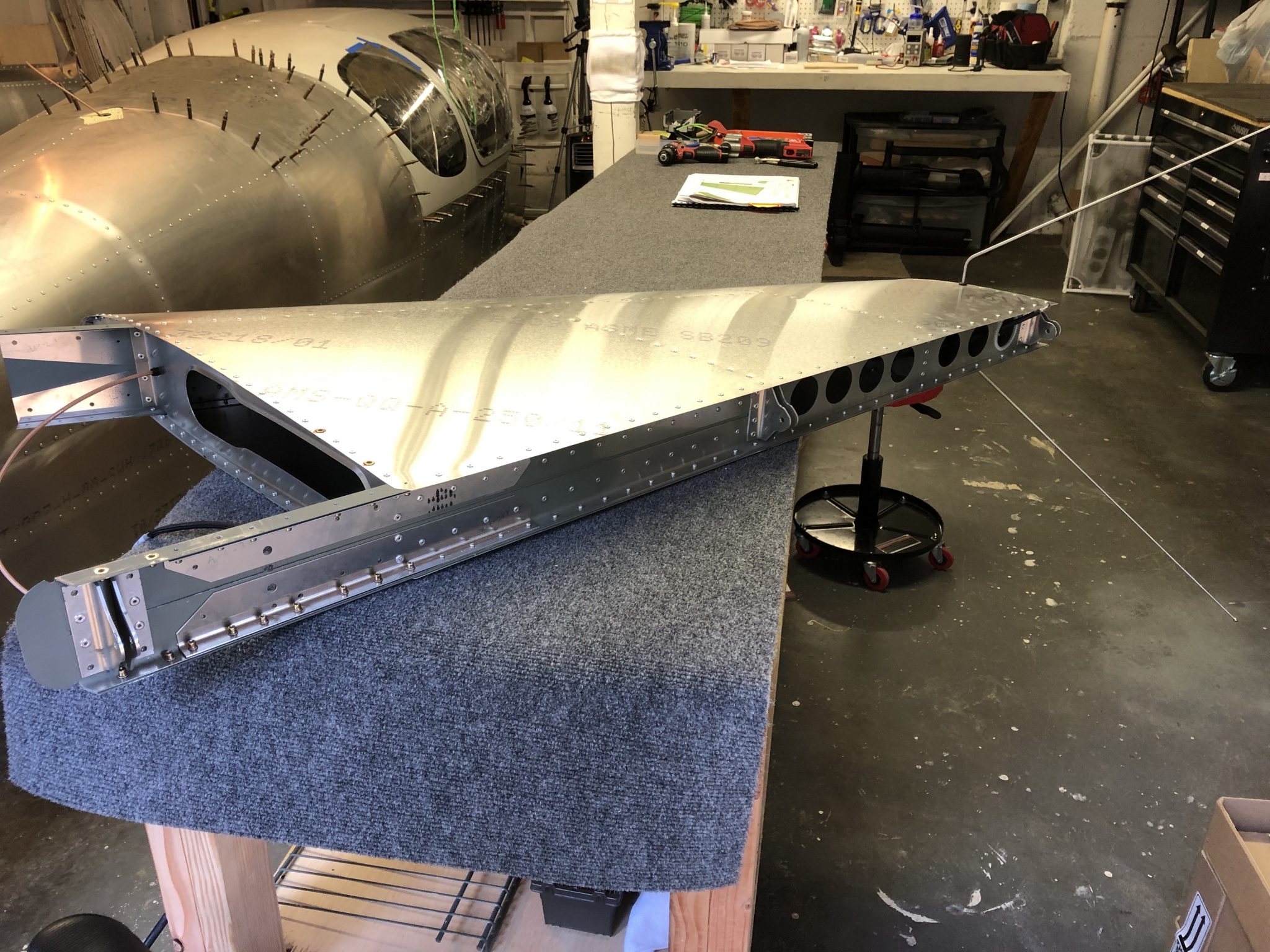
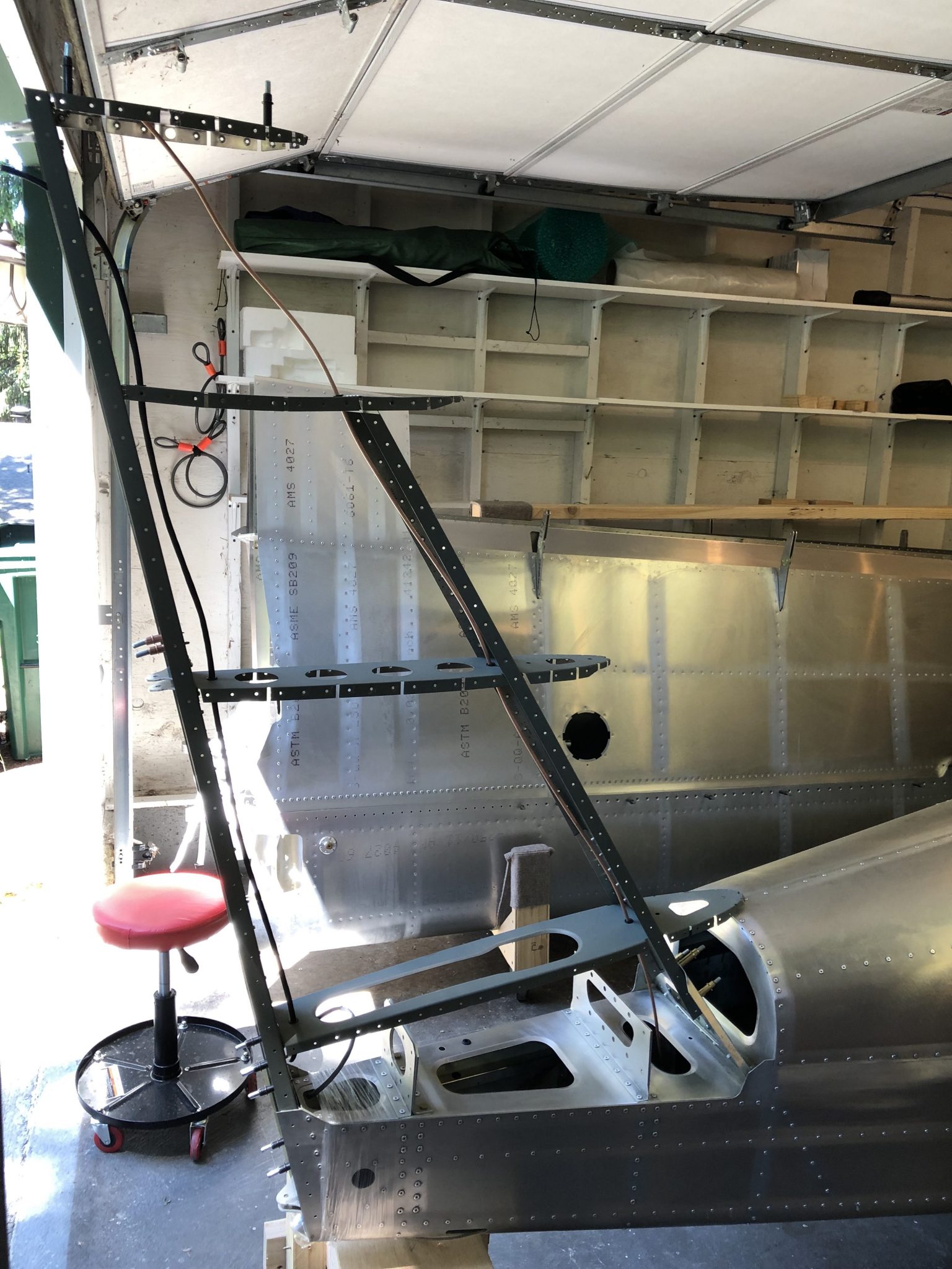
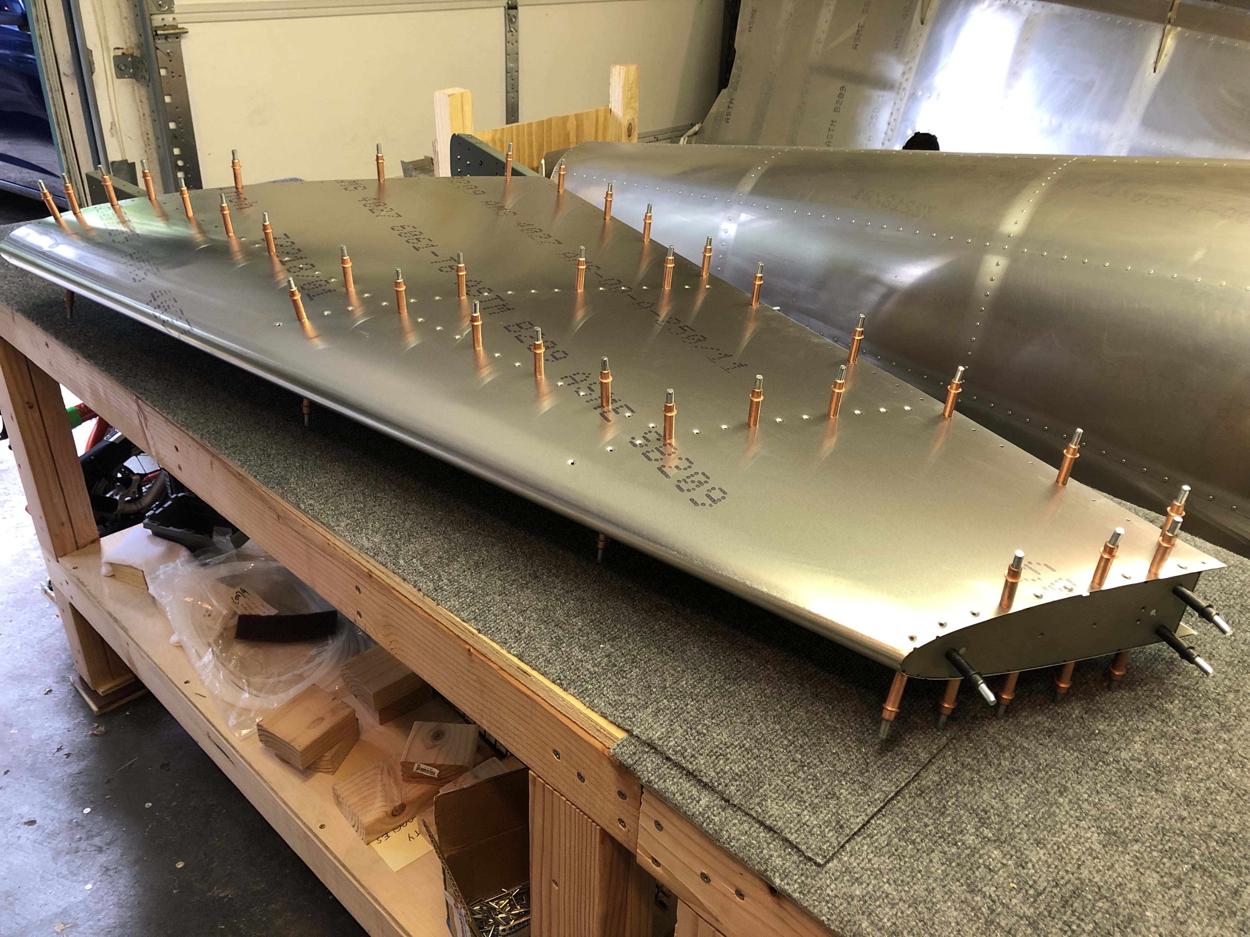
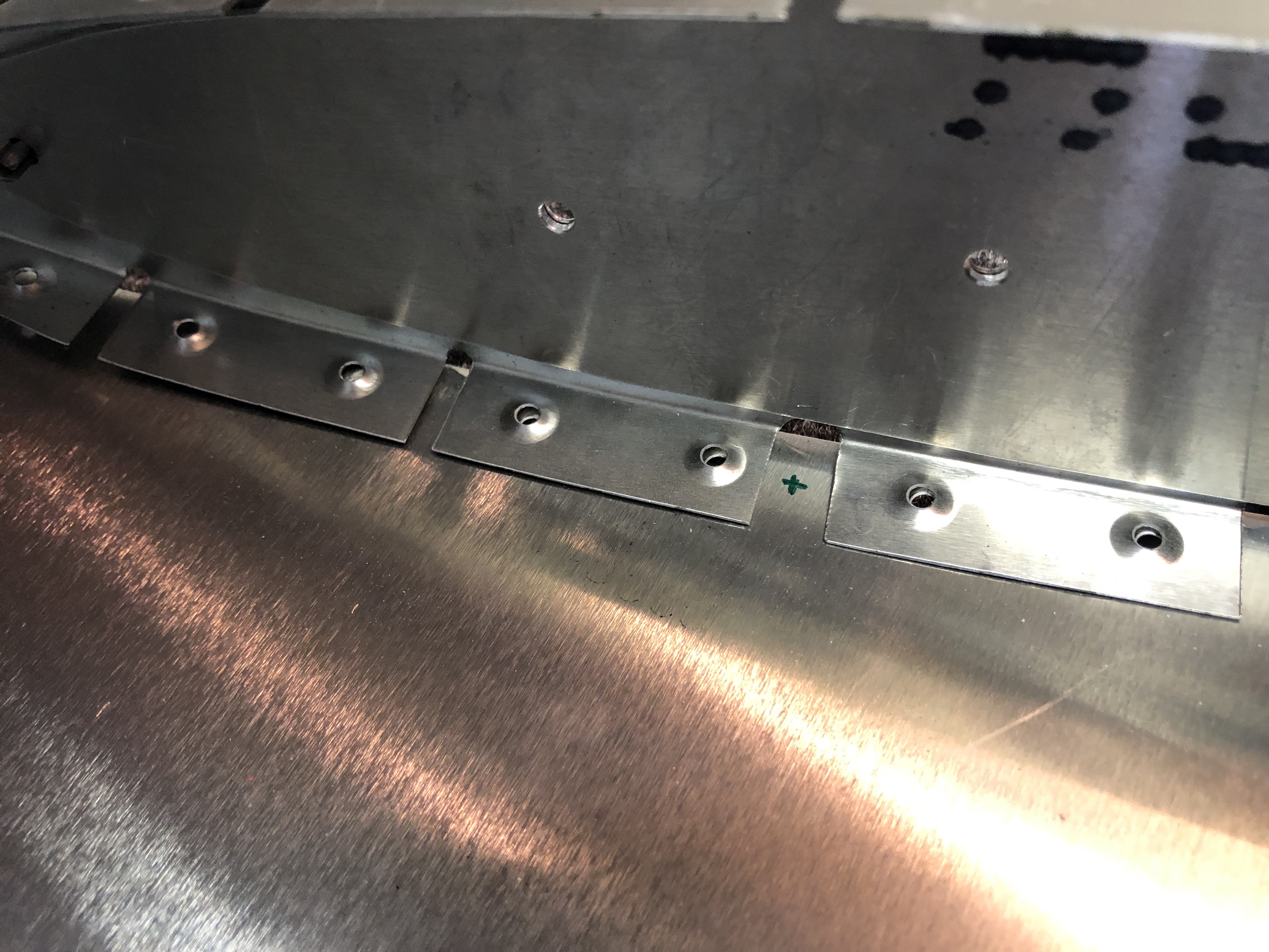
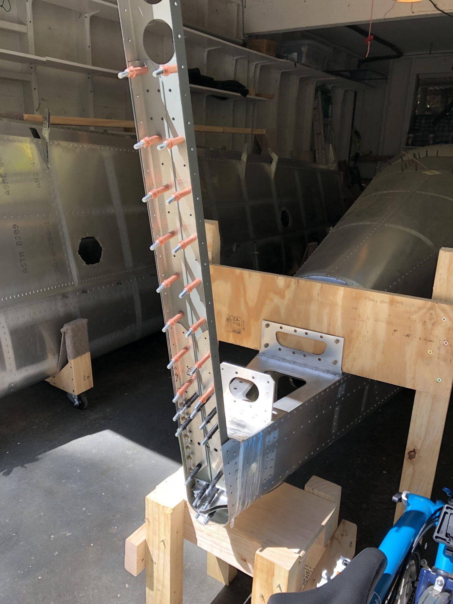
I then quickly measured out the length of the Antenna wire to install in the Vertical Stabilizer, cut it to size and ran it through the front holes. After I was done with that, I wanted to do a quick test fit of the Vertical Stabilizer Structure on the Fuselage to see where the holes would pass through.

Quick test fit to see where the wires come out Looks almost like an airplane

Antenna Coax wiring

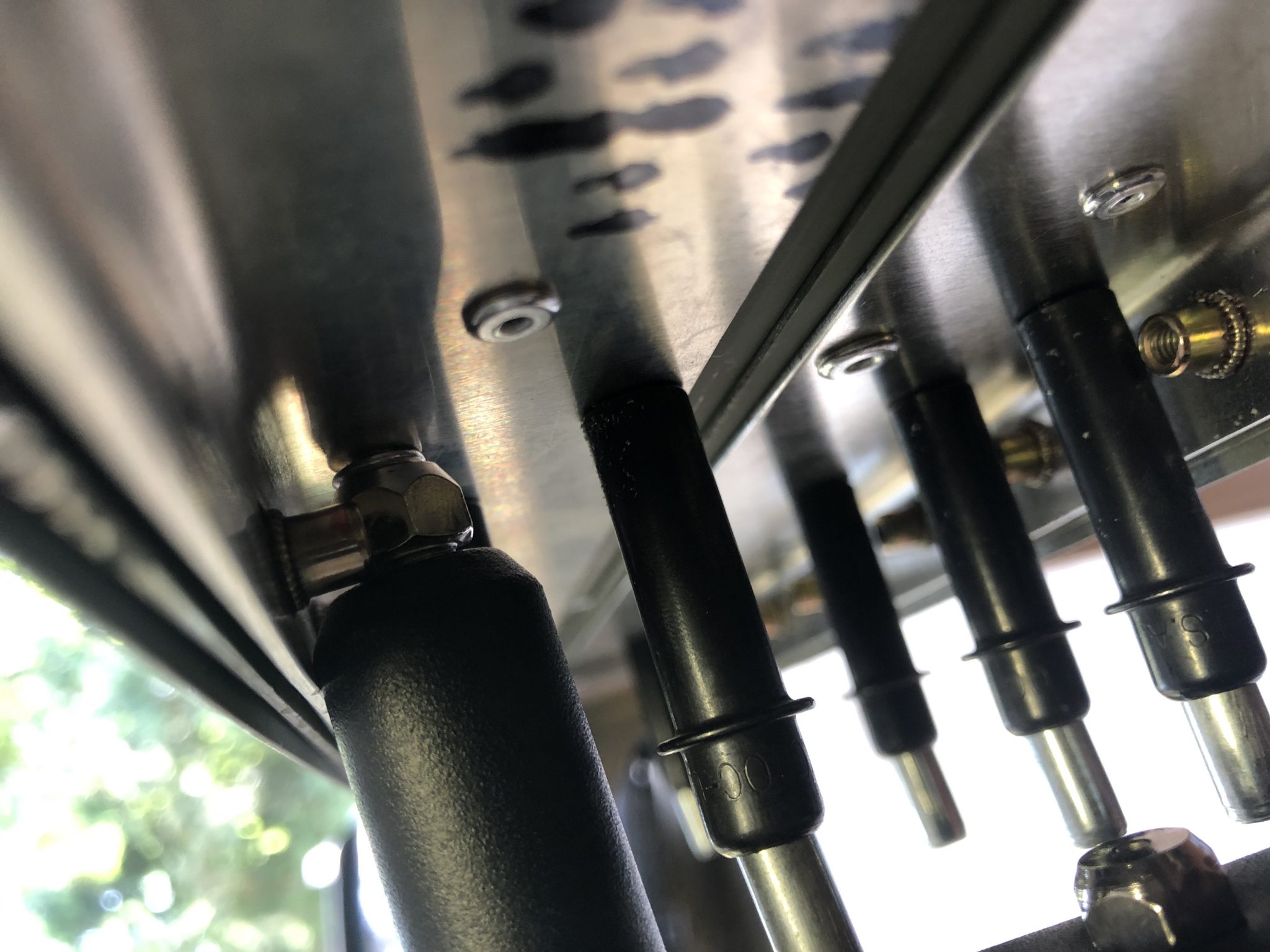
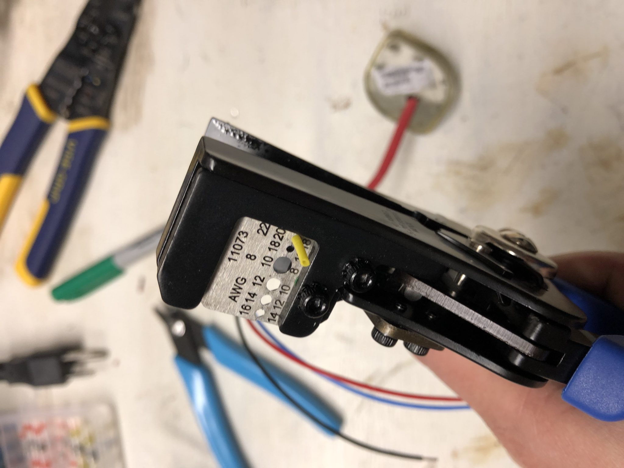
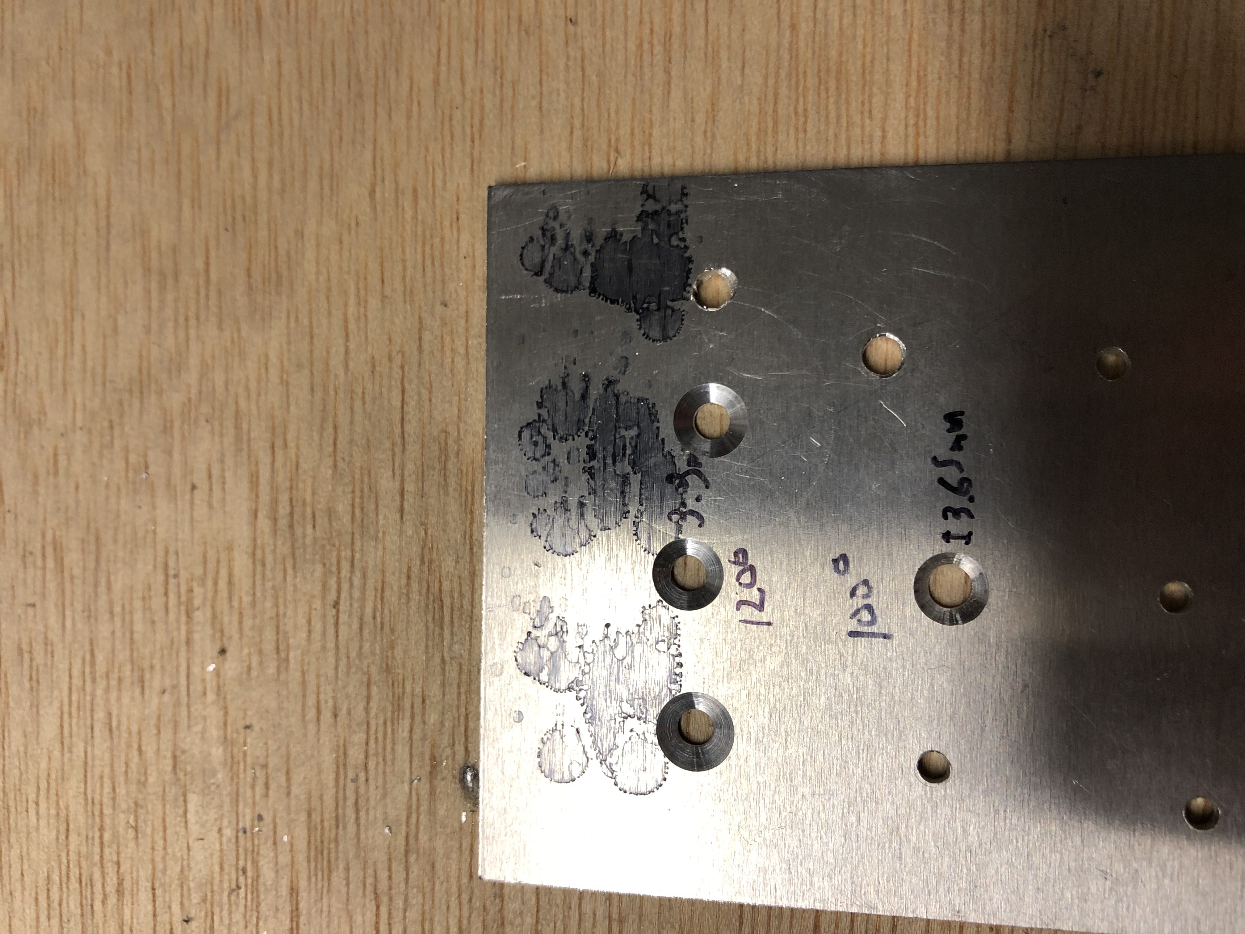
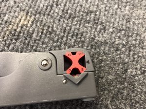
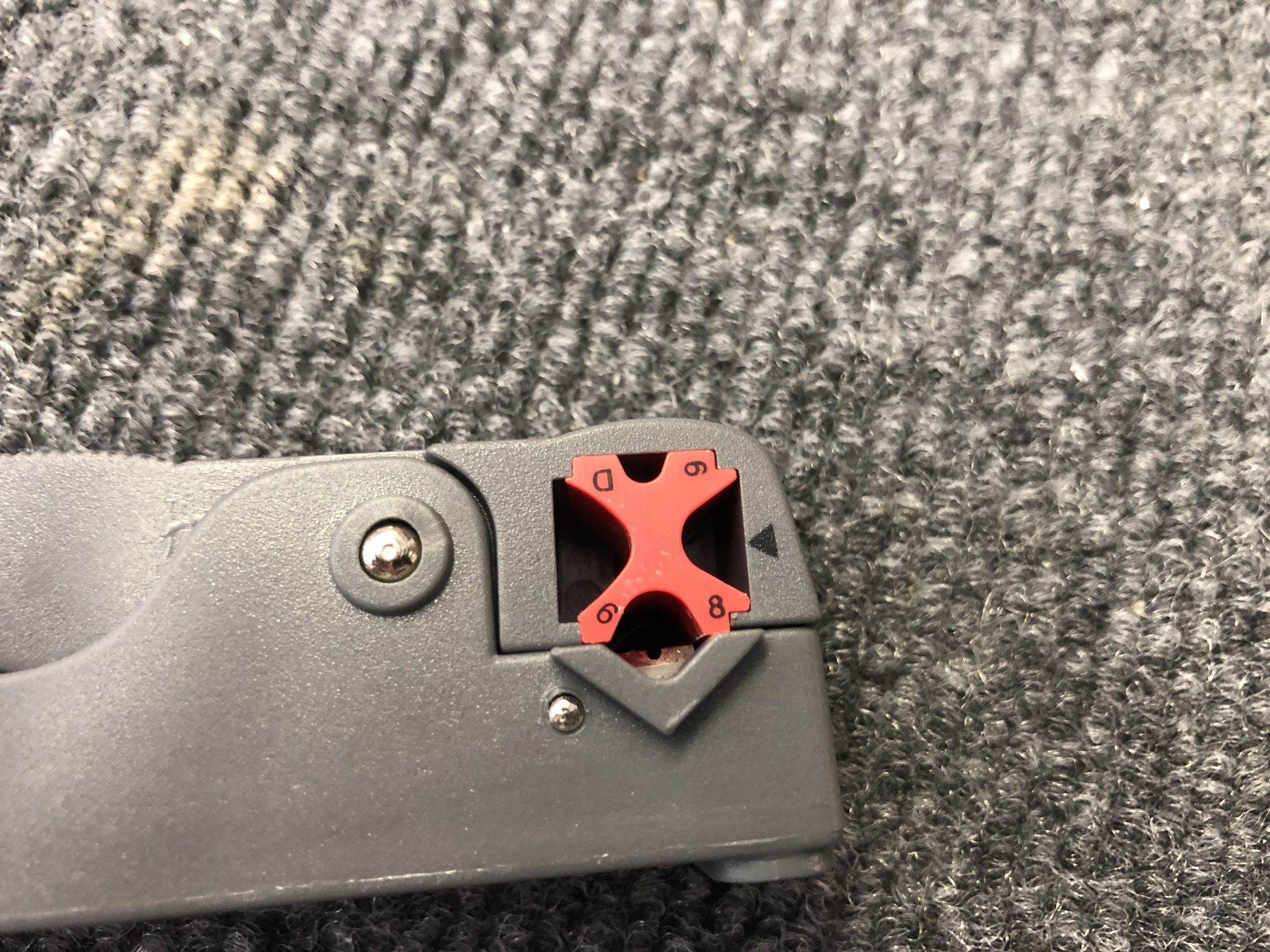
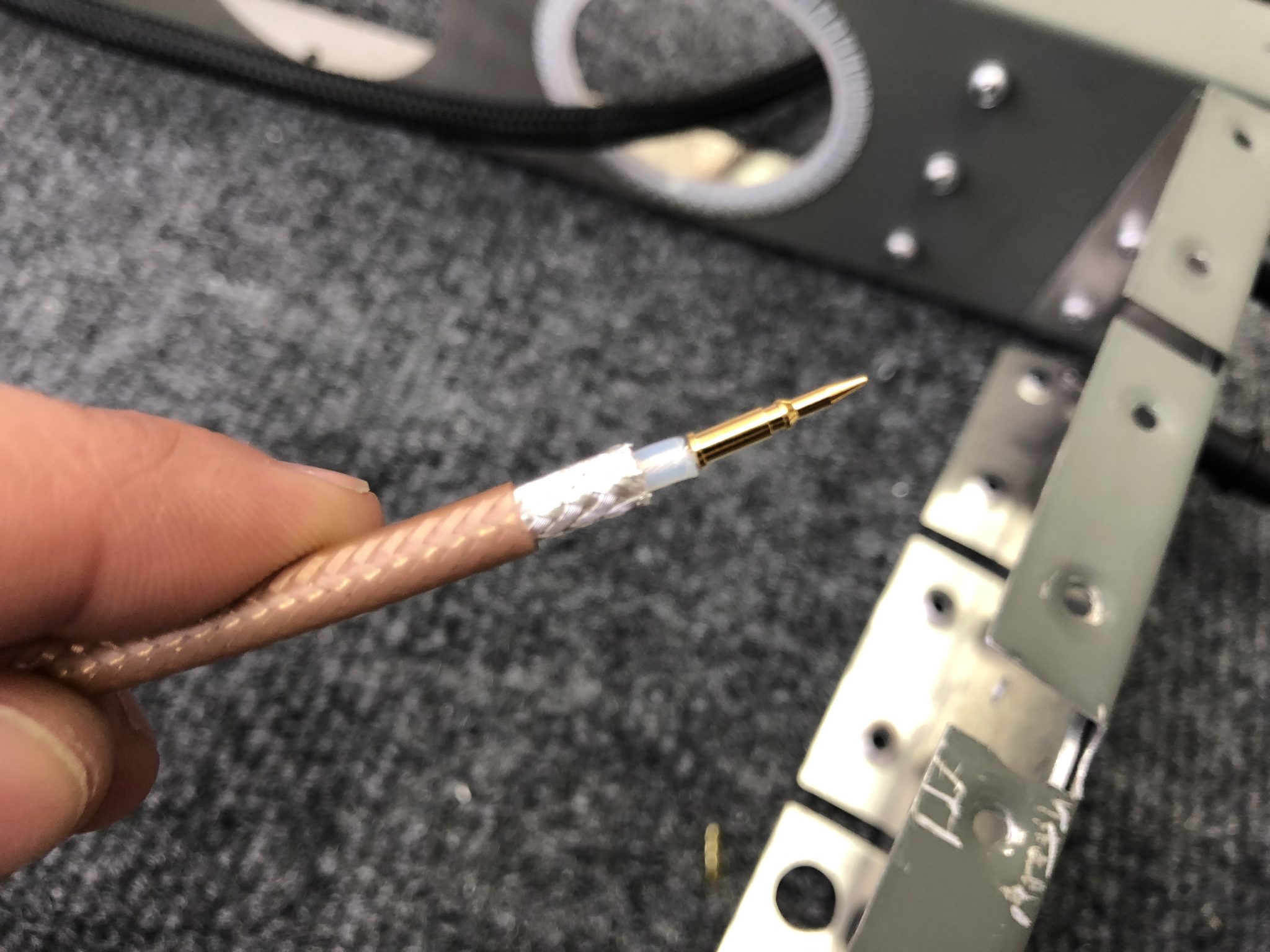
Once that was figured out, I moved on and did my first crimped coax connection. After a tip I saw on the homebuiltHELP channel, I bought this rotary coax stripper, which strips both the front, as well as the braided shielding in one go.
Rotary coax stripper

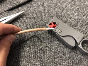
Before it was ready to use I had to do some adjustments for the lengths and depths for the cut, so I took it apart, while following the instructions and then moved the blade as needed. I’m using the SteinAir BNC Connectors, so I had to move the blade that exposes the outer shielding back by one position to the point marked E and the inner blade on mark B.
Blades set on mark E & B for the SteinAir BNC Connectors Correct location for RG400 stripping
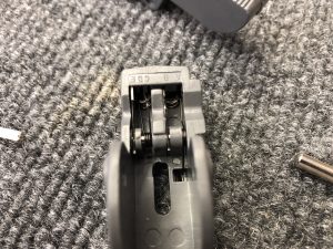
Then I adjusted the blade depth using the screws on the bottom and did a few test cuts to make sure the results are repeatable. I then put some light strength thread locker on the screws so they stay in position so I can now just use it without any further adjustments needed.

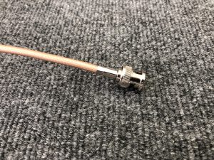
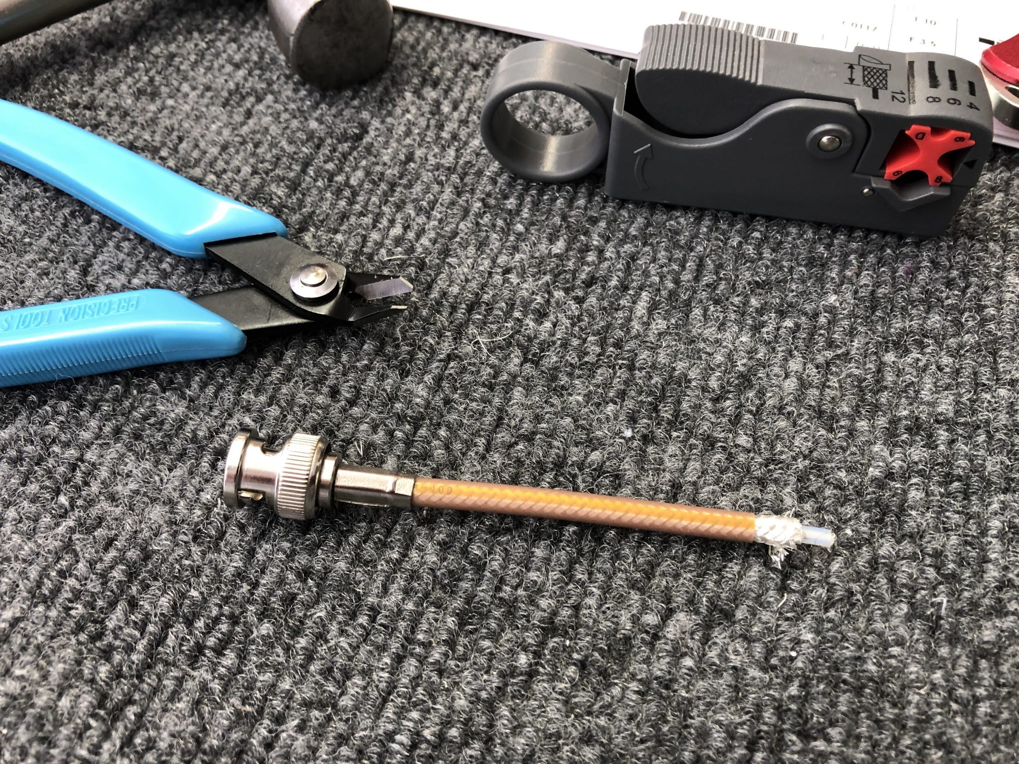
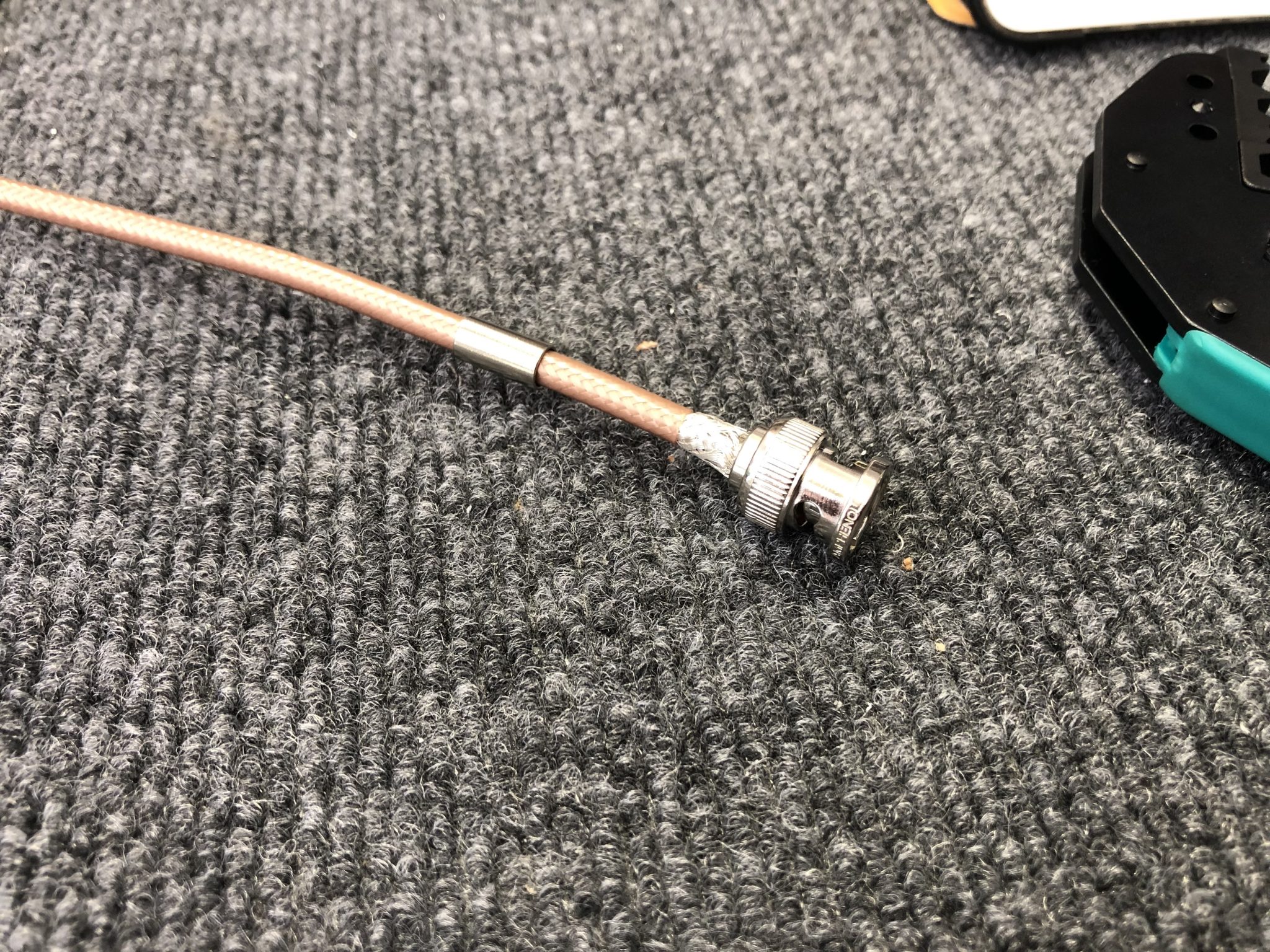
After that I did a quick test crimp of a connector to the small piece of wiring I used to calibrate the wire stripper, following the instructions from SteinAir.
Test crimp successful

Looked all good, so I repeated everything on the actual wire for the Vertical Stabilizer.Wire stripped and ready to install the center tip Connector attached and ready for the back shielding to be crimped Completed crimp of the connector Test fit of the connector on the Antenna

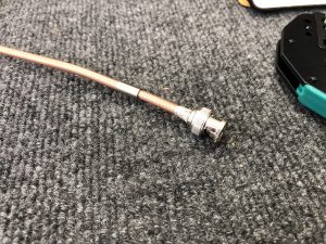
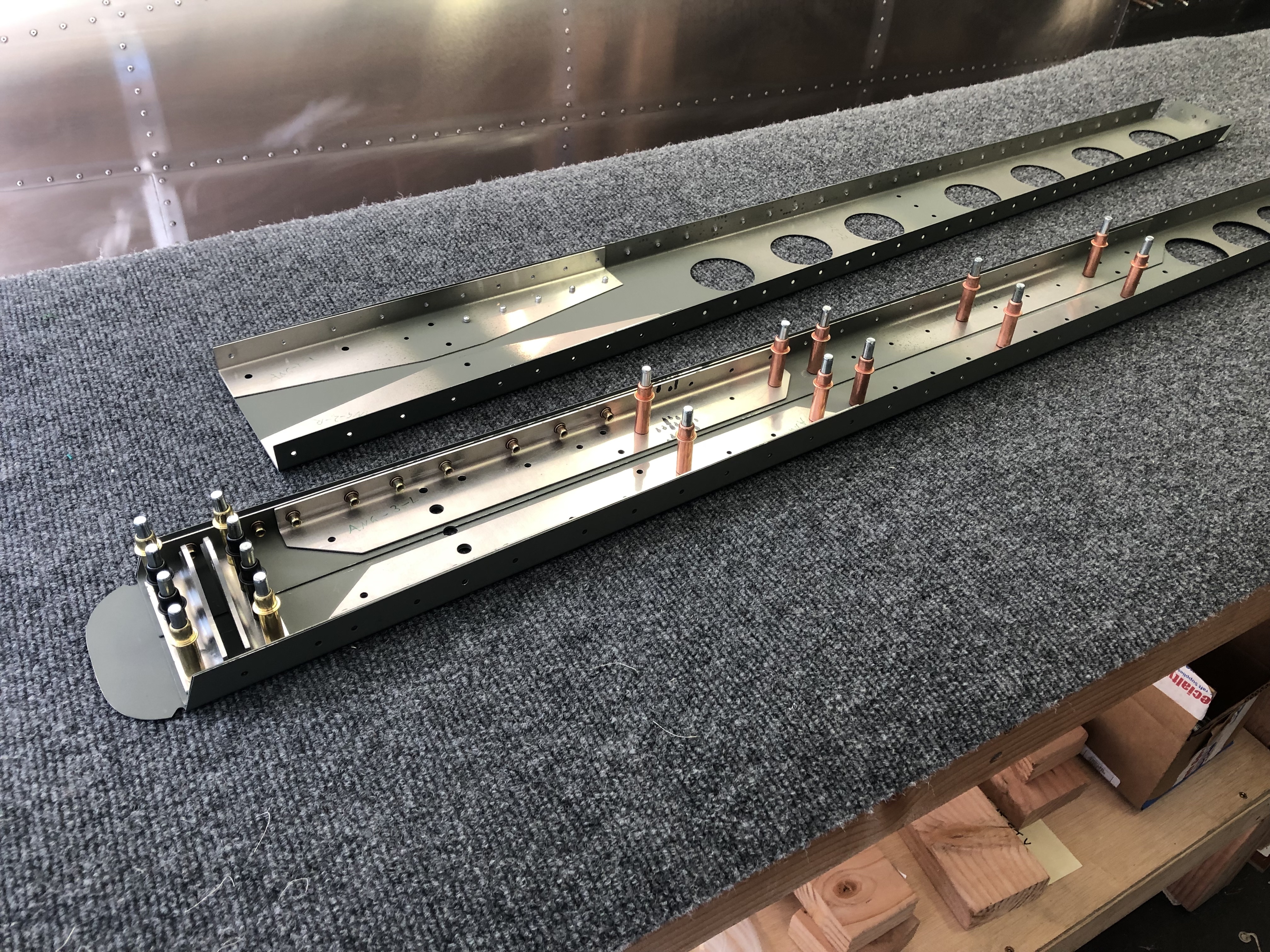
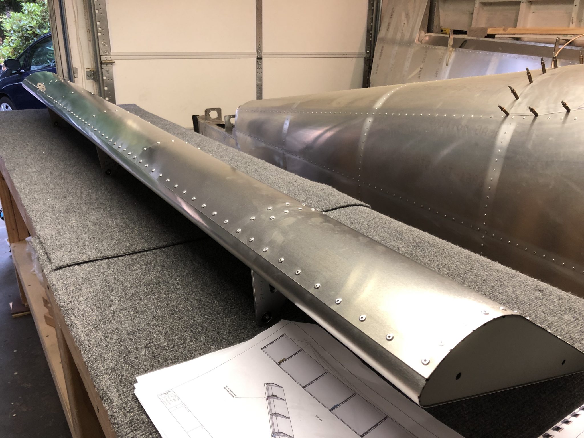
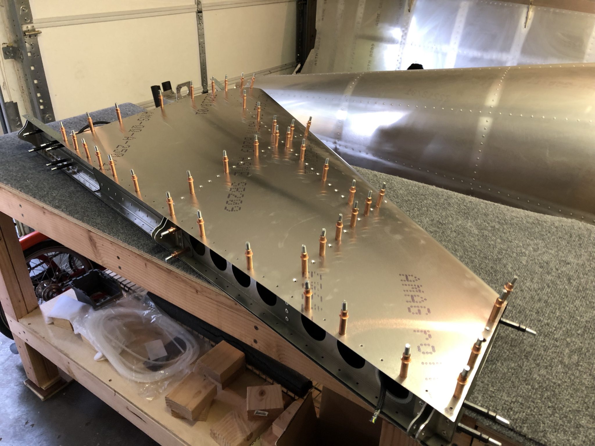
With all that done, I installed the wire in the Vertical Stabilizer and now I’m ready to install the Antenna and close up the skin.

Interesting side note on coax wiring and the use of a balun

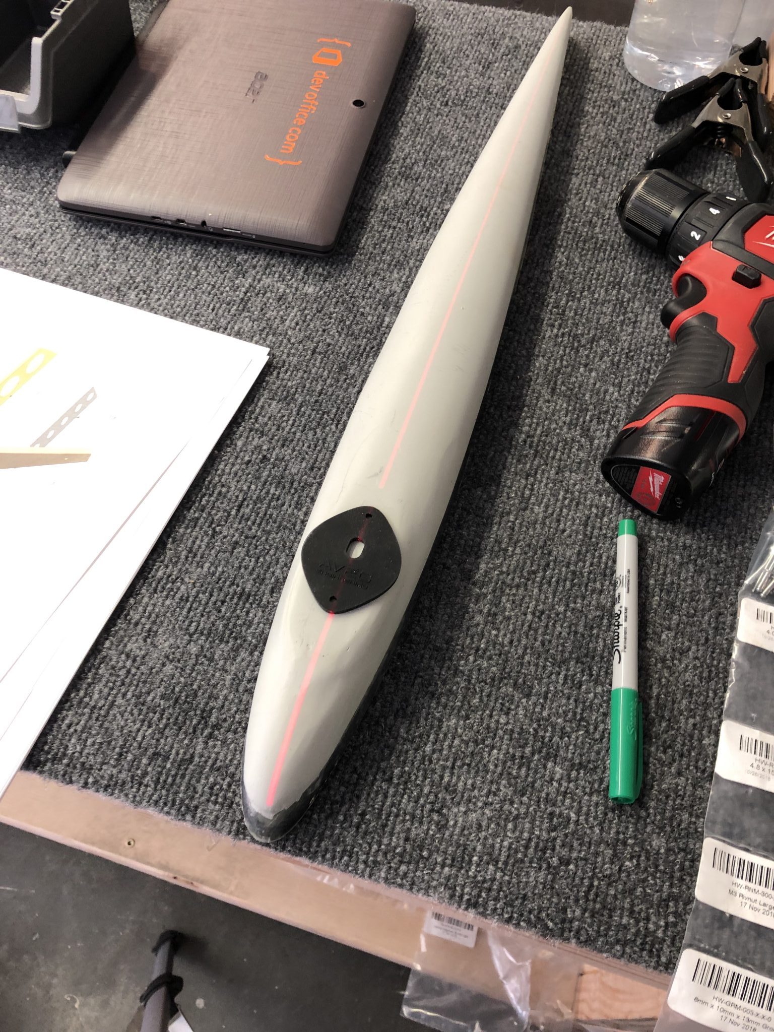
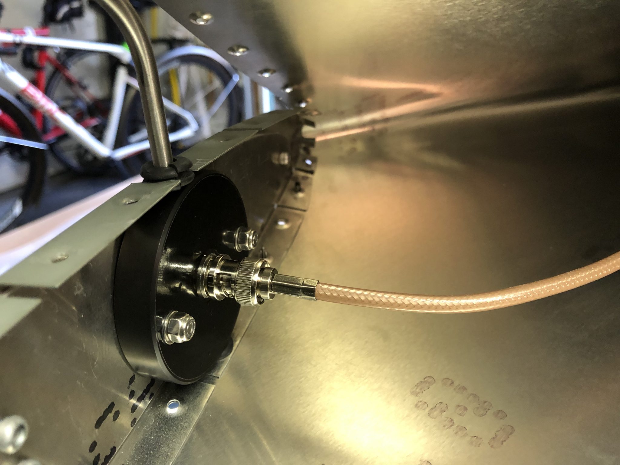
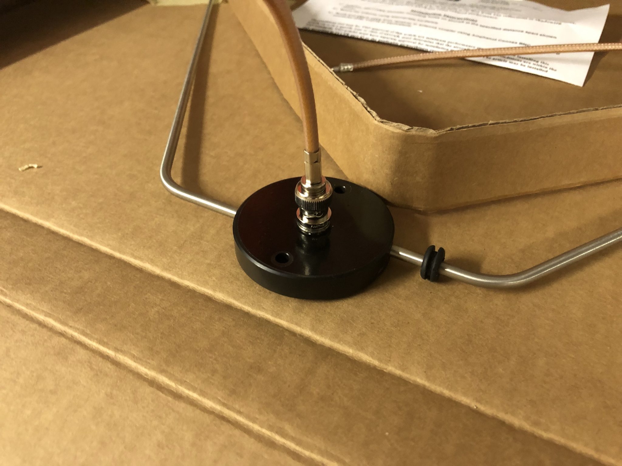
One other interesting thing I learned while doing this – I tested the wire I crimped for continuity to make sure there are no problems with the wire itself by checking (lack of) continuity between the shielding and the center core. This was all good, so my crimp is good.
After attaching the wire to the Antenna however, I figured I’d also check it with the wire attached to the Antenna and had a brief moment of confusion when I did get a positive continuity readying between the core and the outside. So I did some digging and found out that the use of a balun (in my case with the Rami AV-525, it is an internal balun) can create a DC short and thus will produce a continuous reading using a Voltmeter.

Vertical Stabilizer Navigation Antenna & skin fitting

Hours: 2.5

Before I can close up the Vertical Stabilizer skin, I need to fit the Navigation Antenna, run the wires for the Antenna and the rudder light and fit the skin including up-drilling the countersunk holes in the skin with the rib structure.

So one thing after another, first I gave a quick test fit for the skin and then drilled up all the countersunk holes.
Test fitting the skin and aligning everything to match up-drill the countersunk holes And found one hole that should be dimpled as well

After that was done, I went to work to fit the Rami AV-525 Navigation Antenna I’m going to use. I already fit the Antenna onto the inner rib a while ago before I built the rest of the structure, so now it was a matter of fitting it all with the skin to be able to close the skin around the Antenna.

On the left side, the Antenna comes out one of the pre-drilled rivet holes, so I just had to up-drill that to the correct size.
Enlarged hole for the Antenna on the left side

For the right size, the Antenna comes out offset a bit further behind, so I marked out where I needed to make the hole in the skin, then used a center punch to get a good center to drill the hole:
Marking where the notch for the Antenna has to go Centerpunched the spot for the hole to goHole drilled on the right side for the Antenna

With the hole in place, I cut back a small notch, so that the skin can slot around the Antenna since the arms of the Antenna are fixed to the internal balun.Notch to slot the skin around the Antenna

After all that was done, I put it all together for a final test fit:Left side view of the Antenna in place on the Vertical Stabilizer Right side view of the Antenna in place on the Vertical Stabilizer

Looks all good, so now I need to finish running the wires on the inside and then I can rivet the skin closed.


Vertical Stabilizer Structure

Hours: 3

After finishing attaching the rivnuts to the rear spar parts the other day, I put everything together and did a brief test fit with the Fuselage where it attaches into. Vertical Stabilizer rear spar in place with the Fuselage

After putting together the rear spar, I also enlarged the holes in the spar so that the M4 screws can actually be screwed in and enlarged the bottom two holes so that the bottom rivnuts sit flush with the spar.
 Holes enlarged for the M4 screws and bottom two holes enlarged for flush fit of those 2 rivnuts,Screw holes enlarged and the bottom 2 rivnuts made flush with the spar

Looked all good, so onto riveting together the inner structure of the Vertical Stabilizer.Riveting the rear spar of the Vertical Stabilizer Adding the inner ribs to the rear spar Structure coming along Inner structure of the Vertical Stabilizer riveted together

I also enlarged the holes for the wiring and added snap bushings since the inside won’t be accessible once it’s closed up and the snap bushings have a better durability than rubber grommets.
Snap bushings for the wiring

There was one spot on the rear spar where one rivet was very close to one of the rivnuts and I had to use my manual hand rivet gun to pull the rivet as the head of the Milwaukee was too large to get in there.
Clearance between the rivnut and the rivet was very tight so I had to use my hand riveter instead

Completed inner structure of the Vertical Stabilizer:Completed structure of the Vertical Stabilizer


Lots of Rivnuts on the Vertical Stabilizer

Hours: 1.5

After putting the Elevator construction on pause due to the alignment issue of the center rib. I decided to get started on putting together the Vertical Stabilizer. I’ve heard back from the Factory and it turns out that they’ve changed the Rib and will be sending me the correct new versions of the ribs (EL-RIB-001-C-E-1 & EL-RIB-101-C-E-1), so I’ll have to wait until I get those.

So onto the Vertical Stabilizer – the bottom of the rear spar holds a lot of M4 Rivnuts, so it was time to updrill the holes to the correct size in order to fit the rivnuts.Getting my tools ready to install the rivnuts

Using the step-drill bit I enlarged the holes just a bit smaller than the Rivnuts and then finalized it to the exact size using a hand reamer since you don’t want the hole to be any larger than the not so it gets a tight fit.
Hand reamer marked to the correct size using masking tape Test fitting Rivnuts after reaming them to the correct size

Once I was done enlarging all the holes I took care of deburring the holes and then went to work installing all the rivnuts using the Astro ADN14 Rivnut puller attachment for my drill and adding Loctite 277 (red) Threadlocker for added strength.Before deburring the holes after I enlarged them Tools ready to install the rivnuts Rivnuts installed using my bench vise to hold the bracket in place Done installing all the rivnuts

After all that was done, I put together the spar with the brackets for a quick test fit. While doing so I also found an error in the instructions, which say to rivet the hinges on the bottom with 8 (4 a side) 4mm rivets, but actually, only the center one (where I have black clecos) should be riveted, the outer ones will be bolted to the Fuselage (which is why they have larger holes already and I temporarily used the larger golden clecos to hold it in place), so I sent the Factory a note to correct the instructions.
Vertical Stabilizer Rear spar with brackets clecoed in place

Rudder Anti-collision light wiring

Hours: 2

Now that the Rudder is almost complete, I needed to make the wiring for the Anti-collision light permanent. The existing wire of the Aveo Posistrobe Minimax I’m using has 4 wires (ground, power, strobe, sync), so I needed to splice those onto the wire so I could run it through the structure.

Since this is a permanent connection, I’m using Heat Shrink Solder Sleeves, which have solder in the center and when you heat it up, the solder melts and the sleeve shrinks down to create a good seal.

After that was done, I added some expandable braided Sleeving over the wire for extra protection.
Expandable Braided Sleeving for the wire

I up sized the hole for the wire to pass through the fiberglass tip using my step drill bits and then ran the wires through the structure and out the front hole, which I also had to drill up as per the instructions. After some more research, I replaced the rubber grommets with snap bushings. They last longer and for the front hole in particular, they hold on better since they snap in place.
Finalized hole size for the wiring to pass through the fiberglass tip Snap bushing for the wire to come out of instead of using rubber grommets

Here’s the light mounted and completed wiring done.Light mounted and wiring finished

Now the last thing to do is close up the top. Inspired by a discussion from a while ago on the Sling Builders group, I was contemplating the idea of making the fiberglass tip removable using nut plates and screws, but I think I’ll end up just riveting it closed.


Rudder Tip fitting & riveting the skin

Hours: 2.5

After having primed the inner surface of the Rudder skin the other day, I had all the pieces together to start working on finishing the rudder.

I attached the skin onto the structure and clecoed it into place.Rudder skin clecoed in place

Fitting the fiberglass tip

Once that was done, I went to work to fit the fiberglass tip onto the skin. I had to trim a little bit away from the bottom of the fiberglass. I made a first rough measurement, trimmed it away using my Dremel and then tried to fit it in.
First trim mark on the fiberglass tip

After aligning it all, I did a second small pass to trim a tiny bit more, placed it into the skin again and then it looked all good.
Tip fit in place and held in place using some clamps

Since the instructions are very explicit to make sure that the alignment of the rudder is perfect, I checked the alignment from all sides and it all looked good.
Rudder checked for alignment using laser level Rear of the rudder checked for alignment using laser level

After all that looked good and triple and quadrupple checking that the fiberglass tip sat flush in the skin I made marks for match drilling the holes and then went to work and carefully drilled the holes into the fiberglass.
First few holed drilled into the fiberglass tip Finished drilling all the holes in the fiberglass tip

Countersinking the front of the fiberglass tip

Once that was done, it was time to countersink the holes in the front. The instructions contradict themselves – only the first 7 holes get countersunk rivets, which mathematically adds up properly to the 32 rivets (2 x 7 on the top and 2 x 9 on the bottom = 32). So after counting all the holes and re-checking the instructions and doing basic math, I decided to only countersink the first 7 holes. I sent an email to the factory yesterday and they confirmed that I was right and they’ll fix the instructions in the next iteration.
Instruction error about countersinking

Before I went to work with the countersinking, I calibrated the micro stop countersinking tool using a scap piece of Aluminum to ensure the depth was set correctly and made sure that I had the correct 120 degree pilot cutter in the tool (I made a whole post about why using the 120 degree pilot was important here).
Calibrating the Microstop Countersinking tool Making a test countersink on a scrap piece of metal

After all that was ready, I went to work, mounted the fiberglass tip gently in my bench vise and started drilling the countersink holes.
First countersunk hole drilled Checking depth using a countersunk rivetAll the countersunk holes drilled in the fiberglass tip

All the countersunk holes came out well and everything sits flush now.
Flush fit of the fiberglass tip in the Rudder

Riveting the skin

So after all that I went to work and started riveting some of the skin.Time to rivet the Rudder skin The close quarter wedge came in handy for riveting in this tight spaceRiveted part of the Rudder skin

Rudder skin fitting & Anti-Collision light mount

Hours: 3

Over the past few days I spent some time organizing the next few parts of the Empennage such as organizing the Vertical Stabilizer parts and what I needed to finish for the Rudder.

Fitting the Anti-collision light

I got the Aveo Posistrobe MiniMax anti-collision light to mount onto the rudder tip and started working on fitting it on.
Aligning the strobe light seal to find out where the holes should go Marking center linePilot holes drilled Double checking the holes aligned properly and then enlarging the hole for the wires to pass through
Light temporarily on top and shining bright like a diamond.
Quick test with light on

Mounting plate

The first iteration of the Empennage assembly instructions called out for a mounting plate to go inside the fiberglass tip to add structural reinforcement for the rivnuts, but the latest version of the instructions is missing it, so I sent a question to the factory why.

In the meantime, since I assume that it’s still a good idea since both the Sling 4 instructions as well as the first version of the instruction call for it, I decided to fabricate my own.

I started tracing out the rough dimensions of the area and then measured it down to how it would fit. Then I made a first version out of cardboard to see if the dimensions I estimated would work.
Rough outside dimensions of the strobe light traced Test fit of cardboard cutout

Looked good, so then I copied my cutout onto the sheet metal and went to work cutting it out. I used a OLFA Scoring knive to score the cut, based on a tip from HomebuiltHELP. Since my metal was pretty thick I only scored it with that and then used metal snips to cut it, but for thinner metal you can actually make the whole cut using the scoring knive to make great straight cuts.Transferred cutout onto aluminum sheet Metal piece cut and ready to drill the holes

After that, I deburred all the edges and the holes and then checked the final fit in the rudder tip.Plate fits great in the tip Clecoed in place

Fitting the skin

I also test fitted the skin onto the rudder and checked how the tip will fit in. The skin came on fairly easily, but I will have to trim a little bit of the fiberglass tip so it will fit in.
Skin fitted and fiberglass tip put in place Need to trim off a bit of the rear of the fiberglass tip

I still had to prime the inside of the skin, so now that I know it all fits together fine, I will rivet the skin on and then work on the final trimming for the rudder tip so it fits in and then I will need to match drill the holes into the fiberglass tip and countersink the front holes.